COOPERATIVE COMMUNICATION AND COOPERATION
TECHNIQUES IN SENSOR NETWORKS
1BENSLIMANE MOHAMED, 2ABDELALI IBRIZ, 3HARTI MOSTAFA
1PhD Student., Transmission and Treatment of Information Laboratory, FST FEZ , USMBA 2PH ., Transmission and Treatment of Information Laboratory, FST FEZ , USMBA 3
PHE ., Transmission and Treatment of Information Laboratory, FST FEZ , USMBA
E-mail:
1[email protected] , 2[email protected] , 3[email protected]ABSTRACT
The wireless sensor networks have been around for a decade beneficing the progress of miniaturization of electronic and control of wireless communications that helped decrease significantly the production costs. We begin with a brief overview of sensor networks and their applications. We go through the following presentation of the cooperative communication and technical cooperation. The following sections are devoted to the introduction of technical MRC (Maximal Ratio Combining) used a combination of signals received from the same package.
Keywords:Network Sensors, ZigBee ZigBeef, Body Area Wireless Network (WBAN), Maximal Ratio combining (MRC), Media Access Control (MAC), Cooperation.
1. INTRODUCTION
In the last decades, the progress has been made in the fields of microelectronics, micromechanics and wireless communication technologies have produced a reasonable cost component of a few cubic millimeters in volume. Therefore, genuine micro sensors are embedded systems.
Nowadays, we have witnessed an incredible evolution of wireless sensor networks in various fields: such as military, environment monitoring and medicine.
Despite the remarkable progress in this field, there are still many problems to solve. Malthus, new protocols have Been Proposed to deal with the medium access control, routing, etc... In sensor networks.
However, some key issues: such as synchronization in the acquisition and data access are still in development research axis.
Indeed, the study of year based sensor networks in medicine and in cardiology
Particularly Will lead us to identify new needs in synchronization and data sharing for All which we need to find in the form of architecture, protocols and algorithms [2] solutions application. In our research we will rely on wireless sensors to remotely monitor cardiac patients. [3]
In this paper we will identify the needs in architecture, protocols, algorithms and tools for developing a solution to monitor the status of cardiac patients at home.
2. SENSOR NETWORKS
2.1. Introduction
other components. The radio provides wireless communication with other sensors. The pickup unit retrieves measurements from environmental measurements and battery supplies all the components of the sensor.
Figure 1 - Architecture of a sensor
With miniaturization, sensors invaded all fields of applications.
In the field of environmental protection, sensors are used to track animals such as zebras, [5] ecosystems such as the Columbia [6] or the activity of volcanoes [7] River. In health, sensor networks provide remote monitoring of patients [8] and prevent emergencies in case of critical condition. [9] They also allowed the replacement of the natural retina by an artificial retina [10]. In the industrial field, the sensors ensure the safety of people and facilities. [11]
Many other applications [7, 12] have been implemented and tested. However, despite their impressive success, research must continue to go beyond the existing proposals in terms of throughput, applications, number of nodes and interoperability. Indeed, the limitations of the physical capabilities of the sensors generate several problems related to energy consumption and management of wireless and radio communication channels. We present the following three detailed examples of applications of sensor networks and some of the challenges
faced by researchers in the coming years sections.
2.2. Applications
The sensors operate in several areas to facilitate the daily lives of men. We present in this section three examples of applications of agriculture, health and energy.
Agricultural Application: In the United States, the cattle have large herds whose manual supervision requires great efforts.
The ZigBeef implementation [13] is to facilitate this task. Cattle are identified and equipped (in the ear) with multiple sensors Zigbeef information. With this application the farmer has two types of services:
- The identification of cattle that are in a pasture; - The supervision of the health of cattle.
The application considers two cases. In one case, the animals are grouped in pastures with multiple sizes than the range of the radio. In this case, the farmer uses a collector and a multi-hop communication to ask one of the two services. In the second case, the cattle are transported in cattle trucks from one pasture to another or to the slaughterhouse trucks. In this case the farmer can control the identity of the animals in the truck.
Figure 2 - The sensors ZigBeef [13]
[image:2.612.327.491.522.622.2]They are placed on the patient's body and create a network called wireless body area network (WBAN, Body Area Wireless Network). They are able to measure all the parameters required and provide an account in real time doctor concerned, the Internet. Moreover, the sensor network can be linked to mobile phone network to enable emergency call a doctor or the patient's relatives.
[image:3.612.103.263.303.443.2]Supervision of pipelines: Today oil and gas play an important role in our daily life which requires securing pipelines that transport of these products. Their impressive length, often difficult to access and the risk they pose as the critical task.
Figure 3 - Supervision of water level [15]
PipeNet [15,12] has been developed in collaboration between Imperial College London, Intel Research and MIT to oversee and secure the pipelines. PipeNet two functions:
- The measurement of the pressure and the pH of the water and liquids;
- Supervision of the water level in the sewer system.
For simplicity and security teams have identified the transport system and evacuation of drinking water as similar to that of pipelines. PipeNet was installed in three stages. In the first stage, pressure sensors and pH were installed on steel pipe drinking water from a Diameter of 30.5cm. The pressure is measured every 5 minutes for a period of 5 seconds at a frequency of 100Hz. Second, pressure sensors were
installed on steel pipes for drinking water diameter 20.3 cm.
Finally the sensors were placed in the sewer system to monitor the level of water (see Figure 3). Two pressure transducers were placed at the bottom of the collector sewers and an ultrasonic sensor at the top.
To optimize the energy consumption, the pressure sensor is used for measurements and the ultrasonic transducer for verification.
In order to achieve the deployment of these applications and to ensure their proper functioning, designers are faced with several constraints.
Zigbeef in the application, for example, the average life of an animal is of the order of eight. So the sensors must operate continuously throughout this period. On the other hand, for applications PipeNet and home care, the sensors must be more consistent and stable connectivity. Radio links must be so robust.
Indeed, several constraints governing the operation of sensor networks.
The following section is a brief overview.
2.3. Constraints And Areas Of Research
Researches on sensor networks continue to advance. In addition, several issues still need to be answered. A sensor network is often a dense network composed of heterogeneous nodes that collect and disseminate data. The physical layer nodes must ensure stability of links as well as a quasi-permanent connectivity. In addition, the MAC layer must be guaranteed to heterogeneous nodes equitable access to medium and manage potential problems collisions. Adding up, the design of routing protocols with the corresponding well as QoS support and the support of different service classes are still open issues addressing plans.
of the network. In this case, the nodes must handle management mechanisms and topology discovery and cluster organization. Security in sensor networks is a sensitive subject. View the size of a sensor is difficult to guarantee his physical safety; it must be adequately protected and well hidden.
Additionally, the technical data encryption requires computing power and can be a burden for low frequency processors that control the sensors.
On the other hand, designing a solution for a given problem must be taken into account the following constraints:
Physical limits: In general, all the components of a sensor are assembled in a box small size sometimes not exceeding one cubic centimeter. This limits first energy capacity of the node. This size restriction also reduces the range of the radio a few tens of meters.
In addition, the sensor is limited in terms of memory and computing power. Indeed, the better sensors have only a few MHz frequency and a few kilobytes of memory. The MICAz sensors [16] for example have 8MHz frequency and 512 kilobytes of memory.
All this complicates their programming and installation.
Energy constraints: Generally the wireless sensors operate with low battery power capacity. These batteries can be recharged or replaced, but a significant portion of the sensors are discarded when their batteries are empty. In return, each sensor must perform its functions until its battery gives up. For this, the most important constraint in the design of sensor network is the energy. Note that it is very clear that this is the part where communication is the most energy intensive. Therefore, it is necessary to focus on all protocol levels if we wish for some savings.
Indeed, every choice in network design directly affects the energy consumption. At the physical layer, the choice adopted (modulation, coding,
transmission power ...) affect the behavior of all layers [17].
In addition, much of the energy is lost through heat dissipation [18].
The MAC layer of a sensor is responsible for access to the radio channel. Most MAC protocols use access methods based on competition between the nodes (such as CSMA) something that we choose to grow it’s a standard.
Other MAC protocols organize access more restrictive in determining a path to each node time. On the other hand, the network layer is responsible for the research routes between network nodes. Depending on the metric used, the installed drive will have a greater or lesser impact on energy consumption. In short, it will require protocols low energy consumption in all sectors in order to achieve a good balance between effective communication and energy conservation.
The wireless channel: Using the wireless channel raises several challenges. The network designer must take into consideration all the vagaries of the channel. Limit the transmission power and the attenuation phenomena, reflection and distortion affect the transmission of sensor data. In case of loss or collision, a sensor must retransmit too often to ensure its delivery. Therefore, the sensors must find a balance in order to ensure good reception of packets at the same time to keep their batteries in optimal time.
3. COOPERATION AND SPATIAL DIVERSITY
diversity and increases the robustness of the channel.
Figure 4 - Virtual MIMO and antenna sharing
In fact, the cooperative MIMO communication simulates but using nodes with single antennas. Take the example of Figure 4, nodes S and D of Figure 4a each have two antennas. This system can be reproduced using nodes with a single antenna but introducing a third node. Let nodes S, R and D in Figure 4b, S transmit its packet is received by R & D. This transmission is the first transmitting antenna and receiving S D. Subsequently, R sends the packet to D. This second transmission simulates a second transmitting antenna and receiving S D. Spatial and temporal diversity of the system is equivalent to nodes using two antennas. This is also called smart antennas sharing. Interests are reducing costs using multiple antennas, but it can address the physical limitations due to the distance necessary antennas with MIMO. These factors are particularly important in the context of sensor networks.
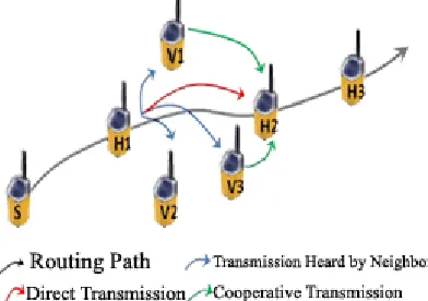
In most protocols wireless communication standard, communications are considered as if they were point to point. In fact when a node transmits a packet on a wireless channel, the packet is not heard only by the destination, but also by the neighbors of the sender and the destination and especially their common neighbors (Note here that by abuse of language in the current sensor networks, the term refers frame package when lies in two packets and when lies in three). In a classic case, when neighbors heard a transmission that is not their destiny, they throw the packet silently. In the case where the direct channel between the source
[image:5.612.331.527.390.528.2]and the destination is disrupted, the source is required to forward its packets on this poor channel and make several attempts retransmissions. The cooperative communication proposes a remedy for that. Take for example the case of Figure 5. The channel between the two nodes H1 and H2 is disrupted but their common neighbors V1, V2 and V3 have better channels. When H1 sends a packet, it is understood by H2 but also by V1, V2 and V3. If an error on H1-H2, neighbors can help by forwarding the packet on a channel better. This communication is called cooperative relaying. Generally cooperative relaying takes place in three stages. Direct transmission is the phase in which the source transmits the packet over the forward channel. Then comes the selection of the relay, one of the neighbors is chosen according to one or more criteria to become relays assist the source. Finally, it comes the cooperative transmission in which the relay forwards the packet to the destination cooperative channel.
Figure 5 - Cooperation and types of channels
Like any other technique, cooperative communication has advantages but also disadvantages. Among these advantages we quote:
- Less Infrastructure: Sharing neighboring antennas increases the utilization of equipment;
- Cost: Reuse of antennas avoids the deployment of new nodes on the network and thus reduces network costs.
In exchange, cooperation raises several challenges. The involvement of other nodes in the communication requires the resolution of several issues:
- Timing: Several cooperative communication protocols using several relays at the same time. This requires a high level of synchronization which complicates maintenance of the protocol;
- Selection of relay: Each cooperative protocol must provide a mechanism to select the best relay among neighbors present;
- Traffic control: the use of cooperation increases traffic control. Cooperative protocols require additional traffic management and synchronization for the relay selection process.
3.1. Technical Cooperation
The techniques of cooperative communications are organized into two major groups: protocols and regenerative relaying protocols transparent relay. In the transparent relay, the signal is relayed as received without any modification. In this family of techniques, we can include: Amplify and-Forward (AF) [21, 22] or Linear Process-and-forward [23]. Regenerative relaying protocols modify the received signal before passing. In this family, we can cite the protocols Estimate-forward [24] Compress and-Forward [25] where Decode-and-and-Forward (DF) [26]. In general, regenerative techniques are more efficient than transparent technical and require much more computing capacity. [27] In all cases, the modeling of the signal transmitted and received by the source, relay and destination are modeled in the same way. The received signal from S, R and the direct transmission of n symbols, can be modeled by the following formulas:
YR[n] = αS,RXS[n] +WR[n] (2.10)
YD[n] = αS,DXS[n] +WD[n] (2.11)
XS[n] represents the signal transmitted by the source and YD[n] signal (YR[n] respectively) represents the signal received by the destination D (respectively by the relay R) signal.
α
S
, R andα
S
, D represent the effect of the channel on the transmitted signal S (attenuation, distortion ...) signal. The signal transmitted by the relay of the cooperative channel is modeled by the following formula:YD[n] = αR,DXR[n] +WD[n] (2.12)
In what follows we focus on two techniques most used relays, namely Decode-and-Forward and Amplify-and-Forward.
Amplify and Forward
Amplify-and-Forward (AF) [21, 22] is one of the simplest forms of cooperation and most popular [27]. The source transmits the signal in the first place, and the relay amplifies and transmits it to the destination second. The destination thus receives two copies of the same signal transmitted by the source and that the relay. The copy of the signal transmitted by the relay is modeled by the following expression:
XR[n] = βYR[n] (2.13)
Where XR[n] is the n symbol transmitted by the relay R and YR[n] is received by the relay and signal emitted by S and β is the amplification factor. This scheme can be considered as a transmission from two different antennas. However, the relay amplifies the received content as amplifying the noise signal.
Decode and Forward
successfully decode the signal reencodent and try to relay to the destination. In this case, unlike AF, noise is not amplified and a new version of the signal is transmitted.
The signal transmitted by R can be modeled by the following formula:
XR
[n] = ẊR[n] (2.14)Where ẊR[n] is the symbol decoded and re-encoded signal received.
3.2. Maximum Ratio Combining
The technique Maximal Ratio Combining (MRC) allows combining several copies of signal from multiple channels to restore the original signal and combat distortion channel. Indeed, in system diversity order L (where L destination receives independent copies of the same signal) with flow and fixed transmission power, the energy of a copy of a transmitted symbol is 1 / L. The receiver then receives a copy of which the SNR (Signal to Noise Ratio) is the sum of SNR of L copies of the propagated signal. The receiver starts by changing the phase of each copy received to align the phases of all copies. [29] Then, it assigns a weight to each copy according to the quality of the channel which it is derived, those from a robust channel get the strongest weight and those of the lower channels are getting the lowest weight. The receiver then performs a weighted sum of these signals to get the final signal. This combination technique called Maximal Ratio Combining (MRC). The copies of the signal received by the receiver can be represented by the following formula:
Yl
= hlsi + Nl, l = 1, 2, ...,L (2.15)Where si is the transmitted symbol, hl is the complex coefficient of distortion through the channel by copying and Nl is the Gaussian random variable representing the additive noise with variance 2σ2. The signals received by the destination can be represented in vector form as follows:
Y
= hsi + N (2.16)Where Y = [Y1, Y2, ...., YL] t, h = [h1, h2, ...., hL] t and N = [N1, N2, ...., NL] t. If a perfect estimate of the link quality is assumed, demodulation is accomplished using the following formula:
𝑋= ℎ∗
‖ℎ‖𝑌 (2.17)
ℎ ∗ represents the vector conjugate and transpose.
ℎ.Substituting 2.16 in 2.17, we obtain:
𝑋= ‖ℎ‖ℎ∗ (ℎ𝑠𝑖 + 𝑁)
=‖ℎ‖𝑠𝑖+ ℎ∗
‖ℎ‖𝑁 (2.18)
The complex Gaussian noise ℎ∗
‖ℎ‖𝑁 variance 2σ2.
This is an overview of MRC, more details can be found in [29].
4. CONCLUSION
We briefly describe networks sensors and a number of applications and challenges. We explained below, the cooperative and its various technical communication. Then we presented MRC technique used to combine multiple packets from a cooperative communication. For our future work, we will focus on the cooperative solution we have developed to monitor the status of a heart patient remotely.
REFERENCES
[1] G. Kramer, I. Maric, and R. D. Yates, “Cooperative communications,” Found.
Trends Netw., vol. 1, pp. 271–425, August
2006. [Online]. Available: http://dl.acm.org/citation.cfm?id=1295178.1 29517
[2] J. Laneman and G. Wornell, “Distributed space-time-coded protocols for exploiting cooperative diversity in wireless networks,”
Information Theory, IEEE Transactions on,
[3] “802.15.4 specification.” [Online]. Available :http://standards.ieee.org/getieee802/downlo ad/802.15.4-2003.pdf
[4] M. C. V. Dr Ian F. Akyildiz, Wireless Sensor
Networks, ser. Ian F. Akyildiz. John Wiley
& Sons, 2010.
[5] P. Juang, H. Oki, Y. Wang, M. Martonosi, L. S. Peh, and D. Rubenstein, “Energy-efficient computing for wildlife tracking : design tradeoffs and early experiences with zebranet,” SIGPLAN Not., vol. 37, pp. 96– 107, October 2002. [Online]. Available: http://doi.acm.org/10.1145/605432.605408
[6] “Center for coastal margin observation and prediction,” 2011 (accessed September 22, 2011). [Online].Available: http://artificialretina.energy.gov/
[7] G. Werner-Allen, K. Lorincz, M. Ruiz, O. Marcillo, J. Johnson, J. Lees, and M. Welsh, “Deploying a wireless sensor network on an active volcano,” InternetComputing, IEEE, vol. 10, no. 2, pp. 18 – 25, march-april 2006. [8] D. Malan, T. Fulford-jones, M.Welsh, and S.
Moulton, “Codeblue : An ad hoc sensor network infrastructure for emergency medical care,” in In InternationalWorkshop on Wearable and Implantable Body Sensor Networks, 2004.
[9] T. Gao, C. Pesto, L. Selavo, Y. Chen, J. G. Ko, J. H. Lim, A. Terzis, A. Watt, J. Jeng, B. rong Chen, K. Lorincz, and M. Welsh, “Wireless medical sensor networks in emergency response : Implementation and pilot results,” in Technologiesfor Homeland
Security, 2008 IEEE Conference on, may
2008, pp. 187 –192.
[10] “Artificial retina project,” 2011 (accessed September 22, 2011). [Online]. Available : http://artificialretina.energy.gov/
[11] L. Krishnamurthy, R. Adler, P. Buonadonna, J. Chhabra, M. Flanigan, N. Kushalnagar, L. Nachman, and M. Yarvis, “Design and deployment of industrial sensor networks : experiences from a semiconductor plant and the north sea,” in
SenSys ’05 : Proceedings of the 3rd
international conference on Embedded
networked sensor systems. New York, NY,
USA : ACM, 2005, pp. 64– 75.[Online].Available:
http://dx.doi.org/10.1145/1098918.1098926
[12] W. Dargie and C. Poellabauer,
Fundamentals of Wireless Sensor Networks :
Theory and Practice, ser. Wireless
Communications and Mobile Computing. John Wiley & Sons, 2010. [Online]. Available:
http://books.google.com/books?id=8c6k0EV r6rMC
[13] “Zigbeef llc,” 2011 (accessed September 22, 2011).[Online].Available:
http://inknowvation.com/node/16096
[14] M. M. Terrance J. Dishongh, Wireless Sensor Networks for Healthcare Applications, 1st ed. Artech House, 2009. [15] I. Stoianov, L. Nachman, S. Madden, and T.
Tokmouline, “Pipeneta wireless sensor network for pipeline monitoring,” in
Proceedings of the 6t international conference on Information processing in
sensor networks, ser. IPSN ’07. New York,
NY, USA : ACM, 2007, pp. 264–273. [Online]. Available: http://doi.acm.org/10.1145/1236360.123639 6
[16] www.xbow.com, “Micaz 2.4ghz,” 2010 (accessed August 14, 2010). [Online]. Available:
http://www.xbow.com/products/Product_pdf _files/Wireless_pdf/MICA2_Datasheet.pdf [17] E. Shih, S.-H. Cho, N. Ickes, R. Min, A.
Sinha, A. Wang, and A. Chandrakasan, “Physical layer driven protocol and algorithm design for energy-efficient wireless sensor networks,” in Proceedings of
the 7th annual international conference on
Mobile computing and networking, ser.
MobiCom ’01. New York, NY, USA : ACM, 2001, pp. 272– 287.[Online].Available:
http://doi.acm.org/10.1145/381677.381703 [18] A. Sinha and A. Chandrakasan, “Energy
aware software,” in VLSI Design, 2000. Thirteenth International Conference on, 2000, pp. 50 –55.
[19] A. Narula, M. Trott, and G. Wornell, “Performance limits of coded diversity methods for transmitter antenna arrays,”
Information Theory, IEEE Transactions on,
vol. 45, no. 7, pp. 2418 –2433, nov 1999. [20] T. Cover and A. Gamal, “Capacity theorems
for the relay channel,” Information Theory,
IEEE Transactions on, vol. 25, no. 5, pp.
[21] J. Laneman, D. Tse, and G. Wornell, “Cooperative diversity in wireless networks : Efficient protocols and outage behavior,”
Information Theory, IEEE Transactions on,
vol. 50, no. 12, pp. 3062 – 3080, dec. 2004. [22] S. Yang and J.-C. Belfiore, “Towards the
optimal amplify-and-forward cooperative diversity scheme,” Information Theory,
IEEE Transactions on, vol. 53, no. 9, pp.
3114 –3126, sept. 2007.
[23] B. Talha and M. Patzold, “Channel models for mobile-to-mobile cooperative communication systems : A state of the art review,” Vehicular Technology Magazine, IEEE, vol. 6, no. 2, pp. 33 –43, june 2011. [24] R. Dabora and S. Servetto, “On the role of
estimate-and-forward with time sharing in cooperative communication,” Information Theory, IEEE Transactions on, vol. 54, no. 10, pp. 4409 –4431, oct. 2008.
[25] G. Kramer, M. Gastpar, and P. Gupta, “Cooperative strategies and capacity theorems for relay networks,” Information
Theory, IEEE Transactions on, vol. 51, no.
9, pp. 3037 – 3063, sept. 2005.
[26] M. Yu and J. Li, “Is amplify-and-forward practically better than decode-andforward or vice versa ?” in Acoustics, Speech, and
Signal Processing, 2005. Proceedings.
(ICASSP ’05). IEEE International Conference on, vol. 3, march 2005, pp. iii/365 – iii/368 Vol. 3.
[27] M. Dohler and Y. Li, Cooperative Communications : Hardware, Channel and
PHY. Wiley & Sons, February 2010.
[28] A. Nosratinia, T. Hunter, and A. Hedayat, “Cooperative communication in wireless networks,” Communications Magazine, IEEE, vol. 42, no. 10, pp. 74– 80, oct. 2004. [29] A. Das, Digital Communication : Principles

![Figure 3 - Supervision of water level [15]](https://thumb-us.123doks.com/thumbv2/123dok_us/8914475.961039/3.612.103.263.303.443/figure-supervision-water-level.webp)