(
· i
..
~!'ll:". 'I£-.._:..,...~'111~ .• ~.---.: ~111'::.~~~ ItLS2 "-'--~tn...--~·~~~~~= ____ ~"'~IlI!IIr;"""",,,_oe.~p[flr~~S/
FAMILY DECTAPEFIELD SERVICE TECH MANUAL
ADJUSTMENTS FOR DECTAPE ~YSTEMS (Continued)
TO USE: (1 )
(2)
Plug in skew tester AFTER selecting source of V plus, see
NOTES on S3 and TO USE: (5), 53.
Calibrate. See NOTES on 51 and TO USE: (5),53.
(~) Select correct split winding, see NOTES on S2 and TO USE:
(5), S2.
(4) Skew Test
A. Zero Skew Tape Available: (Certified DECtapes are not
zero skew. They may· have a l~ sec skew.) Run tape
across head in normal manner. Gain of tester is enough
to give clipped sine wave out. About 10V PIP. Go to
step 4C. This skew is real.
B. No Zero Skew Tape Available. Clean tape head and guides.
(4~E) Format Tape. Reverse tape so oxide side is up. (4-F) Now thread this tape from take-up reel across head
with oxide up onto original supply reel. Move tape in
local mode. Go to step 4C. The skew indicated is twice
real skew.
C. Skew is measured by measuring the time difference between
the two signals crossing a given reference line. Figure
1. To test skew; with tape in motion, depress lightly on
the back edge of the tape on the right or left sides of
the head. Record whirih side causes the skew to increase
when pressure is applied to 'one side or the other. If
D.
the real skew is greater than 2/-4... sec, the head should be
deskewed. This tolerance will apply to both TU5S and Tu56
transports to gain an added factor of interchangeability
of tapes. I f the head is to be deskewed, i t should be taken
as close to zero as possible. If a non-zero skew is used,'
i t must be formatted after each attempt to deskew.
To deskew:
1. Remove head and thoroughly clean back of head and
mounting surface of ail dirt, glue, skew shims, etc~·
Remount head and redo 4A or 4B as applicable.
2. I f shimming is necessary, magtape reflective marker
(DEC #29-15191) is acceptable. Place the marker on
~.
the back of the head on the edge of the side which
caused the skew to increase in step 4C. (For TU56.
heads, the reflective tape must be placed only below
the mounting screw.) Remount head being careful not to
~ .... ,"r,,~~-_::'"""l2J_~,-..:;,r=-a~~~_"Z!mI_osm:laIIe-:l" _ _ zmm_~ ... __
-nt='r-. I ' I
I
PDP..",S/S
DECTAPE(
FIELD SERVICE TECH MANUAL.
ADJUSTMENTS FOR DECTAPE SYSTEMS (Continued)
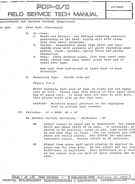
TO USE: (4) Skew Test (Continued)
E. To Clean:
1. Heads and Guides: Use DECtape cleaning solution
generously on the head, wiping dirt wi tho clean,
lint free towel (Kimwipe).
2. Guides: Disassemble guide from plate and
thor-oughly clean with solution all parts including wear plates, studs, springs, spring holes and guides themselves.
3. Tape: Place doubled clean, lint free towel over
head; thread tape over tow~l; place free end of
towel over tape.
Run tape from end-tp-end at least once in each
direction.
F. Reversing Tape: (Oxide side up)
Figure 4-F-1
Mount normally full reel of tape on right hub and empty
reel on left. Thread tape from bottom of full spool onto
top of empty reel. In local move all tape to left reel.
This places oxide side up for skew test.
CAUTION: Maintain manual pressure on the supplying
reel to prevent tape runaway.
(5) Switches: NC
=
DOWN NO = UPSl (Middle Switch) Calibrate - NO/Normal - NC
NO Select signal to lower amp to compensate for internal
drift and phase shift of op amps. To calibrate, put
switch in NO position, scope in Add, tape oxide side
up and move tape in local. The two signals are 1800
phase and should cancel. ADJ 10KPOT for smallest
resultant signal. Return switch to NC position.
NC Signal from other half split winding is applied to
lower amp for skew test. Do not adjust pot for any
difference in amplitude. This difference is a result
of low signal from one half of split winding due to sket-l.
~
9 OF16f1
~AGE
REVISION 0 [[pUBLICATIONDI~TE
February: 15, 197: ) [image:2.615.34.591.23.780.2]ADJUSTMENTS FOR DECTAPE SYSTEMS (Continued)
TO USE:
TU55/56
(5) Switches (continued)
S2 Top Switch: Select split wi~ding, due to different vendors assigning different pins for head connection. I f switch is in wrong position, SlG2 will be twice amplitude of SlG1 in normal position of Sl, when oxide side up. I f oxide sid~ is down, a phase shift plus skew will result.
S3 Bottom Switch: For compatibility to R series transports NC-- +5V i f applied to V plus.
NO-- +10V is divided to +5 for V plus.
CAUTION: This selection is to be made before voltages are applied.
Skew Tester may be placed in any empty slot which has +5 (or +10), -15, and ground in pins A2, B2 and C2 respectively.
Attach female data cable from head to male of tester.
PARTS LIST:
NOTES:
MC1709CG
220 011M 1/4W 5% 4.7K 1/4W 5% 1.5K 1/4rl 5% 22K 1/4W 5% 10K POT
470K 1/4W 5% ·330 OHM 1/2W 5%
1N753A
22pf 100V 5% 10pf 100V 5% .01mf 100V 5% 6.8 mf 35V 20% 1 PST 6 AT1-T2 Ampheno1
19-9344 - E1 through E4
13-0271 13-0447 13-0391 13-1808 13-9143-10
13-2398
13-0296
11-2421
10-0021 10-0006 10-1610 10-0067
12-1168
133-022-03 12-2909
680 OHM 1/2W 5% 13-0347 1. Ampheno1 Pin Assignments
-pin A Skew Tap. -Pin D Center Tap.
-pin B solid winding on Western Magnetic head. Split winding on Brush head.
-pin C Split winding on Western Magnetic or General Instrument. Solid winding on Brush.
Split winding for skew measurement.
~100~~
PAGE HEVISION .~
lJ
PU3L1C/\TION DATE February 15,~9i}
(
,
DECTAPES
FIELD SERVICE TECH MANUAL
tliC!025i.UCW ili&C za ESi!Sl!d(,'M"
ADJUSTMENTS FOR DECTAPE SYSTEMS (Continued)
Notes: (continued)
2. M series use NC position of 83 (+5 applied to A2).
R series use NO position of S3 (+10 V applied to A).
j. i El-E4 MCl709 CG. Pin 4 = V minus 'Pin 7
=
V plus.unless otherwise noted resistors are in OHM, l/4W. 5%
4. MC1709 CG.
Pin side.
1
E-5. Sl = calibrate/normal
S2 = select split wina~ng
o
i5
~
rjg
G>mfTl
~~
!-.o
"'~
"
]l~
~;-.
in
Z
-.~i I]> tJ
Q
0
1110"
r.:~ tTl _tJ<
'TIiU>0,'0
~
zYI
4 f-tiC)
o
ZI"U
a
c:
91 ~.~
,,>
v~
-(0
ZjZ
P
IO:ol~
nrri
~I
'"ll~I~
»Ici
ff)IPJ
~F.
0
:
"""'
-f'"
.L
r-Lr-a
Ull\tl
m
-i ~
(f)
"--"
f
---
_...
1"--"""
;
,
~~ANNeL
'
1 '
-...
C~-ANNE~ ...
"Z.
~"
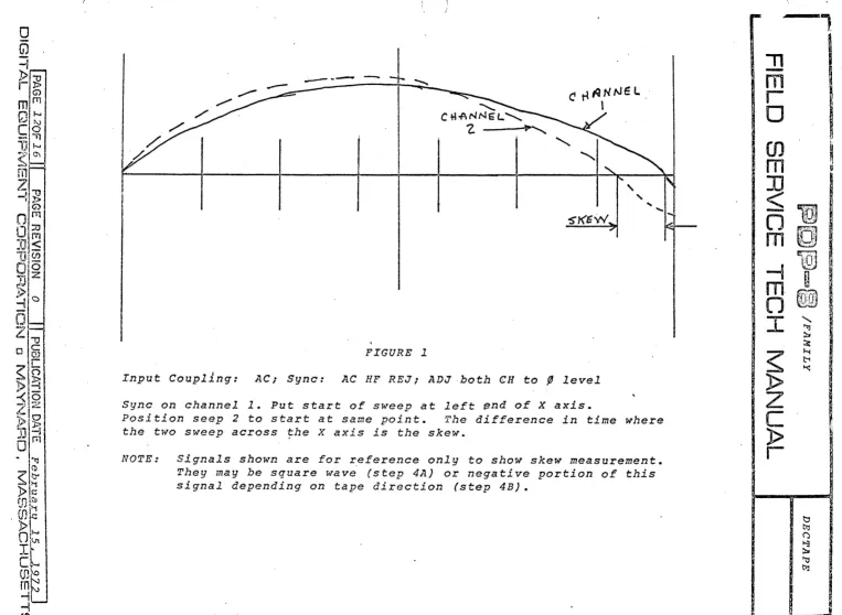
FIGURE 1
Input Coupllng: AC; Sync: AC HF REJ; ADJ,both
eH
to , levelSync on channell. Put start of sweep at left ~nd of X axis.
Position seep 2 to start at same point. The difference in time where
the two sweep across the X axis is the skew.
NOTE: Signals shown are for reference only to show skew measurement.
They may be square wave (step 4A) or negative portion of this
signal depending on tape direction (step 4B).
r---"
"
-
m
r
o
en
m
~
fjlJl
mD
~I::nl
-I
~"m,
,
.
~
O[Q@
I
~
»
z
c
[image:5.793.10.773.23.581.2]»
r
...
'"ll
~
~
I--t
~ ~
~
t:J ~ ~ ~
~
t:J
,
!
I
J
-:l
.!~
~
>1""0
->
~l~
l:!f-...
'.I I....J-10
--!-,,
":,>l"~,,,' r-:.l
,-1.'1
~p,~O)
111
~'~
J~
{!"
"I
rn,'1
1,'::;
') (l,)
jl§ll
] I
;10
p
~G
:Q
.I~I
1(>I.>
Il~ 'j(5
;Iz
:p~
'!-f
;!!"i1!
~ I
.~
-r,
:'Ij~~
-..
~) 1...: _C'i',. "'n
"to "'J '\ ..
)b
~
C}»
1
!N~ ~
,. \ I'~~I~ ~
,§J
-I
Q
I i
\
r--.
i
L
O'l.loe 5 IDt: v( P
~ ~ 00 0 U T P fA TAg 0 I.(
r
~" p / ?/~-...
(
~-
SKt5WI
b~/Dt£ $I/)~
j}oWI'I. l?
~
() ()
C tl "( f? tI 7 ,4 8 (HI T 10 V f / P.These pictures are for reference only; however can be used to illuatrate a point.
Given: Tape: Moving Forward
Channel 2 leads channell as shown.
If tape is reversed, channel 2 should lag channell, as shown with dotted lines, the same amount as i t leads going forward. If this condition is ~ot met, either amount is different or does not swap
from lead to lag~ It indicates faulty guides ~hich must be cleaned
or replaced.
.----'\
"
-
m
l
r
o
m
m
~
O
-~
_','U
~s~
m
D
~
rri
11
~
O
m
",~"f;i" J-:.'1..:'-:.'~
T
"-...c.... ~
~
l>
Z
C
l>
r
~
~
~
/:'i
~
t::1
ttj (')
~3
~I '\J
ttl
i
·
0
(j)
-i
»1"'0
rl>
G>
mlrn
~'
,,
'
[I~
- i ' l
1]1---0
7~ ~
m ;
Z
-11;g
G)
Olm
Q::r.J
(T1
IJ<
M
-tJ ~
Dig
"'0 .:;.
,/-
-1>
-;
',
\0
o
Z~
NORMALo
~.
E Nt PT'I~ ~
REf:ll>~
-<
-I
Z,~
)> ~~
JJ
-l -"O·fTl
I
D'-~~
i
»~
mm~
I
.t:.m
.
E ..
VJ~ 'l1
»1
~F
cL
(J)~
~tJ
-ien
Link Tape:
Q
TAPE FLOW
TU55/56
Reverse Tape
NORMAL
FtALL
RE"EL
Put normal full reel on left hub, empty on right
hub. Thread from bottom of left to top of right.
In local wind all tape onto right reel.
r
. . -... "\
"
-
m
r
o
m
m
1
~
,..,
~ , ,,-m
~
~~
-
,
'
,
:
'
i
~'
.
'
,
~
-1
~
~
"
m
.
~
"
~ ~
l J ~. "
I
~
»
z
c
»
r
"
~ ~::::
\-.f
f:-i
~
I
~
I
c '
• tl I?
~ '
() .
~
.
~ ~
'
~
i
~ I~-'.:lir.ok _ _ _ """"""a.::r'_""
.'£"'<'"!"---
_~~~'~.c,3lI!III!:':iI _ _ ~~"""""'~--""""-~=...,.C&Zt~!b"( I
C
-::r
t
("'(
\I') \.E (\... ...t
<to \(\
':;j \on
<-
:S'ct. 1-£
(..\.
\u
c:a::.
\ ,_
.. /~[O~~~
/FAMILYFIELD
SERVICE TECH MANUAL
~
\U
~
V\
\U
\-o
~~\lJ
w~
\I)
Q
<t
\lJ
::r:
r-\ \1\ \!)"
(L
- t \J'\
:s
I-DECTAPE
?! 0.1-;J iJ /'./ A' 0 ;;J
.;:?7t:/W;J.:l
o
G1
-i
PI
'"0r~
ml~
~~O\
---n
VI-/ 0 \
~
m
I
LI-o
--1Ii>
QOm
O~
1J<
lJ~0
0~Zl
• t f
-1. c
o
Z
IJf;\
C
a
w v,.7' C
0
~ ~i
<)v ·
~~
ZG;.
p~ JJ~
Om
'"ll CD~ ~
l>
~ill ~
(DtC
»
l-n
~ ~"l...
I
CI-(J)~
m
r-v -I-i
en
V\
"
m~'
-\
tn C/\-l
rn
;Q,,"'.'.
~
~ 1"\
~ <:)
~ \
-:t:~
g. <:)
. - ' ~t'l"')
<~
~o
No
N~
,~
r-l~
I~o-l
"
J,.
C.!~r>.
~
U
v-I-L
NO:uP $1.._ fOP ~~ er(. (-oJ
q
I
51
f!No:t..tP
M\DOLC
swlTC. H
,
1
1..'20
'Z.Zo
1..2D
, 2 0
~,
22K
vpt..rJS
V f{\INU, S
"lZK
" PLU"
2.U>Q'!>
f'+ K~Ul
f----::
f lJ.
~
I
.Of/,,-t 10 rf:l
V MINUS
PJrI~2.
-L
3~"O
"til/NUS?ltll:l2
"v
I I
~7
IN7S3APIIJA2
LJ7
0KV Pz..u..,5
I
I
V MINUS
Ll1°1{
V PJ.
u.s
_-~-CIZ
t./.7K
I
1
t-1"5
l/ " MINc/'~5)~
<.
61..\.(£
Sl6 J
RfO
V PLIAS
we.
~
c. S "3" tV 0 :: ./.L P
-'sv
~1Fft·
II'
+5"
o R
-flo
v
I• 0
~-r
I
j) "80"""0
M Ir 5wtT£.tI
• 0 p~
----.
,
----
'
1
"
-
m
r
o
,
i
~~
I
Iffi
i
~
!
fj
~
i
g
m
,
(J~'
"
.
'
".
}:!"
I
-'~
-.
~
m~.
I
(1
~¥'!,', "~:;) ~, ill ,~,i
11
I
~
, ~ ~