M SERIES
K SERIES
PART I
MODULES
A SERIES
B, R, W SERIES
POWER SUPPLIES
PART II
HARDWAREHARDWARE
ACCESSORIES
.PART
III
THE
\
LOGIC HANDBOOK
FLIP CHlp™ MODULES
1970 EDITION
Copyright
©
1969, 1970 by Digital Equipment Corporatio,nDigital Equipment Corporation makes no representation that the interconnection uf its modular circuits in the manner described herein will not infringe on existing or future patent rights. Nor do the descriptions contained herein imply the granting of licenses to make, use, or sell equipment constructed in accordance therewith.
FOREWORD
This sixth edition of the Logic Handbook is your guide to the most extensive array of logic capabilities, hardware, and applications information ever offered by Digital Equipment Corporation. Here you will find a wealth of useful infor· mation on the latest techniques and products available for implementing your electronic logic designs for instrumentation, computer interfacing, data gather· ing, or control. The handbook is a basic reference for anyone involved in specifying, designing, manufacturing or using solid,state logic.
The Products
The M Series TTL integrated circuit modules are featured in this edition. The M Series line has again been expanded and now includes over 85 modules. In addition to this comprehensive array of basic logic and functional logic modules, the general·purpose M Series line also has increased its computer interfacing capabilities. Additions include four new M Series bus interface modules, an input multiplexing module, and an entirely new section on inter· face modules for the PDp·l1.
The K Series product offering has also been expanded. Four new modules are described to bring the total K Series to over 60 modules. A new K Series mounting panel is offered here for the first time. K Series descriptions have been abridged in this edition to provide space to more fully describe the expanded M Series line. However, full and complete descriptions of all K Series modules offered in this book are available in the Control Handbook. Use the handy reply card attached to this book to order your copy. All of the K Series application information plus many new application notes are also available in the Control Handbook.
A complete line of A Series analog·to·digital modules is described here in-cluding seven functionally complete digital-to-analog converter modules as well as multiplexer and operational amplifier modules.
An expanded section on Digital's increased wire wrapping capabilities is in-cluded in this edition. This section not only simplifies the procedure for using our wire wrap capabilities but also announces new reduced prices for the service.
In this edition, also, is a complete description of the K Series Logic Lab - a device designed for use with K Series modules for building prototype systems and as an effective tool for learning solid-state control logic.
This edition of the· Handbook includes an abridged section on all of our major negative logic modules ... the R, B, and W Series.
These module descriptions will be of particular importance to designers who are preparing interfaces to most of Digital's negative bus computers such as the PDP-9 and 8 families.
Digital's complete line of power and hardware accessories provides everything needed to put your designs into action, from connector blocks to mounting cabinets. Power supplies, connector block variations, mounting panels, blank module configurations, connector cards and a complete line of computer, grade cabinetry are among the well over 100 different hardware, power, and accessory items described 'in this edition of the Logic Handbook.
Seven complete M Series applications notes and dozens of useful design notes have been included to help you easily design custom systems making this one of the most informative electronic handbooks available.
The Company,
In a little over twelve years, Digital has become a major force in the electronics industry. The company has grown from three employees and 8,500 square , feet of production floor space in a converted woolen mill in Maynard, Massa· chusetts, to an international corporation employing more than 5,000 people with well over one million square 'feet of floor space in a dozen manufacturing, sales, and service facilities around the world. In addition to the corporate headquarters in Maynard, other Massachusetts manufacturing facilities are located in Westfield, Westminster, and Leominster. Internationally, Digital has manufacturing plants in Puerto Rico, England, and Canada.
From its beginnings as a manufacturer of digital modules, the company has now grown to the point where it is the world's largest manufacturing supplier of logic modules and the third largest computer manufacturer, by number of installations, in the industry. Digital's rise as a leader in the electronics in· dustry began in 1957 with the introduction of the company's line of electronic circuit modules. These solid·state modules were used to build and test other manufacturers' computers. A year later, Digital introduced its first computer, the PDp·I. The PDp·l heralded a new concept for the industry - the small, on·line computer. And the PDp·l was inexpensive - it sold. for $120,000 ' while competitive machines with similar capabilities were selling at over $1 million. But the PDP-l was more than a data processor; more than just a tool to manipulate data. It was a system that could be connected to all types of instrumentation and equipment for on-line, real-time monitoring, control, and analysis. It was a system with which people and machines could interact. Also, in 1958, Digital introduced the Systems Modules', high-quality, low-cost solid-state digital logic circuits on a single printed circuit card. Today, elec-tronic modules like the ones Digital introduced are used in most elecelec-tronic equipment, from computers to television sets.
In 1965, Digital announced the first of the FLIP CHIP module lines. These highly reliable modules include cards for internal computer logic, interfacing, control and analog-to-digital conversion.
This year, Digital introduced a new line of computers, the PDP-ll, which complements Digital's other two small computer lines, the PDP-8 and PDP-12_ The PDP-ll's modular construction and the Unibus concept make it unique_ Digital produces over two million modules a year, making it the world's largest manufacturing supplier of logic modules_ Digital's sales engineers in over 60 offices around the world and applications engineering staff at the home office are ready to help you with your most difficult or complex applications_ They are all listed on the inside back cover_ Give us a call.
ACKNOWLEDGEMENTS
It is impossible to properly acknowledge the efforts of the hundreds of indi-viduals involved in writing and producing a Handbook of this complexity_ A few individuals, however, deserve to be singled out Among those are John Bloem and Joe Orlando who spent many long days preparing the technical informa-tion for this Handbook as well as checking innumerable pages of typeset Also, the production assistance of Frank Coco and the editorial help of Gabe Del Rossi deserve to be acknowledged_ The cover for this Handbook is an original design conceived and executed by Norm Gardner of Boston_
TABLE OF CONTENTS
THUMB INDEX ... " ... " FOREWORD ... .
v
PART I-LOGIC MODULESM SERIES: INTRODUCTION AND GENERAL CHARACTERISTICS ... 3 19 26 MOXX-Auxiliary Functions " ... .
M1XX-Gates, Inverters and Decoders .... .
M2XX-Flip-Flops, Counters, and Shift Registers ... .. 54 72 78 M3XX-Delays " ... "... . .. " ... " .... " ... .
M4XX-Clocks ... " ... " ... " .. .. M5XX-Converters ... " ... ..
M6XX-Amplifiers and Output Drivers. M7XX-lnterface, Complex Functions ... ..
Appliques, Logic Symbols .... .. M9XX-Connectors and Terminators ... ..
85 ... 94 . ... 116 . " ... " 148 .. ... "" .. "... .. .... ,,; 152 K SERIES: INTRODUCTION AND GENERAL CHARACTERISTICS .. 164 ... 168 176 . .. 185 MODULE SUMMARIES AND PRICES.
NEW K SERIES PRODUCTS ... " .. M SERIES COMPATIBLE MODULES .. .
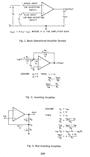
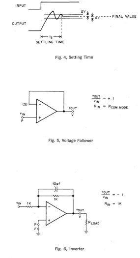
A SERIES: INTRODUCTION AND GENERAL CHARACTERISTICS .. . 221 228 230 235 A123-Positive Logic Multiplexer ... .
A2XX-Operational Amplifiers ... .. A404-Sample and Hold .
A6XX-D/A Conversion ... . A7XX-Reference Supplies
A8XX-A/D Conversion ... .. ... . A9XX-Amplifier Boards " ..
B SERIES: MODULE SUMMARY
R SERIES: MODULE SUMMARy.... ... " W SERIES: MODULE SUMMARY
238 244 246 . .. " .. " .. " ... " ... 248 " ... " ... 251
... 261 ... "" 273 PART 11-POWER SUPPLIES, HARDWARE, AND ACCESSORIES
+5V @ 4 amperes and -15V @ 1.5 amperes ... 302
+5V from 1 to 7 amperes ... 303
Supply Transformers ... 304
Display Supply ... ... , ... 306
Connector Blocks ... 307
Mounting Panel Hardware ... , ... 312
Mounting Panels ... 313
M Series with Supply ... 315
M Series without Supply ... 318
Low Density with Supply ... 318
Low Density without Supply ... 318
K Series without Supply ... ... 318
Mounting Panel Table with Ordering Information ... 319
Module Drawers ... 321
Mounting Panel Frames ... ... 323
Cabinets with Ordering Information ... 326
Wiring Accessories and Tools ... , ... 334
Module Extenders (Troubleshooting) ... 340
Blank Modules ... 342
Cable Connectors and Cables ... ... 344
Wire Wrap Service ... : ... 347
K SERIES LOGIC LAB ... 353
PART III M SERIES APPLICATION NOTES Counter Applications ... 363
Teletype Receiver and Transmitter ... 369
Bus Interfacing ... 377
Equality and Relative Magnitude Detection ... 406
Voltage Control of M401 ... 411
Parity Generation ... 412
INTRODUCTION
The development of monolithic integrated circuits has had an impact on the design of digital module systems. Advantages of small size and high oper-ating speeds made these circuits initially attractive. However, a lower price! performance ratio compared to hybrid or discrete component modules offset the advantages. Recently, significant price reductions in both TTL (transistor-transistor logic) and DTL (diode-(transistor-transistor logic) integrated circuits indicated a re-evaluation was needed.
DIGITAL EQUIPMENT CORPORATION undertook a study of both types of logic, their performance in large and small systems, and their ease of use in system design. The result of this study is the M Series Integrated Circuit FLIP CHIPTM Module.
M Series modules contain high speed TIL logic in both general purpose and functional logic arrays. TIL was chosen for its high speed, capacitance drive capability, high noise immunity and choice of logical elements. High per-formance integrated circuit modules are now available at approximately one half the price of their discrete or hybrid counterparts.
GENERAL CHARACTERISTICS
M Series high-speed, monolithic integrated circuit logic modules employ TTL (transistor-transistor logic) integrated circuits which provide high speed, high fan out, large capacitance drive capability and excellent noise margins_ The M Series includes a full digital system complement of basic modules which are designed with sufficient margin for reliable system operation at frequencies up to 6 MHz_ Specific modules may be operated at frequencies up to 10 MHz_ The integrated circuits are dual in-line packages.
The M Series printed circuit boards are identical in size to the standard FLIP CHIPTM modules. The printed circuit board material is double-sided pro-viding 36-pins in a single height module. Mounting panels (H91O and H911) and 36-pin sockets (HS03 and HSOS) are available for use with M Series modules. Additional information concerning applicable hardware may be found in the Power Supply & Hardware and Accessories section of this handbook.
M Series modules are compatible with Digital's K Series and, through the use of level converters, are compatible with all of Digital's other standard negative voltage logic FLIP CHlpTM modules.
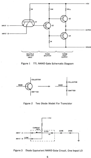
TTL NAND GATE
The basic gate of the M Series is a TTL NAND GATE. Figure 1 is the basic two input NAND gate schematic diagram. The circuit is divided into 3 major sections, the multiple emitter input, the phase splitter and the totem pole output circuit. The two diode model of a transistor shown in Figure 2 will be used in the analYSis of the circuit. A forward biased silicon junction (i.e. diode) gives a voltage drop of about 0.75 volts and a saturated silicon transistor has a collector emitter voltage of 0.4 volts average. These two figures will be used throughout the following discussion.
With either input at the La logic level (O.OV-O.SV) the multiple emitter input transistor will be ON with its base residing at about 0.75
+
0.4 = 1.15 volts. The three diode string consisting of·Q,'s base collector diode, Q,'s base emit-ter diode, and Q;s base emitemit-ter diode will have only 1.15 volts across it and will therefore be conducting only leakage currents (0.75+
0.75+
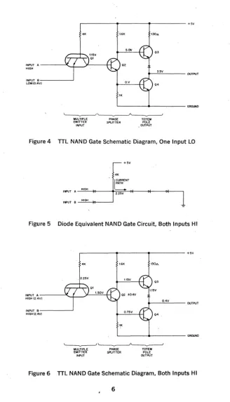
0.75 =2.25 volts required for forward bias). With no current flowing into the base emitter junction of Q" the transistor will be OFF and its collector emitter voltage is alowed to rise. Similarly with no current flowing in the base emitter diode of Q. the transistor is OFF and its collector emitter voltage is allowed to rise. When both Q, and Q. are OFF, Q, is freed to pull the output voltage to a HI level. The voltage levels present in the circuit with one or more La. in-puts is shown in Figure 4.
r---.---.---
+5V4K 1.6K 130A
03
INPUT A ---'".!._~~--___1H 02
... - - - OUTPUT
INPUT B - - - '
MULTIPLE EMITTER INPUT
IK
PHASE SPLITTER
TOTEM POLE OUTPUT
04
Figure 1 TTL NAND Gate Schematic Diagram
COLLECTOR
BASE BASE
----<C>
EMITTER
Figure 2 Two Diode Model For Transistor
CURRENT
f'"
PATH- Oi5V- - ~
INPUT A---~~-~==~~~~O~I~~I~-~--~~--,
r - - - - 02BE Q4BE
I
INPUT B ~(=LO:..:W:..:)---'-#-_ _ _____' I
L _________ .J
Figure 3 Diode Equivalent NAN D Gate Circuit. One Input LO
[image:17.384.29.346.23.572.2]MULTIPLE EMITTER INP\JT
L---~----
__
---G~DPHASE
SPUTTER
[image:18.380.29.357.5.578.2]TOTEM POLE OUTPUT
Figure 4 TTL NAND Gate Schematic Diagram, One Input LO
+5V 4K
I~~
I~T A -"",,,IG,,-" --+>---t';2,"'25;CVC'--<>I---<>I---<>I---,
If.PlJT B ---"""" ... "-jo---~
Figure 5 Diode Equivalent NAND Gate Circuit, Both Inputs HI
r---~---~~---+5V
4K 1.6K
Q3
INPUT A ---'(...J'-~)t----"='-t-l HIGH (2.4V)
INPUT B - - - ' HIGH (2.4VI
MULTIPLE EMITTER INP\JT
t-__ ~O,~4V~ ____ OUTPUT Q4
L-________ ~--~---G~D
PHAsE
SAJTTER TOTEM POLE
OUTPUT
OPERATING CHARACTERISTICS
Power Supply Voltage: 5 volts
±
5% Operating Temperature Range: 0° to 700e
Speed: M Series integrated circuit modules are rated for operation in a sys· tern environment at frequencies up to 6 MHz. Specific modules may be oper· ated at higher frequencies as indicated by the individual module specifica· tions.
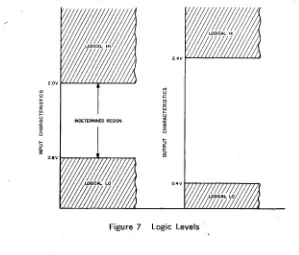
LOGIC LEVELS AND NOISE MARGIN
A gate input will recognize 0.0 volts to 0.8 volts as logical LO and 2.0 volts to 3.6 volts will be recognized as a logical HI. An output is between 0.0 volts and 0.4 volts in the logical LO condition. The logical HI output condition is between 2.4 volts and 3.6 volts. Figure 7 shows diagrammatically the accept· able transistor·transistor logic levels. The worst case noise margin is 400 millivolts that is, an output would have to make at least a 400 millivolt excur· sion to cause an input which is connected to it to go into the indetermined voltage region. For instance if an output were at 0.4 volts (worst case logical LO) there would have to be a
+
400 mv swing in voltage to cause inputs connected to it to go into their indetermined region.Input and Output Loading: The input loading and output drive capability of M Series modules are specified in terms of a specific number of unit loads. Typically the input loading is one unit, however certain module!; may contain inputs which will present greater than one unit load. The typical M Series module output will supply 10 unit loads of input loading. However, certain module outputs will deviate from a 10 unit load capability and provide more or less drive. Always refer to the individual module specifications to ascer· tain actual loading figures.
Unit Load: In the logic 0 state, one unit load requires that the driver be able to sink 1.6 milliamps (maximum) from the load's input circuit while main· taining an output voltage of equal to or less than +0.4 volts. In the logic 1 state, one unit load requires that the driver supply a leakage current 40 microamps (maximum) while maintaining an output voltage of equal to or greater than +2.4 volts.
INOETERMINEO REGION
Figure 7 logic levels·
NAND Logic Symbol: logic symbology used to describe M Series modules is based on widely accepted standards. logic symbols and a truth table for the NAND gate are shown in Figure 8.
A~OUTPUT
B~
A-SA B OUTPUT
L L H
L H H
H L H
[image:20.379.31.330.25.280.2]H H L
Figure 8 NAND Gate logic Symbol and Truth Table
The first symbol is visually more effective in applications where two high in-puts are ANDed to produce a low output. The second symbol better repre-sents an application where low inputs are ORed to produce a high output.
TTL AND/NOR GATE
.---~----~~---~---o +vcc
A
B
C o
06
03
~---<l>---o OUTPUT
[image:21.390.27.347.300.507.2]04
Figure 9 TTL AND/NOR Gate Simplified Schematic
Circuit Operation: The basic elements of the TTL NAN D gate are used with-out modification_ The phase-splitter (Q2) is paralleled with an identical transistor (Q6). also controlled by multiple-emitter input transistor which receives two additional inputs. C and D. When either of the input pairs are high. the phase inverter operates to switch the output voltage low. Circuit performance is essentially identical to the TTL NAND circuit.
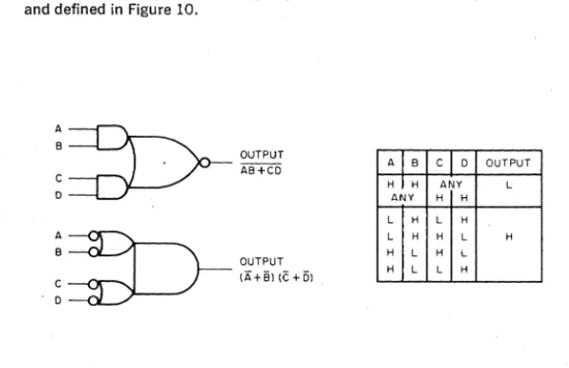
AND/NOR Logic Symbol: The logic symbols for the AND/NOR gate are shown and defined in Figure 10.
:~OUTPUT
C AB +CDo
A B C 0 OUTPUT
H I H ANY L
ANY H H
L H L H
L H H L H H L H L
H L L H
A~
B
OUTPUT ~. (A+Sl(C+Dl
Figure 10 AND/NOR Gate Logic Symbols and Truth Table
: = D - 0 U T P U T
AND/NOR INPUTS TIED RESULTING NOR SYMBOL
Figure 11 NOR Connection of ANDINOR Gate NAND GA:rE FLlP·FLOPS
RS Flip·Flop: A basic Reset/Set flip-flop can be constructed by connecting two NAND gates as shown in Figure 12.
PREVIOUS INPUT
RESULT STATE CONDITION
SET---Q,
I 0 • SET RESET I 0
L H L H H L
H L H L L H L H H H NO CHANGE H L H H NO CHANGE H L L H NO CHANGE o L H H L NO CHANGE RESET---<¥
L H L L H H* H L L L H H*
Ambiguous state: In practice the input that stays low longest will assume control.
Figure 12 RESET ISET NAND Gate Flip-Flop CLOCKED NAND GATE FLlP·FLOPS
The Reset-Set flip-flop can be clock-synchronized by the addition of a two-input NAND gate to both the set and the reset two-inputs. (See Figure 13.) One of the inputs of each NAND is tied to a common clock or trigger line.
SET
CLOCK
o
RESET
A change of state is inhibited until a positive clock pulse is applied. The ambiguous case will result if both the set and reset inputs are high when the clock pulse occurs.
M SERIES GENERAL-PURPOSE FLIP-FLOPS
Two types of general-purpose flip-flops are available in the M Series, both of which have built-in protection against the ambiguous state characteristic of NAND gate flip-flops.
FLIP-FLOP CLOCK INPUT SYMBOLS
The D type flip-flop is a true leading (positive going voltage) edge triggered flip-flop and the D input is locked out until the clock input returns to low. The symbol to indicate this function will be as follows;
D TYPE FL I P FLOP CLOCK
The operation of the J-K type flip-flop is to transfer the information present at the J .and K inputs just prior to and during the clock pulse to the master flip-flop when the threshold is passed on the leading (positive going voltage) edge of the clock pulse. The information stored in the master flip-flop is transfered to the slave flip-flop, and consequentially to the outputs, when the threshold is passed on the trailing (negative going voltage) edge of the clock pulse. The symbol to indicate this function will be as follows;
J K TYPE FLIP FLOP CLOCK
D Type Flip-Flop: The first of these is the D type flip-flop shown in Figure 14 In this element, a single-ended data input (D) is connected directly to the set gate input. An inverter is provided between the input line (D) and the reset input. This ensures that the set and reset levels cannot be high at the same time.
S 1
D
C
R 0
S (DC SET)
,---,
D - - - _ . _ - - - l
I
(SET)
c ---4---~
(CLOCK)
I
I
I
I
L_
}--4----;--0
I
----~
R (DC RESET) NAND GATE EQUIVALENT
SIMPLIFIED NAND GATE EQUIVALENT Figure 14. D Type General Purpose Flip·Flop
The flip·flop proper employs three·input NAND gates to provide for dc set and reset inputs.
D type flip·flops are especially suited to buffer register, shift register and binary ripple counter applications. Note that D type devices trigger on the leading (or positive going) edge of the clock pulse. Once the clock has passed threshold, changes on the D input will not affect the state of the flip·flop due to a lockout circuit (not shown).
[image:24.378.38.340.36.336.2]"MASTER-SLAVE J-K FLIP-FLOP"
The two unique features of a J-K flip-flop are: A) a clock pulse will not cause any transition in the flip-flop if neither the J nor the K inputs are enabled during the clock pulse, and B) if both the J and the K inputs are enabled during the clock pulse, the flip-flop will complement (change states). There is no indeterminate condition in the operation of a J-K flip-flop.
A word of caution is in order concerning the clock input. The J and I< inputs must not be allowed to change states when the clock line is high, the output will complement on the negative going voltage transition of the clock. It is for this reason that the clock line must be kept low until it is desired to transfer information into the flip-flop and no change in the states of the J and K inputs should be allowed when the clock line is high.
The J-K flip-flops used are master-slave devices which transfer information to the outputs on the trailing (negative going voltage) edge of the clock pulse. The J-K flip-flop consists of two flip-flop circuits, a master flip-flop and a slave flip-flop. The information which is present at the J and K inputs when the leading edge threshold is passed and during the clock high will be passed to the master flip-flop (The J and K inputs must not change after the leading edge threshold has been passed). At the end of the clock pulse when the threshold of the clock is passed during the trailing (negative going voltage) edge, the information present in the master flip-flop is passed to the slave flip-flop. If the J input is enabled and the K input is disabled prior to and during the clock pulse, the flip-flop will go to the "1" condition when the trailing edge of the clock occurs. If the K input is enabled and the J input is. disabled prior to and during the clock pulse, the flip-flop will go to the "0" condition when the trailing edge of the clock pulse occurs. If both the J and K inputs are enabled prior to and during the clock pulse, the flip-flop will complement when the trailing edge of the clock pulse occurs. If both the J and K inputs are disabled prior to and during the clock pulse, the flip-flop will remain in whatever condition existed prior to the clock pulse when the trailing edge of the clock pulse occurs.
J I N PUT ----1---1
IOUTPUT
CLOCK
[image:25.382.32.345.349.569.2]o OuTPuT )0( I N P UT -1---1
Figure 16 shows a functional block diagram of a master slave J-K flip-flop using NAND gates. Gates C and D are the master flip-flop. Gates G and Hare the slave flip-flop. Gates A and B are the steering network of the master flip-flop and the steering network for the slave flip-flop is comprised of gates E, F, and 1. The 1 output of the master flip-flop is point X. The operation of the flop will be studied by examining the "1" to "0" transition of the flip-flops, with both the J and the K inputs enabled with a HI level before the clock pulse. When the leading edge of a HI clock pulse occurs, gate B will be enabled with three HI inputs. This will provide a RESET signal for the master flip-flop which will then go to the "0" condition. The slave flip-flop remains in the "I" condition while the clock pulse is HI because gate I is providing a LO signal to both gates E and F, thereby blocking inputs to the slave flip-flop. When the trailing edge of the clock pulse occurs, gate F will be enabled with a HI level at both its inputs and a RESET signal will be provided to the slave flip-flop, which will then go to the "0" condition. The next clock pulse, with both the J and K enabled, would cause the master flip-flop to go to the "1" condition on the leading edge of the clock pulse and cause the slave flip-flop to go to the "1" condition on the trailing edge of the pulse. Figure 16 is a truth table for the J-K flip-flop showing all eight possible initial conditions.
INITIAL CONDITIONS FINAL CONDITIONS
OUTPUTS INPUTS OUTPUTS
1 0 J K 1 0
LO HI LO LO LO HI
LO HI LO HI LO HI
LO HI HI LO HI LO
LO HI HI HI HI LO
HI LO LO LO HI LO
HI LO LO HI LO HI
HI LO HI LO HI LO
HI LO HI HI LO HI
[image:26.379.52.348.228.548.2]UNUSED INPUTS (GATES AND FLlP·FLOPS)
Since the input of a TTL device is an emitter of a multiple'emitter transistor, care must be exercised when an input is not to be used for logic signals. These emitters provide excellent coupling into the driving portions of the circuit when left unconnected. To insure maximum noise immunity, it is necessary to connect these inputs to a source of Logic 1 (High). Two methods are recommended to accomplish this:
1. Connect these inputs to a well filtered and regulated source of +3 volts. Pins Ul and VI are provided on the M113, M117, M119, M121, M617, and M627 for this purpose.
2. Connect these inputs to one of the active inputs on the same gate. This results ina higher leakage current due to the parallel emitters and should be considered as an additional unit load when calculating the loading of the driving gate.
Connection of unused inputs to the supply voltage, Vcc, is not advisable, since power supplies are subject to transients and voltage excursions which could damage the input transistor.
TIMING CONSIDERATIONS
Standard Timing Pulse: In digital system design, a reference for system timing is usually required. The M Series modules M401 or M405 produces a standard pulse which provides such a reference. The standard pulse derived from each of these two modules is shown in Figure 17.
+3.0 :!:O.GV -
-Tf =T,= 15 nsec, NOM.
Tp= 50nsec, NOM. (M401,M602) =110nsec, NOM. (M602 OPTION)
~--_____ Tp ______ ~ I
-
-:-
- ~-I +1.5V NOMINAL 0.0 +0.4 I lOOt. I 1 THRESHOLO
-O.OV - - - -I' - - .1. "'-_ _ _ _ L I - .: _ _ ·1 _ ...L POINT Lot-T f
-J
I.-
Tr--.JNAND Gate and Power Amplifier Propagation Delays: The standard pulse (Figure 17) is distributed throughout a system in negative form to maintain the leading edge integrity. (Since the TTL gate drives current in the logic
a
state, the falling edge is more predictable for timing purposes.) However, the standard pulse is of the wrong polarity for use as a clocking input to the type D and J-K flip-flops, requiring the use of a local inverter. Ordinarily, a NAND inverter is adequate. Where high fan-out is necessary, a M617 Power NAND is preferred.For applications requiring both high fan-out and critical timing the M627 Power Amplifier is available. This module contains extremely high-speed gates which exhibit turn-on times differing by only a few nanoseconds. Simultaneity is desirable in clock or shift pulses distributed to extended shift registers or synchronous counters.
Delays introduced by inverting gates and power amplifiers are illustrated in Figure 18. (Delays are measured between threshold points.)
~
'STANDARD PULSE
I I
I I DELAY (NANOSECONDS)
I+-Ion~ ~Ioff~
I I I
NAND OR POWER ~ ~
NAND GATE ~ ~ ~
, I I I I I . I-'oft~
'"
'otfryp MAX TVP MAX
'8 29 8 '5
--I
r--'"
I IPOWER~
AMPLIFIER I I
M627 I
I I I I 7 - 5
Flip-Flop Propagation Delays: D type flip-flops trigger on the leading or rising edge of a positive clock pulse; the propagation delay is measured from the threshold point of this edge. The set-up time of the D flop is also measured from this threshold point. Data on the D input must be settled at least 20 nanoseconds prior to the clock transition. The advantage of the D·flip-flop, however, is that the leading edge triggering allows the flip-flop AND gates to propagate while the clock pulse is still high. Figure 19 illustrates this situa-tion.
~20".""I·I----NS50EC;:----j
I NSEC I
I ~~T I 1
I I
1
.+ CLOCK
D TYPE FLIP FLOP
I
~30---.j NSEC I
OUTPUT _ _ _ _ _ "
Figure 19. D Type Flip-Flop Timing
JK type flip-flops are, in effect, trailing edge triggering devices as explained previously. The only restriction on the J and K inputs is that they must be settled by the time that the rising edge occurs. Timing is shown in Figure 20.
!.--J
AND K INPUTS MUST BE I STABLE BY THIS TIME1
TRIGGER
PULSE
___ 1
\---FLIP- fLOP OUTPUT
1
--.1
1
l.-
I________ x
Figure 20. J-K Flip-Flop Timing
When using the dc Set or Reset inputs of either flip·flop type, propagation delays are referenced to the falling edge of the pulse. This is due to the inverted sense of these inputs. When resetting ripple type counters (where the output of one flip·flop is used as the trigger input to the next stage) the reset pulse must be longer than the maximum propagation delay of a single stage. This will ensure that a slow flip·flop does not introduce a false transi· tion, which could ripple through and result in an erroneous count.
One·Shot Delay: Calibrated time delays of adjustable duration are generated by the M302 Delay Multivibrator. When triggered by a level change from a logical one to a logical zero, this module produces a positive output pulse that is adjustable in duration from 50 to 750 nsec with no added capacitance. Delays up to 7.5 milliseconds are possible without external capacitance. (See M302 specification.) Basic timing and the logic symbol are shown in Figure 21. The 100 picofarad internal capacitance produces a recovery time of 30 nsec. Recovery time with additional capacitance can be calculated using the formula;
OUTPUT (TYPICAL)
t, Nanoseconds
=
30 C Total (Picofarads) 100~ ~
0.5.~
OUTPUT IL-il-...J
LOGIC SYMBOL
I I
f--t
r - :I I
I I
I I 4 - - -50 nsec MIN.
I
I I
I I
_ , '4--50 nsec TYPICAL I
jf'
: :_50
--~-::
TO750
nsec _____.._J
I. II I TIMING
Figure 21. One·Shot Delay Timing and Logic Symbol
SYSTEM OPERATING FREQUENCY
[image:30.379.40.347.183.425.2]1. A standard clock pulse width of 50 nsec is assumed. This' period is measured from the threshold point of the leading edge to the threshold point of the trailing edge.
2. One flip·flop propagation delay of 35 nsec from the trailing edge of the clock pulse .to the threshold point of the final state of the flip·flop is allowed.
3. Two gate·pair. delays of 30 nsec each are assumed. (A gate·pair consists of two inverting gates in series.) Two gate-pair delays are usually re-quired to perform a significant logic function with a minimum of parallel operations. The two gate-pair delays total 60 nsec.
The time necessary to perform these operations before the next occurrence of the clock pulse is the sum of the delays; 50
+
35+
60, or 145 nsec. Allow-ing 20 nsec for variations within the system, the resultAllow-ing period is 165 nsec, corresponding to a 6 MHz clock rate. This timing is demonstrated inFigure 22. .
GATE GATE CLOCK F/F PAIR PAIR WIDTH DELAY DELAY DELAY IDLE
I " -
n~~c
- t -n~;c
- -n~~c ~
n~~c
- -n;~c--i
I I I I I I
I I I
CLOCK
o
_ __
1:
JK FLIP - FLOP
o
GATE PAIR I
j
o ---~
_ _ _
1:
GATE PAIR 2
o
Figure 22_ Delays Determining System Operating Frequency
Substitution of a D type flip-flop results in a similar timing situation. In a system using both D and J-K flip-flops, note that the D flip·flop triggers on the leading edge of the clock pulse and the J·K flip·flop triggers on the trailing edge. When calculating system timing using D flip-flops, remember that the flip·flop inputs must be settled at least 20 nsec prior to the occurrence of the clock pulse.
LOGIC 1 SOURCE
I
~
'---_ _ _ _ _ M_O_02 _ _ _ _ _ ---I
~
02 E2 F2 H2 J2 K2 L2
MOO2 M2
N2 P2 R2 52 T2 U2 V2
POWER -E-- A2 - +5V -E-- C2 -GRO
To hold unused M-Series TTL gate inputs high, the M002 provides 15 outputs at +3 volts (Logic I), on pins 02 through V2. Up to 10 unused M-Series gate inputs may be connected to anyone output. If a M002 circuit is driven by a gate, it appears as two TTL unit loads or 3.2 rna. at ground.
Power: +5 vat 16 rna. (max.)
SOLENOID DRIVER
M040
V2
I
SE~ES
I
SOLENOID 1-_ _ ... _ _ --'5"-'=2
DRIVER
POWER:
- A 2 - - + 5 V - S 2 - - - 1 5 V
_ C 2 - - G R D
M040 Solenoid Driver
These high current drivers can drive relays, solenoids, stepping motor wind· ings, or other similar loads. The output levels are -2 volts and a more negative voltage determined by an external power supply. One terminal of the load device should be connected to the external power source, the other to the driver output. There are two drivers per module.
Pin V of the driver module must be connected to the external supply so that the drivers will be protected from the back voltage generated by inductive loads. If the wire to the power supply is more than 3 feet long it may have to be by·passed at the module with an electrolytic capacitor to reduce the short over·shoot caused by the inductance of the wire. If pin V is connected to the supply through a resistor, the recovery time of inductive loads can be decreased at a sacrifice in maximum drive voltage capability. Maximum rated supply voltage less actual supply voltage should be divided by load current to find the maximum safe resistance. When both circuits on a module are used, the load current for the above calculation is the sum of the currents.
Outputs: The M040 has maximum ratings of -70 volts and 0.6 amp. Typical delay for the circuit is 5lLsec. No more than two circuits should be paralleled to drive loads beyond the current capabilities of single circuits.
Grounding: High current loads should be grounded at pin C2 of the M040. -15 volt at 9 rna. (max.)
Power: +5 volt at 47 rna. (max.)
The external voltage supply must provide the output current of the two drivers. (1.2 amps. max.)
Note:
Refer to K Series driver modules for increased current drive, increased voltage breakdown or AC current drive capability.
50 MA. INDICATOR DRIVER
M05Q
POWER
_ A 2 - - + 5 V +-S2---15V +-C2--GRD
M050 INDICATOR DRIVER
The M050 contains twelve transistor inverters that can drive miniature in-candescent bulbs such as those on an indicator panel. It is used to provide drive current for a remote indicator, such as Drake 11-504, Dialco 39-28-375, or Digital Indicator type 4908, or level conversion to drive 4917 and 4918 indicator boards (See the Hardware Section.) A low level on the input of the driver causes current to flow in the output.
Inputs: Each input presents two unit loads.
Outputs: Each output is capable of driving 50 rna. into an external load con-nected to any voltage between ground and -30 volts.
Power: +5 volt at 47 rna. (max.) -15 volt at 16 rna. (max.)
Note: For those applications requiring the sinking of current, refer to K Series.
LEVEL CONVERTER
·1
~
L...,;,... _ _ _ _ _ M_O_51 _ _ _ _ _ ---1
~
POWER
+-A2--+5V
+-B2--~15V
+-C2--GRD
The M05l contains twelve level converters that can be used to shift M and K Series logic levels to negative logic levels of ground and -3 volts. A grounded input on the driver generates a grounded output.
Inputs: Each input presents two TTL unit loads.
Outputs: The output consists of an open collector PNP transistor and can drive 20 rna. to ground -6V maximum may be.applied to the output. Power: +5V at 47 rna. (max.); -15V at 16 rna. (max.)
BUS DATA INTERFACE
~
L -_ _ _ _ _ _ M_1_O_O _ _ _ _ _ - - - - I
~
CI
Bl F2
AI E2
EI J2
01 H2
HI L2
Fl K2
Kl N2
JI M2
MI R2
L1 P2
PI T2
NI S2
S1 V2
RI U2
UI POWER
VI - A 2 - - - + 5 V
- C2,TI-.-- GNO
- B 2 - - - - 1 5 V
The loading presented to the negative voltage bus differs from that loading using the standard negative bus modules (i.e., RI07, RIll) in that the data lines are loaded only if the appropriate device is selected. The option select output of the MI02 must be c-onnected to the strobe input pin, CI, of the MIOO.
The enabling line of the MIOO cannot be used as a strobe line. The output signals are indeterminant for a period of 200 nsec after the enabling line has become true.
Inputs: All outputs will drive 10 TTL unit loads.
Conversion: Logic Diagram: An active voltage is a True State, i.e., -3 v or +3v
=
"I".A ground is a True State.
A data input of -3v will yield an output of ground when CI is gated by a positive voltage logic "I" of +2.4 volts.
Threshold switching level: -1.5 v. typo Propagation delay: 40 nsec typo
Power: +5 volts at 60 rna .. (max.); -15 volts at 10 rna. (max.)
BUS DATA INTERFACE
I
SE~ES
I
MIOI
C1
81 F2
A1 E2
E1 J2
01 H2
H1 L2
F1 K2
K1 N2
J1 M2
M1 R2
L1 P2
PI T2
N1 52
51 V2
R1 U2
U1 V1
POWER
-E-,.-- A2 - +5V
The MIOI contains fifteen, two-input NAND gates arranged for convenient data strobing off of the POPS! I or POPS! L positive bus_ One input of each gate is tied to a common line so that all data signals on the second input of each gate can be enabled simultaneously_ The MIOI can also be used as inverters or a 'data multiplexer. All data inputs are protected from a negative of more than -O.S volts.
Inputs: Each data signal input presents one TTL unit load. The common line input presents fifteen unit loads.
Outputs: Each output can drive ten unit loads. Power: +5V at S2 rna. (max.)
DEVICE SELECTOR
I
r-;;l
'---_---'-_ _ _
M_10_2 _ _ _ _ _
- I~
HI
Kl Jl
L1
OPTION SELECT Nl
U2 ENABLE Ml
OPTION SELECT
PI V2
Rl
51
UI
AI M2
P2 IOPI T2
Bl
Cl R2 IOP2
01
EI S2 IOP4
Fl
4 - - - A 2 - - - +5V 4 - - C2. T I - - GRO +3 - _ . - VI
----+
LOGIC I+ -B2 - - - -15V
The MI02 is used to decode the six device address bits transmitted in comple-mentary pairs on the negative bus of the PDP-8, PDP-8/L The outputs of the MI02 are compatible with M Series TTL logic_ The MI02 is pin compatible with the MI03 Positive bus device selector with the' exception of the address inputs. The true state of the BMB outputs of the PDP-8 and PDP-8/1 are defined as ground where the true states of the PDP-8/1 positive bus and PDP-8/l are defined as an active voltage state. This fact requires that the complement of the address bits used for an MI03 must be connected to
As the address complement is tied to the pins 02, E2, F2, H2, J2, K2, an MI03 may be directly sUbstituted for an MI02 when changing from a negative to a positive bus.
Inputs: U2 represents 1.25 TTL unit loads, J1, Ml represents 1 TTL, PI, Rl, SI, Ul, M2 and T2 standard levels of -3 volt and ground. Input load is 1 rna. shared among the inputs that are at ground.
P2, R2, S2, HI and L1 0.2 rna. when V in
=
Ov 0.0 rna. when V in=
-3v Propagation Delay 40 nsec typoOutputs: Kl and Mlcan drive 10 TTL unit loads. AI, 81, Cl, 01, El, F1 can each drive 37 TTL unit loads. U2 can drive 16 TTL unit loads.
Conversion: Logic Diagram. An active voltage is a True State, i.e .. , -3v or +3v
=
"1". A ground is a True State.Power: +5 volts at 130 rna. (max.); -15 volts at 40 rna. (max.)
DEVICE SELECTOR
I
~
' - -_ _ _ ...,..-_M_l_03 _ _ _ _ _ _ •
~
( )
o
U2 OPTION SELECT ENABLE
~ {~~
P
F2 ~--,~ H2
5
J2z K2 - f . - - ' L2
Z
"1J C
--I
(j) N2
HID-
. . KlJl
L1D-
NlMl
P2~I~OP~1---t-t ____ ~
R2~I~O~P~2---t_t ____ ~
S2 ~IO::.:P_4.:._ ____
L __ ../
POWER
.:--- A2 - - -+ 5V __ C2, Tl - GRD
Al
L -_______ Bl
Cl
L -_ _ _ _ _ _ _ 01
El ' - - - Fl
+3V - - - VI - - - UNUSED INPUTS
Inputs: All inputs which receive positive bus signals are protected from negative voltage undershoot of more than
-o.av.
The following inputs each present one TIL unit load 02, E2, F2, H2, J2, K2 HI, Jl, Ll, and M1. Inputs P2, R2, and S2 present 2.5 TTL unit loads. Inputs U2, L2 and N2 each present 1.25 unit loads. These inputs need not be tied to a source of logic 1 whe'n not used.
Outputs: Gate outputs Kl and Nl can each drive ten TIL unit loads.
Pulse buffering outputs Ai, 81, Cl, 01, El and Fl can each drive 37 TIL unit loads.
The Option Select output can drive 16 TIL unit loads. Power: +5 volts at 110 rna. (max.)
DEVICE SELECTOR
'I
~
' - -_ _
-"-_ _
M_10_7_---'
~
,
The MI07 is a device selector which, by the use of extended decoding of the BMB lines 9 through 11, will provide seven discrete lOT pulses. Five additional lOT pulse outputs are provided to allow the user to reduce software require· ments by the combining of lOT codes. The lOT instruction and the lOP times at which the various lOT pulses occur at the module pins are outlined in the following chart:
Module lOT ATIOPTIME
Pin 1 2 4
BH2 1-1 X
BM2 2-2 X
BJ2 3-1 X
BN2 3-2 X
BS2 4-4 X
BK2 5-1 X
BT2 5-4 X
BP2 6-2 X
BU2 6-4 X
BL2 7-1 X
BR2 7-2 X
BV2 7-4 X
-Example: If an IOP-7 is issued, lOT pulses will exist only at output pins BL2 (7-1). BR2 (7-2) and BV2 (7-4). lOT pulses will not exist at any oth,er output pin_
The MI07 also contains two flag flip-flops which may be directly cleared or set. The outputs of the flag flip-flops are connected to the skip and program inter-rupt lines. Interrogation of the flags is accomplished by lOT 1 - 1 for flag 1 and lOT 2 - 2 for flag 2.
The MI07 also provides two inputs to accomplish the "clear the accumulator" function.
~P:
~.
AE2 BF2
AF2 CLA BUS
AH2 AV2
AJ2 AK2 BD. BE.
_ BAZ, AAZ - +5'1
AD' DEVICE ENABLE - { AC2, Be2}- GRD
IOP1 ATI, BTl
AM2 5-' BK2
DECODER
7-' BL'
.-.
AN2
,-.
IOP4
J I
"~"'
AP2 7-2 BR2 ~BSI 4-4 852
CAl
n
)-i
5-4 BT2 )---j SKIPCJI BM89 BUS
AM 6-4 BU2
7-4 BV2
AB' 5MBIO
Lcq
::: I
AC1 5MBIII I
~ ~BR'I'<II'"<:I'"T 1'", Jlr. ? P.1.
AU2
AL2
AS2
I
~
INPUTS: Pins - BD2, BE2, AM2, AN2, AP2, AU2, AS2 Present 1.25 TTL load. Pins - AR2, AT2 resent 2 TTL loads.
Outputs: Option Select Pin ADI can drive 13 TTL loads. Bus driver outputs pins BPI, BSl, and BRI are open collector NPN transistors and can sink 30 mao at ground. The maximum voltage applied to these outputs must not exceed +20 volts and each output is diode protected against negative under-shoot in excess of -0.9 volts.
All other outputs will drive up to 35 TTL loads. Power: +5v at 245 mao (maximum).
FLAG MODULE
I
~
' - -_ _ _ _ _ M_IO_8 _ _ _ _ _ ---'
~
H2 TEST
J2 RESET
SKIP 51
0
K2 SET E PT RI
0
L2 02 M2 TEST
N2 RESET
0
P2 SET C
0
R2 E2 52 TEST
T2 RESET
0
U2 SET C
0
V2 F2
POWER
The MI08 is a single height module and contains three flag flip-flops. Each flag flip-flop may be independently cleared or all flip-flops may be cleared simultaneously.
The output of each flag flip-flop is gateable and are open collector "OR"ed to the Program Interrupt bus ..
The output of each flag flip-flop is passed through a gate and open collector to the skip bus. This facility allows the user to test for a flag.
The "0" side of each flip-flop has been extended to module pins for periph-ral control.
Each flip-flop may be independently set by the application of the leading (positive going voltage) edge of a pulse or level to the clock inputs.
If it is not desired to disable the Program Interrupt gate, internal circuitry is provided which makes it unnecessary to connect these inputs to a source of logic "I".
Inputs: K2, P2, U2, present 2 TIL loads. D2, E2, F2 present 1.25 TIL loads. All other inputs present 1 TIL load.
Outputs: L2, R2, V2 supply 9 TIL loads. RI (P. I. Function) and SI (Skip Function) are open collector NPN Transistors and will sink IOOmA to ground. The voltage applied to these outputs must not exceed +20 volts.
Power: +5 volts at 137 mao (max.)
INVERTER
I~
Mill
Al-D-Bl
K2.-D- L2
C1-D-D2
N1-D-P1
Dl-D-El
M2.-D-N2
Fl-D-Hl
R1-D-S1
E2-D-F2
P2-D-R2
J1-D-K1
V1-D-U1
H2-D-J2
S2-D-T2
L1-D-Ml
U2-D-V2
POWER
<E---
A2 -- +5V
~C2.Tl- GRD
Sixteen Inverters with input/ output connections as shown. Input: Each input presents one unit load.
Output: Each output can drive up to ten unit loads.
NOR GATE
I~
1 . . -_ _ _ _ _ M_ll_2 _ _ _ _ _ ---I
~
.AlD-
. ClL1D-61
DID-El
D2D-
E2HID-
JlH2D-J2
Ml
Fl
L2.D-M2
F2
P1D-Rl
Kl
P2D-R2
K2
T2D-U2
POWER
~ A2~+5V
~.C2.Tl~ GRD
+3V ~ Ul. VI ~ UNUSED INPUTS Nl
N2
Sl
S2
V2
The M112 contains ten positive NOR gates, each performing the function A + B. Pins Ul and VI provide +3 volts, each capable of holding High (Logic 1) up to 40 unused M-Series inputs.
Input: Each input presents one unit load.
Output: Each output can drive up to ten unit loads. Power: +5V at 50 rna. (max.)
NAND GATES
M113.M115. M117. M119
~
CI 91~
'
FIEI
~
F2E2
~.
KI JI~
.,K2
J2
POWER:
~
NIMI
~
2N2
M2
~
51RI
~
52 R2T~2
V2 U2- A 2 - - + 5 V
- C 2 , TI--GRD
+3V--UI, VI-UNUSED INPUTS
M113 2·INPUT NAND GATES
~
.91 01
CI
~
FI JI
HI
~
'L1 NI
MI
~
RI . . UI
51
POWER:
~
2E2 H2
F2
~
K 2 M 2 L2
~
P2 . .52 R2
~
U2 VI
V2
- A 2 - - + 5 V
- C 2 , TI--GRD
AI BI CI 01 02 E2 F2 H2
H2 F2 E2
~
KI JI HI LI
~
N2 M2 L2~
. P2RI PI Nt
~
U2 T2 S2 V2~
POWER: - A 2 - - +5V - - C 2 . T l - GRO
+3 VOLTS - - U1.VI - UNUSEOINPUTS
J2
MIl7 4-INPUT NAND GATES
F1 HI J1 KI P2 K2 L2 M2 N2 POWER:
_ A 2 - - + 5 V MI N1 PI R1 R2 S2 T2 U2
- C 2 . TI--GRO
+3VOLTS_UI. VI--UNUSEO INPUTS
MIl9 8-INPUT NAND GATES
These modules provide general-purpose gating for the M Series, and are most commonly used for decoding, comparison, and control. Each module performs the NAND function A • B - - - N, depending upon the number of inputs_
as inverters.
M113-Ten, two·input NAND gates that also may be used M115-Eight, three·input NAND gates.
M117-c-Six, four·input NAND gates. M119-Three, eight·input NAND gates.
Unused inputs on any gate must be returned to a source of logic 1, for maximum noise immunity. In the Mll3, Mll7, M1l9, M121, M617 and M627 modules, two pins are provided (Ul and VI) as source of +3 volts for this purpose. Each pin can supply up to 40 unit loads.
M103, MIll and M002 provide additional sources of logic 1 level. Typical propagation delay of M Series gates is 15 nsec.
Inputs: Each input presents one unit load.
Outputs: Each output is capable of supplying 10 unit loads. Power:
M1l3: M1l5: M117: M1l9:
71 mao }
41 mao +Max. current at 5 volts. 41 mao
19 mao
44
AND/NOR GATE
I
~'
1 -_ _ _ _ _ M_l_21 _ _ _ _ _ - - I
~
~
AlBl
El
Cl
Dl
~
FlHI
L1
Jl . Kl
~
MlNl
S1
PI Rl
~
D~J2
F2 ,
H2
~
K~
,P2
M2
N2
~
:~
V2
T2
U2
POWER:
- A 2 - - + 5 V
- - C 2 , T I - - GRD
+3V - - U l , VI - UNUSED INPUTS
M121 AND/NOR GATES
The M121 modul'e contains six AND/NOR gates which perform the function AB + CD. By proper connection of signals to the AND inputs, the exclusive OR, coincidence, and NOR functions can be performed.
Typical propagation delay of an M121 gate is 15 nsec.
Inputs: Each input presents one unit load to the driving module. Outputs: Each output is capable of driving up to 10 unit loads. Power: +5volt at 50 rna. (max.)
INPUT NAND GATES
I
~
' -_ _ _ _ _ M_l_33 _ _ _ _ _ - - I
~
AID-
CI81
DID-
FIEl
02D-'
F2E2
HID-'
KlJ.I
H2D-
K2J2
POWER +-A2--+5V +-C2,T1-GRO
LID-
NlMl
L2D-
N2M2
PID-
51RI
P2D-
52R2
T2D-
V2U2
This module provides general purpose high speed gating for the' M-Series_ Maximum output propagation delay to a logic 1 or 0 is 10 nsec_ The high speed characteristic of these gates frequently will solve tight timing prob-lems in complex systems_ Unused inputs on any gate must be returned to a source of logic 1 for maximum speed and noise immunity.
Inputs: Each input presents 1.25 unit loads.
Outputs: Each output is capable of driving 12.5 unit loads. Power: +5V at 160 mao (max.)
NAND/OR GATES
I
~
' - -_ _ _ _ _ M_14_1 _ _ _ _ ----'
~
AZ
+5V
AZ
POWER:
_ A Z - - + S V
_ C I . TI--GRD
M14l NAND/OR GATE
AZ
AZ
~
TZVz _
The M14l NAND/OR gate performs two levels of logic. The first is the NAND function which is identical to the M113 NAND gate. The second- level is that of a wired OR for low logic levels. The two input NAND gate which is used in the M14l does not have the standard TTL output circuit, but only the lower half of the totem pole output. This allows the outputs of these gates to be connected together and to share a common pull-up resistor. Propagation delay through these gates is a maximum of 70 nsec.
+5V
IO----QI-... --K:>-... - AB + CD + EF
By using one of the two inverters provided, a true AND/OR function can be realized. A maximum of four groups of gates can be connected together. Connection is made by merely connecting output pins together.
Inputs: Each input presents one unit load.
Outputs: Four gate outputs, each capable of driving 7 unit loads. The load resistor of each output presents 2 unit loads when connected to another output. For example, four groups are connected together, therefore 3 groups present two unit loads each to the fourth group, totalling 6 unit loads. This leaves 1 unit load capability. Each inverter output is capable of driving up to 10 unit loads.
Power: +5 volts at 117 mao (max.)
AND/NOR GATE
I
~
1...-_ _ _ _ _ M_16_O _ _ _ _ - - - 1
~
R1 T2
V2
POWER
A2 - - - +5V
< 1 1 1 4 t - - - C 2 ; T 1 - - - GRD
M160 AND/NOR GATES
The M160 module contains three general purpose AND/NOR gates which perform functions similar to the M121. By connecting signals to the AND inputs, these gates can be used to select and place on a single output any of several input signals.
Typical propagation delay of an M160 gate is 20 nsec.
Input~: Each input presents one unit load
Outputs: Each output is capable of driving 10 unit loads Power: 5 volt at 30 mao (max.)
BINARY TO OCTAL/DECIMAL DECODER
iMl
. M161
~
ENABLE 1 ENABLE 2 ENABLE 3
02
POWER
_ A 2 - + 5
_C2.T1-GRD
M161 BINARY TO OCTAL/DECIMAL DECODER
The M161 is a functional decoding module which can be used as a binary-to-octal or binary-coded decimal (8421 or 2421 codes) to decimal decoder. In the binary-to-octal configuration, up to eight M161's can be linked together to provide decoding of up to six bits. Three ENABLE inputs are provided for selective enabling of modules in decoders of more than one digit. In the octal mode, the bit 2* input is connected to ground, which automatically inhibits the 8 and. 9 outputs. Connections for a 5-bit binary/ octal decoder (4
mod-ules) are shown below. The figure assumes that the inputs to the decoder are the outputs of flip-flops such as FF2° (1), 1 output side; and FF2° (0), 0 output side.
The 2* input may be of decimal value 2, 4, 6, 8 as long as illegal combinations are inhibited before connections to the inputs, and the 4-2-1 part of the code is in binary.
The propagation delay through the decoder is typically 55 nsec in the binary-to-octal mode, and 75 nsec in the BCD-to-decimal mode. The maximum delay in the BCD-to-decimal mode is 120 nsec, frequency-limiting this module to 8HMz when used in this fashion. The enable inputs can be used to strobe output data providing inputs 20 - 2* have settled at least 50 nsec prior to
the input pulse.
Inputs: 20 through 2*, 1 unit load each; ENABLE 1 through ENABLE 3,2 unit
loads each.
Outputs: Each positive output is capable of driving 10 unit loads, and each negative output, 9 unit loads.
(JI
....
s:
....
0'1
....
-EI'I
(JI (JI
FF2 4 (0) FF2 3 (0)
GND
FF22(1)
FF21(1)
FF20(1)
08 FF2 4 (0) FF2 3 (1)
78
GND
FF22(1)
FF21(1)
FF20(1)
1°8 FF24(1) FF2 3 (0)
178
GND
FF22(1)
FF21(1)
FF2°1t)
5- BIT BINARY/OCTAL DECODER (OUTPUTS ARE REPRESENTED IN OCTAL 378= 3110)
5-BIT BINARY/OCTAL DECQDER
20B FF24(1) FF2 3 (1)
27B
GND
FF22(1)
FF21(1)
FF2°1t)
308
PARITY CIRCUIT
I
~
L....-_ _ _ _ _ M_1_62_--.;... _ _ _ .,...I
~
DATA IN
I
El
2 4 B Kl PARITY ODD Ll PARITY ODD
AI
DATA IN
DATA IN
P2
2 4 B U2 PARITY 000 V2 PARITY 000
K2
\
DATA IN POWER
+-- A2 - - +5V
+-
C2, Tl - GRDThe M162 is a parity detector and contains two Parity Circuits. Each circuit· indicates whether the. Binary Data 'presented to it contains an ODD or EVEN number of ONES. The DATA and its complement are required as shown. Indication of ODD PARITY is given by a High level of pins K1 and U2 respec· tively. Pins L1 and V2. when High. indicate EVEN PARITY or no input.
Input: Each input presents four unit loads.
Output: Pins L1 and V2 can each supply up to ten unit loads. Pin K1 and U2 can each supply up to six unit loads.
Power: +5 volts at 102 rna. (max.)
GATING MODULE
I
~
L....-_ _ _ _ _ M_1_69 _ _ _ _ _ --'
~
~---1I Bt
Mt At
T2
UI
V1
POWER
<E--A2 - +5v
~ C2.T1- GRO
MI69 GATING MODULE
, - - - J I
The MI69 provides a general gating function, and may be used as a four· output multiplexer. Raising High a DATA INPUT and selecting a corresponding INPUT ENABLE line, generates a High at the appropriate ENABLED OUTPUT, AI, KI, MI or V2. Any of the ENABLED OUTPUTS may be enabled directly through an MI2I or MI60 AND/NOR gate, used as an NOR Expander. Max· imum input to output propagation delay for any circuit is 45 nsec.
Inputs: Each DATA INPUT pin and EXPANSION INPUT pin presents one unit load. Each INPUT ENABLE pin presents two unit loads.
Outputs: Each output can drive up to ten unit loads. Power: +5 volts at 50 mao (max.)
E2 F2 H2
Bl Cl 01
TRIPLE J·K FLlp·FLOP
M202
02 K2
L2 J2 012 N2
n
Jln
AI Kl L1
Fl Nl
R2
52
P2 U2
T2
n
Rl
HI 51 PI
Ul
V2
A2. +5V
C2. Tl. GROUND 82. NOT USED
The M202 contains three J-K flip-flops augmented by multiple-input and gates. For general use as gated control flip flops or buffers.
Logical operation of the J-K flip flops used in this module is identical to those flip-flops used in the M207 (described in detail) except clock, J-K inputs, in-puts, direct clear, direct set and both output lines for each flip-flop are
independent: .
Inputs: All gate inputs represent 1 unit load_ The dc set and clear input each represent two unit loads_ Clock inputs represent two unit loads.
Outputs: Each output will drive 10 unit loads_ Power: +5 v at 57 ma_ (max.)