A UWB MIXED POSITIONING METHOD BASED ON THE
PATTERN MATCHING IN UNDERGROUND MINES
1
TIAN ZIJIAN, 2WANG BAOBAO, 3LI MING,4LIU JUN, 5*CHEN WEI
1 Assoc. Prof., 2,4 Ms., China University of Mining and Technology (Beijing), Beijing 100083, P. R. China.
5 Assoc. Prof., 3 lecturer,College of Computer Science and Technology, China University of Mining and
Technology, Xuzhou, Jiangsu, 221116, P. R. China
Email: 1,2,[email protected],[email protected], [email protected]
*
Corresponding authorABSTRACT
In the present paper, the application of a UWB mixed positioning method based on pattern matching in underground mines is researched. This paper proposes a two-step positioning method of strip area system based on UWB communication that makes full use of stripe structure of roadway to arrange reference nodes along wall. The areas of various reference nodes continuously cover roadway in overlapping. First, use the positioning method of signal intensity and the strength value range of each reference node to determine the area of reference nodes where the target node is and then use UWB TOA ranging to generate constraint equation through reference nodes of areas for further obtaining the location information of target nodes. To carry out UWB TOA ranging, it is necessary to determine DP at first. To this end, this paper proposes a detection method based on incoherent energy collection, which can compare energy sampling sequence with determined threshold. The energy block that firstly exceeds threshold will be regarded as the sampling block where DP is and the intermediate time of sampling block is regarded as arrival time of DP. Based on this method, simulation analysis of ranging error is carried out and the experiment results show that this mixed positioning method can achieve high ranging and positioning accuracy.
Keywords: Underground Mine, Ranging, Positioning, UWB, Pattern Matching, TOA
1. INTRODUCTION
Ultra-wideband(UWB) technology transmits
information with a very wide spectrum and a very narrow pulse, having a strong time resolution capability; especially in the use of positioning method based on the arrival time, it can achieve very high accuracy. Therefore, UWB technology has “natural” advantages for positioning. Currently, the main application of ground UWB is target positioning and the positioning system of ground UWB is developed against a specific environment and application without exception. underground mines roadway is very different from ground. UWB signal has many advantages[1,2] such as the strong ability to penetrate. Therefore, UWB technology is suitable for the environment of underground mines. However, most of the existing positioning systems in underground mines still adopt RFID or WiFi technology for only one reference node is needed for target positioning of RFID or WiFi technology. Though the positioning accuracy is rough, the technology is simple and reliable. While the
with low arrange requirements for reference points. Thus, the accuracy of the entire positioning relies on measurement accuracy and real-time performance of system.
2. POSITIONING METHODS ON PATTERN
MATCHING
2.1 Coarse Positioning On Pattern Matching
Arrange multi-positioning reference points along the same side of wall; as shown in Fig.1, the round dots are the positioning reference points. The roadway shall be divided into many areas with reference point as the center, and confirm the scope of signal strength on reference node of the area received by positioning target node in the area according to the radius of each area.
After entering the roadway, the target node will send invitation instruction to the surrounding at regular intervals; reference node that has received invitation instruction will return corresponding strength measuring instructions to the target node. The target node will receive the strength measuring instructions of reference nodes, and measure the signal strength value of strength measuring instructions; then make a comparison between the value and strength range of corresponding reference node. It indicates that the target node is in the area of reference point if it matches with the strength scope; if it is less than the strength scope of corresponding reference node, indicating the target node is not in the area of the reference node, and it shall be provided with pattern matching to select reference node, of which the principle is shown in Fig.1. Target X is in the area between reference point 1 and reference point 2; when the target enters shadow area with oblique line, the target node is in common area of reference point 1, reference point 2 and reference point 3. For the time being, the random two points in three reference points can be used to make fine positioning of target node.
reference point 1 1 reference point 2 2 reference point 3 3
target XX
Fig.1 Principle Diagram Of Pattern Matching And TOA Mixed Positioning
2.2 Fine Positioning On Time Of Arrival
At first, confirm the approximate location of target node by pattern matching, and then judge the area of target node in continuous covered roadway; fine positioning shall be provided with the positioning method based on the time of arrival (TOA) of signal. The positioning methods on time can be divided into two methods: the time of arrival of signal and time difference of arrival (TDOA) of signal[3-7]. TDOA is also called as hyperbolic positioning. The location of target node MS under coal mine must be determined by 3 reference nodes, as shown in Fig. 2. TOA positioning shall be completed with 3 reference nodes to realize the location of target node as well. However, if arranging reference node along with the same side of wall, there are only 2 reference nodes to be required to realize the location of target node, as shown in Fig. 3. The utilization of size of roadway and location of reference point can conclude the geometric constraint condition (2) of target node. Therefore, the position of target node can be obtained by combination of equation (1) and equation (2); where, BS1(x1,y1)and BS2(x2,y2
)shall be determined by pattern matching, D10 and
D20 are estimated value of distance..
= − + − − + − 20 10 2 0 2 2 0 2 2 0 1 2 0 1 ) ( ) ( ) ( ) ( D D y y x x y y x x
(1)
d
y
<
<
00
(2)
BS1 BS2
BS3
x y
roadway MS
Fig.2 Application Of TDOA Localization In Underground Mines BS1 BS2 MS x y d roadway 20 D 10 D
3. APPLICATION OF TOA RANGING IN UNDERGROUND MINES
The greatest difficulty of achievement of fine positioning based on arrival time underground mines faced is that time synchronization requirements of reference node and the target node and higher demand of time resolution[8-10]; however, time resolution demand of UWB signal is high, application of UWB signal is feasible for target location in underground mines to perform ranging based on arrival time; multi-path effects of wireless transmission is severe, the challenge that ranging method based on TOA UWB faces is the determination of direct path(DP)[11,12]; and the key of TOA ranging based on UWB is the detecting DP from received signals[13-15]. This paper proposes a detection method of DP arrival time based on incoherent energy acquisition, which is easy to realize and with simple structure; its principle: integrally sample the received signals (r (t)) after going through the squarer to obtain energy sample
sequence of signals. Set
T
b to be the integrationperiod and the number of energy blocks in a frame is:
b f
T
T
N
=
/
(3)
Where,
T
f is the frame period and the sample sequence is:∫
−=
bb nT
T n
n
r
t
dt
Y
) 1 (
2
|
)
(
|
, (n=1,2,…,N).(4)
Compare the energy sample sequence with set
threshold value (
θ
), the energy cell which is the first to exceed the threshold value is the sample block of DP. Namely:ˆ
ˆ
[n
DP0.5]
T
bτ
=
−
,
(5)
n
ˆn
DP=
min{n|Y
>
θ
}
Where,
n
DP^
is the energy cell of DP,
θ
is thediscriminant threshold and ^
τ
is the arrival time of DP. We take the intermediate time of energy cell which is the first to exceed the threshold value as the arrival time of DP, as is shown in Fig.4.threshold value
emission signal
receiving signals
energy acquisition sequence
DP ^ τ
t
Fig.4 Emission Signal, Receiving Signals And Energy Acquisition Sequence
Set
^
d
as estimated distance,i.e.
^ ^
τ
×
=
c
d
; if d is the true distance, theranging error can be expressed as:
|
|
^
d
d
−
=
ε
(6)
4. ANALYSIS OF RANGING AND
POSITIONING ERRORS
To evaluate the UWB mixed localization method based on pattern matching proposed, carry out an experimental test. Simulate mine roadway environment in a relatively closed corridor to perform the experiment; there are reflection, scattering, absorption of the walls and other impacts when UWB signals are transmitted in corridor which is greatly similar to UWB signals transmission in roadway; therefore, the experimental corridor can be used to simulate the mine roadway for the experiment. The experimental site requirement is shown in Fig. 5 and the experimental corridor is 30m long, 4m wide and 4m high; and lay out the reference nodes along the experimental corridor and the horizontal distance between two reference nodes is 8m.
experimental corridor
4m 8m
30m
reference nodes destination node
Fig.5 Experimental Scene Configuration
reference node and target node to calculate the related ranging errors and draw the distribution function of cumulative probability of ranging errors; Fig. 6 is cdf of TOA ranging error probability and Fig. 6 shows the arrival time which is estimated by the non-coherent TOA estimation method based on energy detection; 95% ranging errors will be less than 1m and the value can be reached a higher ranging accuracy.
0 20 40 60 80 100 120 140
0 0.1 0.2 0.3 0.4 0.5 0.6 0.7 0.8 0.9 1
cm
[image:4.612.322.522.72.224.2]cdf
Fig.6 Accumulation Probability Distribution Function Of Ranging Error Based On Energy Detection Incoherent
TOA Ranging
Via MATLAB simulation, the relationship between the ranging error and positioning error is analyzed; the simulation result is shown in Fig.7 and Fig.8. Fig.7 shows that the standard deviation of ranging error in case of LOS is 5.69cm; it is the estimation of target location when the variance is
2
σ =0032 Fig.8 shows that the standard deviation of ranging error in case of NLOS is 10.45cm; it is the estimation of target location when the variance isσ2=0110. The positioning error got in Fig.7 and Fig.8 is separately 0.23m2 and 0.65m2; thus it can be seen that TOA positioning is owing to the accurate ranging of TOA.
2 4 6 8 10 12 14
2 4 6 8 10 12 14
X [m]
Y
[
m]
Fig.7 The Position Estimation Of LOS Cases When Ranging Variance Is 0.0032(Hollow Circle: Other Nodes; Square: Reference Nodes; Triangle: The Actual Position Of Target Node; Star: The Estimate Position Of
Target Node)
0 2 4 6 8 10 12 14
0 2 4 6 8 10 12 14
X [m]
Y
[
[image:4.612.104.287.209.314.2]m]
Fig.8 Position Estimation Of NLOS Cases When Ranging Variance Is 0.0032
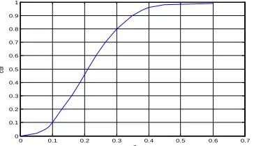
Similarly, in the above test site, the position of target node can be estimated by using the UWB mixed positioning method on the basis of pattern matching. Compare the estimated position and the actual position of reference node to figure out the corresponding error and draw up the accumulation probability distribution function, as is shown in Fig.9.
0 0.1 0.2 0.3 0.4 0.5 0.6 0.7
0 0.1 0.2 0.3 0.4 0.5 0.6 0.7 0.8 0.9 1
m2
cdf
[image:4.612.326.508.362.467.2]Fig.9 Accumulation Probability Distribution Function Of Pattern Matching And TOA Mixed Positioning Error
Fig. 9 shows the accumulation probability distribution function (cdf) of positioning error in UWB mixed positioning on the basis of pattern matching. From Fig. 9, we can see that 95% of positioning error is less than 0.4m2. As a result, this kind of mixed positioning method has high positioning accuracy and it is appropriate for accurate positioning in coal mine.
5. CONCLUSIONS
[image:4.612.102.283.527.646.2]it only needs to lay out the reference node along the wall and the area of reference nodes covers the roadway continuously in an overlapping way.
(2) The pattern matching positioning method will be positioned by two steps. Firstly, coarse positioning makes use of the signal intensity positioning method and the range of intensity value on each reference node; determine the area of target node at the reference node through the signal intensity matching; then the fine positioning makes use of the two reference nodes selected in coarse positioning and UWB TOA ranging to establish the constraint equation to calculate the position of the target nod.
(3) We propose the detection method of arrival moment of DP collected by incoherent energy of UWB signal. This method can detect the arrival moment of DP accurately. This method is easy to implement and makes it possible for positioning of ranging on the basis of arrival moment in underground mines.
(4) Through the test of pattern matching positioning method of area reference node, the error analysis shows this mixed positioning method can reach high accuracy on ranging and positioning.
ACKNOWLEDGEMENT
This work was supported by the National Natural Science Foundation of China (Grant No.s U1261125, 51104157), the Ph.D. Programs Foundation of Ministry of Education of China (Grant No. 20110095120008), the China Postdoctoral Science Foundation (Grant No.20100481181), the Fundamental Research Funds for the Central Universities (Grant No. 2011QNA30), and Jiangsu Overseas Research & Training Program for University Prominent Young & Middle-aged Teachers and Prsesidents.
REFRENCES:
[1] Hamza Soganci , Sinan Gezici , H Vincent Poor. “Accurate positioning in ultra-wideband systems”. IEEE , 2011, 18(2):19-27.
[2] Wu Chunming . “The research of coal mine location technology based on the Ultra-Wideband wireless sensor networks”. IEEE, 2010,3:897-900.
[3] Lei Jiao, Li F Y, Zengyou Xu. “LCRT:A TOA based mobile terminal localization algorithm in
NLOS environment”. IEEE Vehicular
Technology Conference, 2009, VTC Spring
2009, IEEE 69th Vehicular Technology
Conference:1-5.
[4] Qiao Gangzhu, Zeng Jianchao. “Localization algorithm of beacon nodes chain deployment based on coal mine underground wireless sensor network”. Journal of China Coal Society, 2010, 35(7): 1229-1233.
[5] Chin-Der Wann, Hao-Chun Chin. “Hybrid TOA/RSSI wireless location with unconstrained nonlinear optimization for indoor UWB
channels”. 2007 IEEE Wireless
Communications and Networking Conference,
WCNC 2007: 3940-3945.
[6] Yang Wei, Zhou Siyong, Qiao Hua. “Node localization in wireless sensor networks for coal mine security monitoring”. Journal of China
Coal Society, 2007,32(6):652-656.
[7] Liu Zhigao, Li Chunwen, Xing Zhipeng,et al. “Key issues analysis and experiment of the global positioning system in underground tunnel network”. Journal of China Coal Society, 2011, 36(3):519-526.
[8] Zoubir Irahhauten, Giovanni Bellusci, “Gerard J.M,et al. Investigation of UWB ranging in dense indoor multipath environments”. 2006 IEEE Singapore International Conference on
Communication Systems, ICCS 2006:1-5.
[9] Woo Cheol Chung, Dong Sam Ha. “An accurate ultra wideband (UWB) ranging for precision asset location”. IEEE, 2003,389-393.
[10] Markos Losada, Leticia Zamora-Cadenas, Ainara Jim´enez-Irastorza, et al. “Igone V´elez .UWB–based Time–of–Arrival ranging system for multipath indoor environments”. 3rd International Conference on Advances in Circuits, Electronics and Micro-Electronics,
CENICS 2010:17-22
[11] Ismail Guvenc, Zafer Sahinoglu. “Threshold-Based TOA estimation for impulse radio UWB systems”. 2005 IEEE International Conference
on Ultra-Wideband :420-425.
[12] Guvenc I, Chia-chin Chong, Watanabe F. “Joint TOA estimation and localization technique for UWB sensor network applications”. 2007 IEEE
65th Vehicular Technology
Conference,VTC2007-Spring:1574-1578.
[13] Feng Tian, Ying Dong, Enyan Sun, Chuanyun Wang. “Nodes localization algorithm for liner wireless sensor networks in underground coal mine based on RSSI-Similarity degree”. 2011 IEEE 7th International Conference on Wireless Communications, Networking and Mobile
[14] Li Jian, Liu Heping. “A new weighted centroid localization algorithm in coal mine wireless sensor networks”. 2011 IEEE 3rd International
Conference on Computer Research and
Development ,2011,3:106-109.
[15] Venkatesh S, Buehrer R M. “Non-line-of-sight identification in ultra-wideband systems based
on received signal statistics”. IET Microwaves,