Design Calculation and Performance Analysis of Single
Suction Centrifugal Pump
Aye Thida San*, Min Min Oo**, Chaw Wint Yee Zaw**
* Department of Mechanical Engineering, Technological University (Pathein), Myanmar ** Department of Mechanical Engineering, Technological University (Pathein), Myanmar
**Department of Mechanical Engineering, Technological University (Thanlyin), Myanmar
DOI: 10.29322/IJSRP.9.08.2019.p9298 http://dx.doi.org/10.29322/IJSRP.9.08.2019.p9298
Abstract- Centrifugal pumps are used widely for hydraulic transportation of liquids through pipelines where the requirement of head and discharge are moderate. This paper presents the design of impeller and casing of single suction centrifugal pump and performance analysis of losses. The impeller and the casing are a rotating component and a stationary component. Water enters axial flow through the impeller eyes and exits radial flow in centrifugal pump. The pump casing is to control the liquid to the impeller, transfers into pressure the high velocity kinetic energy of the flow from the impeller discharge and leaves liquid away of the energy having imparted to the liquid comes from the volute casing. The design calculation and performance analysis of single suction centrifugal pump are describe because it is the most essential useful mechanical dynamic machine in fluid works which used for water supply plants, irrigation, industry, steam power plants, hydraulic power service, mine and river water pumping system,
In this paper, pump is single stage single suction centrifugal pump and it has a head of 50 m, the flow rate of 200 m3 /hr and the motor speed is 1480 rpm. The value of specific speed is 18.46. The number of blades is 6 blades. The pump power is 29.98KW electric motor and the design is Berman Method is used. The performance analysis of centrifugal pump is carried out the dimensions of centrifugal pump. So shock losses, impeller friction losses, volute friction losses of centrifugal pump are determine in performance analysis of centrifugal pump.
Index Terms- impeller, centrifugal pump design, performance, Berman Method, Euler’s Equation
I. INTRODUCTION
he centrifugal pump is a mechanical device which transports water from a lower level to higher level or from a lower pressure area to a higher pressure area. Mechanical energy is given to the pump and it converts into hydraulic energy of fluid. It consist an impeller rotating within a pump casing. In dynamics pump, the energy is transferred by rotary motion is dynamic action. The input power of the pump is mechanical energy of the drive shaft and the output power is hydraulic energy. The rotating blade system imparts a force on the fluid, thereby making the fluid to move. The fluid coming into the pump is pushed towards the outlet mechanically where positive pressure is generated. Pumps are classified in number of the ways based on their purpose, specifications, design and environment.
In a centrifugal pump, the liquid forces by atmospheric and other pressure into a set of rotating vanes. A centrifugal pump consists of a set of rotating vanes enclosed within a housing or casing that is used to impart energy to a fluid through centrifugal force.
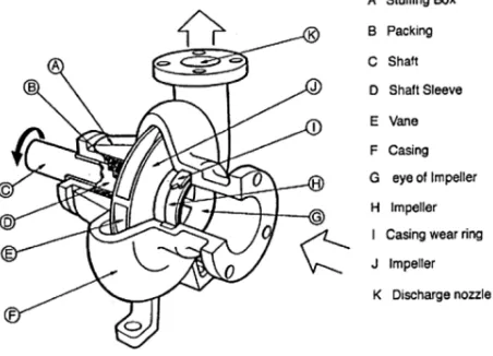
[image:1.612.341.567.373.536.2]A pump transfer mechanical energy from some external source to the liquid flowing through it and losses occur in any energy conversion process. The energy transferred is predicted by the Euler equation. The energy transfer quantities are losses between fluid power and mechanical power of the impeller or runner.
Figure 1: Single Suction centrifugal Pump
II. DESIGN CALCULATION AND PERFORMANCE ANALYSIS OF SINGLE SUCTION CENTRIFUGAL PUMP
A. Design of Centrifugal pump
The design pump is single stage centrifugal pump. Impeller is designed on the basic of design flow rate, pump head and pump specific speed. So, the design data are required to design the centrifugal pump. For design calculation, the design parameters are taken as follows:
Flow rate, Q = 200 m3/hr
Head, H = 10 m Rotational speed, N = 1480 rpm
Density of water, ρ = 1000 kg/m3
Inlet impeller diameter, D1 =110 mm
Outlet impeller diameter, D2 = 310 mm
Impeller width at inlet, b1 =40 mm
Impeller width at outlet, b2 =25 mm
Overall efficiency, η0 = 90 %
Suction pipe diameter = 6 inch Discharge pipe diameter = 3 inch
The design of centrifugal pump incluses a large number of inters dependent variables so there are several possible designs for the same duty. One of the most difficult design problems is to predict the impeller head slip. The difference between the theoretical head for a number of impeller vanes and the theoretical head deduced from the net horse power given to the fluid passing through the impeller. Before pump design or selection can be got, specification is needed to be established which express several requirements.
Specific speed is used to classify impeller on the basic o f their performance, and proportions regardless of their actual size or the speed at which they operate.
Specific speed; ns =
4 3
H
Q
3.65N
(1)Where, ns = specific speed Q = flow rate N= rotational speed H = head
Capacity, volute flow rate of a pump is the amount of water pumped per unit time and it is also known traditionally as volume flow rate. The capacity is directly related with the velocity of flow in the suction pipe.
Capacity;
Q
=
AV
(2) Where, A = area of pipeV = volume flow rate
Water power and shaft power
The water power is the power imported to the water by the pump. To calculate the water power, the flow rate and the pump head must be known. As a result, to provide a certain amount of power to the water a large amount of power must be provided to the pump shaft. The power is called brake power. The efficiency of the pump determines how much more power is required at the shaft.
The water power is determine from the relationship
ρgHQ
N
=
(3) Where, ρ = density of waterg = gravitational acceleration
The shaft power is;
0
η
waterpower
power
shaft
=
(4)Where, η0 = overall efficiency
Pump efficiency is
r v m
0
η
η
η
η
=
×
×
(5)Where, ηm = mechanical efficiency
ηr =hydraulic efficiency
ηv= volumetric efficiency
The inlet area of a impeller is;
1
D
124
π
A
=
(6)Where, D1 = inlet impeller diameter
The outlet area of a impeller is;
A
2=
πD
2b
2 (7)Where, D2 = outlet impeller diameter
b2 = impeller width at outlet
Velocity diagram
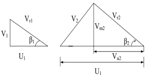
[image:2.612.313.570.435.568.2]A study of the several component velocities of flow through an impeller is best carried out graphically by mean of velocity vectors. The shape of such vector diagram is triangular and they are called velocity triangles. It can be drawn for any point of the flow path through the impeller, but usually attention is focused on the inlet and outlet triangles.
Figure 2: Inlet Flow Velocity and Outlet Flow Velocity Diagram
The blade velocity at inlet is;
60
N
πD
U
1=
1 (8)Where, U1 = blade velocity
N = rotational speed
1 1 f1
b
πD
Q
V
=
(9)Where, Vf1 = radial velocity at inlet
b1 = impeller width at inlet
The blade angle at inlet is;
1 1 f1 1
V
U
V
tan
β
ω−
=
(10)Where, Vω1 = tangential velocity
β1 = blade angle at inlet
The blade velocity at outlet is;
60
N
πD
U
22
=
(11)Where; U2 = tangential blade velocity
The relative velocity at outlet is;
2 2 f2
b
πD
Q
V
=
(12)Where, Vf2 = radial velocity at outlet
b2 = impeller width at outlet
the blade angle at outlet is;
ω2
f2 2
V
V
tan
α
=
(13)Where; α2 = guide vane angle at outlet
Vω2 = tangential velocity at outlet
ω2 2 f2 2
V
U
V
tan
β
−
=
(14)Where; Vω2 = tangential velocity at outlet
β2 = blade angle at outlet
Theoretical head is;
ω2
2
th
U
V
g
1
H
=
(15)
Where; H t h = theoretical head
Blade number
Higher frication losses are related to many blade casing low blade loading. The choice of fewer blades leading to a higher blade loading hydraulic losses may rise due to increasing secondary flow and stronger deviating between blade and flow direction.
2
β
β
sin
D
D
D
D
k
Z
1 21 2 1 2
+
−
+
≈
(16)III. PERFORMANCE ANALYSIS OF SINGLE SUCTION CENTRIFUGAL PUMP
Net Theoretical Head
If the slip factor is known, the net theoretical head may be obtained from Euler’s head. By using Euler’s equation, It is possible to relate the theoretical characteristic obtained to the actual characteristic for various losses responsible for the difference. The slip factor is used which various with flow rate, enables the net theoretical head curve to obtained. At flow rate below design flow rate, separation occurs on the suction side of the blade.
The net theoretical head is calculated by;
g
V
U
H
thn=
2 ω2 (17)At the outlet, the whirl velocity is ;
V
ω2=
U
2σ
−
V
ω2cot
β
2 (18)Where, ϭ = slip factor
(
)
0.7 1 0.5 2Z
β
sin
β
1
σ
=
−
(19)Shock Losses
The shock loss is considered major losses at the impeller inlet caused by the mismatch of fluid and metal angles. Shock losses are finding everywhere in the flow range of the pump. Shock loss is given by following equation;
2 N s
s
k(Q
Q
)
h
=
−
(20) Maximum flow rate;ω1
1 1
N
πD
b
V
Q
=
(21) The shut off head;2g
U
U
H
2 1 2 2 off shut−
=
− (22)
The hydraulic efficiency is;
(
)
21 r
0.172
logD
0.42
1
η
−
−
=
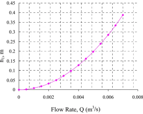
(23) [image:4.612.40.275.217.398.2]The flow rate and the shock loss of head is showed in Figure 3. The shock loss of head is increasing when the flow rate is decreasing. Shock loss is not in the design point condition. If this condition is over, the value of the shock loss of head is high.
Figure 3 Shock Losses and Flow Rate Graph
Impeller Friction losses
The impeller was designed that the width of the impeller would become small and friction loss at the flow passage would become large. Therefore to relive the increase in friction losses, radial flow passage on the plane of the impeller was adopted. The friction losses can be found for energy dissipation due to contact of the fluid with solid boundaries such as stationary vanes, impeller, casing, disk and diffuser.
The impeller friction losses are;
(
)(
)
4g
H
2sin
β
V
V
D
D
b
h
r 2
2 r2 r1 1 2 2 1
−
−
=
(24)The hydraulic radius;
2 2 2
2 2 2
r
sin
β
Z
πD
b
sin
β
Z
πD
b
H
+
=
(25)The inlet relative velocity is;
1
ω1
r1
sin
β
V
V
=
(26)The outlet relative velocity;
2
ω2
r2
sin
β
V
V
=
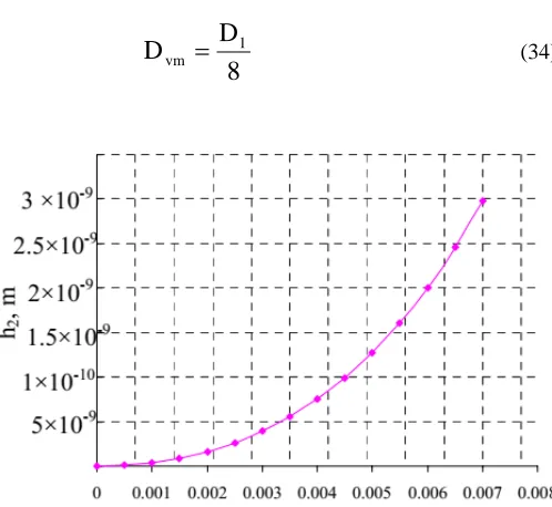
(27)In figure 4 is showed the influence of the geometry of the impeller friction losses. The analysis of the curves descries that small difference between the points for the flow rate and the impeller friction loss of head. The impeller loss of head is increasing when the flow rate is increasing.
Figure 4 Impeller Friction Losses and Flow Rate Graph
The losses of Volute Friction
The losses of volute friction results from a mismatch of the velocity is outer the impeller and the velocity in the volute throat. If the velocity reaching the volute throat is larger than the velocity at the throat, the velocity head difference is less. The velocity reaching the volute throat by assuming that the velocity is leaving the impeller decreases in proportional to the radius because of the conservation of angular momentum.
The volute friction loss are;
2g
V
C
h
2 3 v
2
=
(28)The volute throat velocity is;
3 3
A
Q
[image:4.612.323.572.273.473.2]The volute throat area;
=
3 2 u2 3
D
D
V
A
(30)Whirl velocity;
2
ω2
2
u2
U
V
cot
β
V
=
−
(31)The volute flow coefficient is;
×
+
=
vm vm v
D
L
0.02
1
C
(32)The volute circumferential length;
8
πD
L
vm=
1 (33)The diameter of volute is get tangent circle from the geometry of volute casing.
The volute mean diameter is;
8
D
D
1vm
=
(34)
Figure 5 Volute Friction Losses and Flow Rate Graph
The volute losses and flow rate graph are figure 5. When the flow rate is increased, the volute friction loss of head increases. The volute friction coefficient is decrease for small values of the volute flow coefficient.
[image:5.612.45.294.362.591.2]IV. DESIGN RESULTS OF CENTRIFUGAL PUMP
Table I: calculation Result of single suction centrifugal pump
No Descriptions Symbol Results 1 Guide Vane angle at inlet α 1 0
2 Guide Vane angle at outlet α 2 6.23˚
3 Blade angle at inlet β 1 24.98˚
4 Blade angle at outlet β 2 32˚
5 Number of blades Z 6
6 Inlet area of impeller A 1 0.0863 m2
7 Outlet area of impeller A 2 0.0243 m2
8 Specific Speed ns 18.46
9 Water power 20.12Hp
10 Shaft power 29.98 KW
V. CONCLUSION
Centrifugal pump are fluid kinetic machines designed for increasing power within a rotating impeller. In centrifugal pumps, the delivery head is depended on the flow rate. This relationship, are called pump performance, is illustrated by curves. Characteristic curve of a centrifugal pump value is getting of theoretical head, slip, shock losses, impeller losses and volute losses are calculated by varying volume flow rate. The performance analysis of centrifugal pump is predicted in this paper.
A centrifugal pump is using a rotating impeller to increase the pressure and flow rate of a fluid. The fluid is entering the pump impeller along to the rotating axis and is accelerating by the impeller, flowing radial outwards into a diffuser or volute chamber, from where it exits into the downstream piping system. The angle value of inlet and outlet blade angel degree are large the pump pressure is fall down. The impeller is very important in pump because that can be change many performance of a fluid work.
ACKNOWLEDGMENT
The author likes to express her special thanks to Dr. Aye Aye Thin, Professor, Department of Mechanical Engineering Technological University (Pathein). The author is mentioning all of her teachers and parents who taught her everything from childhood until now, and her colleagues for their encouragement, helpful suggestion, true-line guidance, supervision this paper.
REFERENCES
[2] Igor, J, Joseph. P,and Charles, C.2001. Pump Hand Book.USA. McGraw-Hill Company
[3] Khin Maung Aye, U.December.2000. Fluid Machinery of Mechanical Engineering
[4] Lexicon, Centrifugal Pump,1975 .
[5] Sam Yedidiah, No Date, Centrifugal pump User’s Guide Book. An international Thomson Publishing.
[6] Igor J.Karassik,Joseph P.Messina, Paul Cooper, Charles C.Head, Pump Handbook 4th Edition,dec2007.
[7] Daugherty, L.1915. Centrifugal Pumps. McGraw-Hill Book Company.Fnc. [8] Frank, A.1953. Pumps. 2nd Edition.Mc Graw-Hill.
[9] Karassik, and Roy Carter, J.1960. Centrifugal Pump Selection, Operating and Maintenance. McGraw- Hill Book Company.
[10] John Tuzson, Centrifugal Pump Design 1st Edition,Sep 2000
[11] Johann Friedrich Gulich,Centrifugal Pumps 3rd Edition,2014
[12] Zoeb Hussain,Mohd.Zulkifly Abdullah, ZanialAlimuddin, Basic Fluid Mechanics and Hydraulic Machines,Feb 2009
[13] Khin Cho Thin, Mya Mya Khaing, and Khin Maung Aye, Design and Performance Analysis of Centrifugal Pump
[14] Cho Cho Khaing, Nyi Nyi, Design of Single Suction Centrifugal Pump and Performance Analysis by Varying the speed of impeller
First Author – Aye Thida San, M.E (Mech), Technological University (Pathein) and [email protected] Second Author – Min Min Oo, M.E (Mech), Technological University (Pathein) and [email protected] Third Author – Chaw Wint Yee Zaw, M.E (Mech),