Automation of Material Handling with Bucket Elevator
and Belt Conveyor
Ghazi Abu Taher
1, Yousuf Howlader
2, Md. Asheke Rabbi
3, Fahim Ahmed Touqir
41,2,3,4 Department of Industrial Engineering and Management 1,2,3,4 Khulna University of Engineering & Technology
Abstract-Belt conveyor & Bucket elevator are the media of transportation of material from one location to another in a commercial space. Belt conveyor has huge load carrying capacity, large covering area simplified design, easy maintenance and high reliability of operation. Belt Conveyor system is also used in material transport in foundry shop like supply and distribution of molding sa nd, molds and removal of waste. On the other hand Bucket elevator can be of great use during bulk material handling. This paper is mainly based on the combination of Belt & Bucket Conveyers to perform complex task within a short time and successfully in a cost effective way. On account of this, a machine and its physical description is covered here with some basic calculation.
Index Term- Belt Conveyor, Bucket Elevator, Weight sensor, Bulk material. I.
I
NTRODUCTIONI
nitialstage is to form a pre project plan. During the project design stage for the transport of raw materials or finished products, the choice of the method must favor the most cost effective solution for the volume of material moved; the plant and its maintenance; its flexibility for adaptation and its ability to carry a variety of loads and even be overloaded at times. Again a rough sketch of the proposed machine is evaluated so that the basic parts can be easily understood. More importantly a development team was formed to monitor the design to be robust and accelerate the work.II. WHY THIS MACHINE
The conveyor belt changed the face of the industrial economy around the world. Today, it has applicable uses in countless industries, such as transportation and food services. A bucket elevator or conveyer is a mechanism for hauling flow able bulk materials by following an assembly line in horizontal, vertical or inclined direction. According to the survey performed 85% industrial units face difficulties in handling bulk material packaging. The difficulties mainly arises when it is necessary to convey a bulk material through a linear distance as well as a certain height. Conventional ways are responsible for material wasting, time wasting & above all a poor management. In order to overcome those draw backs not only Belt & Bucket conveyers are combined but also artificial intelligence brought in use. Efficiency & accuracy of the system were ensured using the sensor.
III. PROJECT PLANNING
Our project is based on the handling of bulk material and its packaging process. It is a combination of bucket elevator and belt conveyor and the packaging process is controlled automatically by using microcontroller. A weight sensor is attached with the microcontroller which helps to package the bulk material at proper amount.
Figure1: Primary sketch of the machine. III.A. BUCKET ELEVATORS
A bucket elevator consists of a series of uniformly fed buckets mounted on an endless chain or belt which operates over head and foot wheels. The buckets are used to elevate (usually vertically) pulverized, granular, or lumpy materials. The material is received at the boot, raised and then discharged by passing over the head wheel at the top, into a discharge chute. Generally this mechanism is enclosed in a casing, especially the head and foot sections. Some elevators are self-supporting, but more often they are supported by, or at least braced against a structural steel frame. Inclined elevators, which are seldom enclosed, are popular for handling
.
Which type of bucket and bucket elevator was selected?
An inclined twin chain bucket elevator was selected for this project. The angle of inclination was 45° from the vertical. And the selected bucket was Deep type bucket. The front edge of buckets is sheared off at an angle of 65 making them deep.
Charge and Discharge of Buckets: (Scooping charge and centrifugal discharge)
The material is either scooped up by the buckets in the elevator boot or is fed directly into the buckets. Here bulk material, cement, sand, saw dust, crushed coal, sugar, rice, wheat will be conveyed. So, spaced buckets of belt-and-chain elevator was selected which works on the principle of scooping material.
Centrifugal discharge type bucket elevator was selected. In centrifugal-discharge bucket elevators, the material to be elevated is dug out of the boot and discharged by centrifugal force developed when the bucket is taken around the head pulley (or sprocket) and falls directly into the discharge spout of the upper casing. Before reaching the pulley, the buckets moves uniformly along a rectangular path and only the force of gravity acts on the load; when the bucket begins to turn around the pulley (or sprocket), the centrifugal force
is added to the gravity. In the above equation
Mass of the load contained on the bucket;
Speed of the center of gravity of the load in the bucket, m/sec;
Radius of rotation, mm;
Acceleration of the force of gravity, m/sec2
The resultant of these two forces changes its magnitude and direction as the bucket turns. The particle ejected from the bucket follows a parabola within the upper part of the elevator casing and falls on the chute of the discharge spout.
III.B. BELT CONVEYOR
A conveyor belt (or belt conveyor) consists of two or more pulleys, with a continuous loop of material - the conveyor belt - that rotates about them. One or both of the pulleys are powered, moving the belt and the material on the belt forward. The powered pulley is called the drive pulley while the unpowered pulley is called the idler. There are two main industrial classes of belt conveyors; Those in general material handling such as those moving boxes along inside a factory and bulk material handling such as those used to transport industrial and agricultural materials, such as grain, coal, ores, fines and lumps material. Conveyors are durable and reliable components used in automated distribution and warehousing. In combination with computer controlled pallet handling equipment this allows for more efficient retail, wholesale, and manufacturing distribution. It is considered a labor saving system that allows large volumes to move rapidly through a process, allowing companies to ship or receive higher volumes with smaller storage space and with less labor expense.
III.C. ELECTRONIC COMPONENTS
1.
Weight sensor:Figure 2: Pictorial view of weight sensor
2.
Specifications:
Capacity g 500g
Output sensitivity mv/v 0.5±0.1
Nonlinearity %.F.S 0.05
Hysteresis %F.S 0.05
Repeatability %F.S 0.05
Creep(30min) %.F.S 0.05
Temperature effect on sensitivity %F.S/10℃ 0.05
Temperature effect on zero %F.S/10℃ 0.05
Zero balance %F.S ±0.5
Input resistance Ω(ohms) 1120±10
Output resistance Ω(ohms) 1000±10
Insulation resistance MΩ(ohms) ≥2000
Recommended excitation voltage v 5v
Method of connecting wire red: Exc + black: Exc – green: Sig + white:Sig -
Dimension(mm): 45 x 9 x 63.
Hardware install:Weight sensor output 0V when the load less than 150g, so we cannot directly measure the load. My method is using a 200g local avoid measure blind spot .We read the analog data of 200g weight as no-load(0g),read the analog data of 700g weight as full load(500g).
Figure 3: Circuit diagram of Weight Sensor
[image:3.612.66.555.480.635.2]IV. WORKING PROCEDURE
Some sequential steps are adopted while building up this machine. Some machining process (such as metal cutting, soldering, welding, facing, turning, grinding, boring and drilling) were identified and incorporated to construct the parts. The main purpose of our working procedure was to build up a functional prototype.
[image:4.612.38.288.51.178.2]IV.A. MACHINE COMPONENTS The main components of our machine are given below-
Table I – Parts of our machine.
Bucket Elevator Belt Conveyor Electronic components
Casing Belts Weight sensor Buckets Idlers Microcontroller Chains Centering device 24 volt dc motor Sprockets Drive units Adapter
Take-ups Take-ups Capacitor Boot section Bending the belt Register Drive units Loading and discharging device Circuit board Elevator Frame Belt cleaner
Conveyor Frame
IV. B. MACHINING PROCESSES
The various machining processes those were used in making The Bucket Conveyor and The Belt Conveyor are described below:
1.
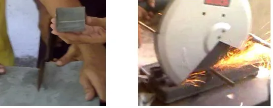
Metal Cutting:Various metal cutting tools were used here such as-
i
Sniping tool: To cut the thin metal sheet to form the shape of bucketii
Hack Saw: To cut the shaft into desired length.iii
Grinder cutting: To cut the thick metal bar into required length for making frame. [image:4.612.169.446.572.682.2]
Figure 4: Cutting Sheet metal with sniping tool (left), shaft with Grinding Cutter (right).
The buckets were made from thin metal sheet. So in spite of welding soldering was used to join the outer edges of the bucket to make the bucket strong enough during operation.
Figure 5: Soldering buckets.
3.
Welding:In this process welding was widely used. As the project was to make a small prototype and there was a small budget for it, welding was used here for most of the joining process. Welding was used to:
i
Attach the sprocket to the shaft.ii
Attach the bearing to the shaft.iii
Hold the bearing in the bearing holder.iv
Attach the bearing holder to the frame.v
Form the frame of both bucket and belt conveyor.vi
Join the bucket conveyor’s driving shaft and belt conveyor’s driving shaft to the electric motors. [image:5.612.224.404.337.449.2]vii
And to join many other parts to the frame.Figure 6: Welding process.
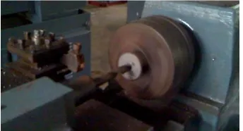
4.
Boring:The sprocket was bought from the market. As the hole of the sprockets was smaller than the outer diameter of the shaft, these holes were enlarged by boring method with the help of lathe machine.
Figure 7: Boring with Lathe Machine.
5.
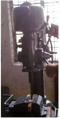
Drilling:Drilling process was also used here for different purposes such as:
i
The shaft of the pulley of the belt conveyor on loading portion is stationary while the pulley is rotatable with the help of bearing. This shaft is held by two metal bars and these bars were drilled to hold the shaft.ii
In this project two wooden pulleys were used. Both these pulleys were drilled along its central axis to make a path of shaft. [image:5.612.221.393.501.594.2]Figure 8: Drilling operation.
6.
Grinding: [image:6.612.118.494.505.606.2]It has been already mentioned that the welding process was widely used here. So, grinding process was also used here to grind the various parts after cutting to get a plane surface for welding. The welded parts were also grinded for fine surface.
Figure 9: Grinding operation.
7.
Facing and Turning:Turning process was adopted for two purposes:
i
To match the outer diameter of the shaft to the inner diameter of the bearing.ii
To convert rectangular wooden bar into cylindrical pulley.And where there is used turning process there is also used facing process for centering in the lathe machine.
Figure 10: Facing operation (left), turning operation (right) with Lathe Machine. V. PARTS OF MACHINE
Brief description of Automation of Material Handling with Bucket Elevator and Belt Conveyor is given below: V.A. PARTS OF BUCKET ELEVATOR
The elevator is usually enclosed in a steel casing, to provide a means of support and as a matter of safety and dust retention. A casing can be made dust-tight, either by using a sealing medium, or continuously welding the comer angles to the plate. The upper casing of the elevator contains manholes providing access for inspections and repairs. As it was a small project work casing was avoided here.
2.
Buckets:It is the essential part of this conveyor. It carries the bulk material to the required place. It was made with a 5mm thin pl ain steel sheet by folding the sheet at a certain dimension.
[image:7.612.69.532.147.344.2]Formation of bucket:
Figure 11: Sequential stages of bucket formation.
3.
Chains: [image:7.612.228.382.418.519.2]A chain serves as a pulling member of bucket elevators. The buckets were attached to two chains bolted to the rear of buckets. The power of the sprockets transmits through the chains. It also helps to pull up the bucket with full of bulk materials.
Figure 12: Chains.
4.
Sprockets:It serves as driving unit. It holds the chains of the conveyor which hold the bucket. With the help of sprockets the power of motor is transmitted from one side to the other side of the conveyor. The number of teeth of the sprocket was 32. The sprockets were attached to the shafts rigidly and the shafts were attached to the frame with the help of bearings and bearing holders.
Figure 12: Sprocket with shaft.
5.
Take-ups:[image:7.612.236.378.588.694.2]
Normally, elevators have the screw-type take-up on the foot or boot shaft unless space does not permit. If it is necessary to place the screw-type take-up on head shaft, the centers of the bucket elevator should not exceed 90 feet, because the total weight of chain (or belt) plus buckets and load in buckets on up or carry side, is hanging on the take-up screw in tension. Wherever a head take-up is used, the next larger sized head shaft from that recommended should be used, as the vibration is transferred to the head shaft through the pickup in the boot. Gravity take-ups are used on many elevators, particularly on powdery or aerated material such as cement, lime, and gypsum. A softening effect is encountered at the pickup which must be absorbed by this floating take- up. The frame supporting the shaft and wheel simply rides up and down in angle or channel guides, attached to the inside of the casing. This mechanism was also avoided here.
6.
Boot Section:The elevator boot holds the feed hopper. When moist slow-flowing materials are transported, the hopper is located comparatively high and its bottom is inclined at an angle of 60 ; it is located at a low height and its bottom is inclined by 45 when dry free-flowing materials are handled. The side walls of the lower casing contain covered manholes for maintenance and repair.
7.
Drive units:In the bucket elevator motive power is transmitted to the elevator by friction as it wraps around the driving shaft rotated by an electric motor. A 24 volt dc motor is used to run this elevator. The drive comprises the following parts: two sprockets, motor.
V.B. PARTS OF BELT CONVEYOR
1.
Belts:Camel hair, cotton (woven and sewed), duck cotton and also rubberized textile belts of various types are employed in belt conveyors. Our project was to build a prototype of belt conveyor. So we used a piece of raxine and it is connected by sewing with sewing machine.
Figure 13: Polymer Belt.
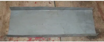
2.
Idlers: [image:8.612.206.406.524.606.2]Generally the belt is supported by idler rollers, in rear cases by solid wood or sheet steal runway or a combination support comprising sections of a runway with idler rollers. According to their location on the conveyor, idlers are classified as upper (supporting the loaded strand on the belt) and lower (supporting the idle return strand of the belt). In our project we used steal sheet instead of idlers. These are used mainly in conveyors handling bulk loads, less frequently unit loads etc.
Figure 14: Sheet metal idler.
3.
Centering device:Figure 15: Centering device
4.
Drive units:In the belt conveyor motive power is transmitted to the belt by friction as it wraps around the driving pulley rotated by an electric motor. A 24 volt dc motor is used to run this conveyor. The drive comprises the following parts: two pulleys, motor and the transmission gear between the motor and the pulley. For inclined conveyors a breaking device is included which prevents slipping back of the loaded belt under the weight of material. Ours is a horizontal conveyor that’s why we don’t need to use the breaking device.
5.
Take ups:A belt conveyor may have screw or counterweighted take up. The latter may in turn be divided into horizontal and vertical type. In our conveyor we don’t use take up system. We simply connect the belt with the pulleys which rotates by the motor.
6.
Bending the belt:The belt is bent by means of terminal or intermediate turning pulleys. We use two wooden pulleys, one is in the loading side and another one in the discharging side that is connected by the motor.
7.
Loading and discharging device:The design of loading devices depends on the nature and characteristics of the load conveyed and the method of loading. Our conveyor is made to convey the bulk material which is loaded by the bucket conveyor into the hopper which is called the feed hopper that helps to load the material into belt at the proper position. The discharge for the bulk materials used a discharge plough board placed at a certain angle 310 to the longitudinal axis of the belt and fastened on the frame. This is installed slightly inclined section 100 of the conveyor.
Figure 16: Discharged material holder.
8.
Belt cleaners:Wipers or scrapers serve to clean the outer belt surface of dry particles cleaning to it. For wet and sticky material revolving brushes are used. Our conveyor conveys dry bulk material so we use a wiper just below the discharge plough board.
9.
Conveyor frame: [image:9.612.247.365.576.654.2]The supporting structure of the conveyor intermediate section is usually electric welded of profiled rolled stock, angle iron or channel bar, and consists of longitudinal beams, uprights and cross-pieces. The height of the frame is usually 7”, the spacing between the uprights is 4” to 5”.
Figure 17: Conveyor frame.
VI. CALCULATION
The handling capacity of a bucket elevator, Q tons per hour is
Q = 3.6*v*ϒ*Ψ (io /a)
=3.6*0.6*1.5*0.85*8 =22 tons per hour
Where,
io= capacity of the bucket a= bucket spacing in meter
v= chain speed, m/sec
ϒ= bulk weight of the load, tons / m3 (dry sand)
Ψ= bucket loading efficiency
The maximum static tension of the driving member Smax is
Smax 1.15H (q+K1qo)
1.15*1 (10.19+ 1.5* 26.4) 171.76 Kg
Where,
H= height to which the load is elevated, m
q= weight of the load per meter of elevator length, (kg/m) = Q/ 3.6v qo= weight per meter of chain with bucket, (kg/m) K2Q
K1, K2, K3= factor allowing for the resistance to motion and bending of the driving member and the buckets Required motor power on the drive shaft ( not including losses in the driving gear), No is
No (QH/367)*(1.15+K2K3v) W = 375 W
VI.B. CALCULATION OF BELT CONVEYOR
The basics of the Calculations of Conveyor Belt Design Parameters: Input data:
Conveyor capacity (Cc) = 1500 t/h = 416.67 Kg/sec Belt speed (V) = 1.5 m/sec
Conveyor height (H) = 20 m Conveyor length (L) = 250 m Mass of a set of idlers (mi) = 20 Kg Idler spacing (l) = 1.2 m
Load due to belt (mb) = 25 Kg/m Inclination angle of the conveyor (δ) = 5 0
Coefficient of friction (f) = 0.02 Start-up factor (Ks) = 1.5 Drive efficiency (Kd) = 0.9 Friction factor (Cr) = 15
Breaking strength loss factor (Cv) = 0.75
Load due to idlers (mi): This can be calculated as below:
mi = (mass of a set of idlers) / (idlers spacing)
mi = (20/1.2) = 16.67 Kg/m
Belt tension: The belt of the conveyor always experience a tensile load due to the rotation of the electric drive, weight of the conveyed materials, and due to the idlers. The belt tension at steady state can be calculated as:
Tb = 1.37*f*L*g*[2*mi+ (2*mb + mm)*cos (δ)] + (H*g*mm)
Belt tension while starting the system: Initially during the start of the conveyor system, the tension in the belt will be much higher than the tension in steady state. The belt tension while starting can be calculated as:
Tbs =Tb*Ks
Tbs = 1.5 * 77556.88 = 116335.32 N
Where, Tbs is in N.
Tb = the steady state belt tension in N.
Ks = the start-up factor
Power at drive pulley: The power required at the drive pulley can be calculated from the belt tension value as below:
Pp = (Tb*V)/1000
Pp = (77556.88*1.5)/ 1000 = 116.335 Kw
Where, Pp is in KW.
Tb = steady state belt tension in N. v = belt speed in m/sec.
Sizing of the motor: The minimum motor power can be calculated as:
Pm = Pp/Kd
Pm = 116.35/0.9 = 129.261 Kw
Where, Pm is in Kw.
Pp = the power at drive pulley in Kw Kd = Drive efficiency.
Acceleration : The acceleration of the conveyor belt can be calculated as:
A= (Tbs – Tb)/ [L*(2*mi + 2*mb+mm)]
A = (116335.32 - 77556.88)/ [250*{(2*16.67) + (2*25) + (416.67/1.5)}] = 0.429 m/sec2
Where, A is in m/sec2
Tbs = the belt tension while starting in N.
Tb = the belt tension in steady state in N.
L = the length of the conveyor in meters.
mi = Load due to the idlers in Kg/m. mb = Load due to belt in Kg/m.
mm = Load due to the conveyed materials in Kg/m.
Belt breaking strength: This parameter decides the selection of the conveyor belt. The belt breaking strength can be calculated as:
Bs= (Cr*Pp)/ (Cv*V)
Bs = (15*116.35) / (0.75*1.5) = 1551.33 N/mm
Where,
Bs is in Newton. Cr = friction factor
Cv = Breaking strength loss factor Pp = Power at drive pulley in Newton. V = belt speed in m/sec.
The bucket elevator and belt conveyor calculations methodology discussed in the article is to be used only for the guidance on calculating the initial conveyor design parameters; the final design must be validated by using the similar tools before building the prototype.
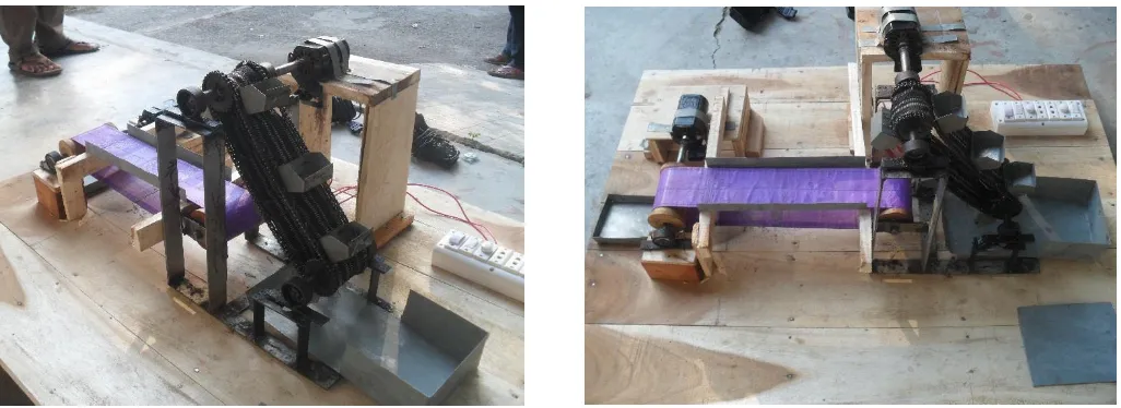
VII. SYNCHRONIZATION OF BUCKET ELEVATOR AND BELT CONVEYOR The final out-look of the machine after synchronizing the Bucket Elevator and Belt Conveyor:
[image:12.612.53.566.146.333.2]
Figure 18: Synchronization of bucket elevator and belt conveyor. VIII. CONCLUSION
The main purpose for building this machine is to automate the handling of bulk material and its packaging. We are trying to build a prototype for expressing our motive on this project. Though we have some mistakes caused by human error but we believe that we can clear our concept by our work. The total process is controlled by a control system automatically. We mainly focus on the packaging system. The control system helps to package the right amount of material in several packet. It stops the machine for a certain time between two packaging process. So once it is set the requirement of skilled operator is also reduced as compared to a manual system.
ACKNOWLEDGMENT
Hundreds of people contributed for making this product in large and small ways. We are grateful to the many industrial practitioners and customers who provided data, examples and insights. We appreciate the assistance we have received from numerous academic friends, research assistants and support staff from our sponsors. Indeed we could not have completed this project without the cooperation and collaboration of our honorable teachers. Thank you all.
REFERENCES
[1] A. Spivakovshy and V.Dyachkov, “Conveyors and related Equipment”, Chapter-IV, VII & XI, Peach Publishers, MOSCOW.
[2] Wong, M. M., C. H. Tan, J. B. Zhang, L. Q. Zhuang, Y. Z. Zhao and M. Luo,. 2006;On-line reconfiguration to enhance the routing flexibility of complex automated material handling operations, Robotics and Computer-Integrated Manufacturing, March 2006.
[3] Babiceanu, R. F., Chen. F. F. and R.H. Sturges. 2005; “Real-time holonic scheduling of material handling operations in a dynamic manufacturing environment” Robotics and Computer-Integrated Manufacturing, Volume 21, Issues 4-5, August-October 2005.
AUTHORS
First Author – Ghazi Abu Taher, 3rd year student, BSc, Department of Industrial Engineering & Management, Khulna University of
Engineering & Technology (KUET), Khulna-9203, Bangladesh. Email - ghaziabutaher@yahoo.com
Second Author – Yousuf Howlader, 3rd year student, BSc, Department of Industrial Engineering & Management, Khulna University
of Engineering & Technology (KUET), Khulna-9203, Bangladesh. Email - shaonys046@gmail.com
Third Author – Md. Asheke Rabbi, 3rd year student, BSc, Department of Industrial Engineering & Management, Khulna University
Forth Author – Fahim Ahmed Touqir, 3rd year student, BSc, Department of Industrial Engineering & Management, Khulna