International Journal of Emerging Technology and Advanced Engineering
Website: www.ijetae.com
(ISSN 2250-2459, ISO 9001:2008 Certified Journal,
Volume 7, Issue 5, May 2017)
65
Optimization of the Control Performance for Renewable Energy
Generators in the Remote Area
Wadah Aljasim
1,
Alaa Ibrahim
2,
Walaa Hussein
3,
Reham Abdulwahab
41Head of Research’s Department & IUC, Sydney, Australia 2,3,4Researcher of Iraq University Collage & IUC, Basra, Iraq
Abstract— This paper shows the optimization of the control performance for three renewable energy generators (Wind, Solar, batteries bank generators) via PLC producing the required electrical supply for the remote area.
Keywords—Wind, Solar, batteries bank generators, diesel
generator and PLC.
I. INTRODUCTION
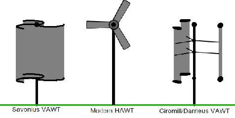
[image:1.612.50.288.509.629.2]Wind turbines can rotate about either a horizontal or a vertical axis, the former being both older and more common [1]. They can also include blades (transparent or not) [2] or be bladeless [3]. Vertical designs produce less power and are less common [4]. Horizontal-axis wind turbines (HAWT) have the main rotor shaft and electrical generator at the top of a tower, and must be pointed into the wind. Small turbines are pointed by a simple wind vane, while large turbines generally use a wind sensor coupled with a servo motor. Most have a gearbox, which turns the slow rotation of the blades into a quicker rotation that is more suitable to drive an electrical generator [5]. Figure 1 shows the three primary types: VAWT Savonius, HAWT towered; VAWT Darrieus as they appear in operation.
Figure 1: Three Primary Wind Generators.
Since a tower produces turbulence behind it, the turbine is usually positioned upwind of its supporting tower. Turbine blades are made stiff to prevent the blades from being pushed into the tower by high winds.
Additionally, the blades are placed a considerable distance in front of the tower and are sometimes tilted forward into the wind a small amount. Downwind machines have been built, despite the problem of turbulence (mast wake), because they don't need an additional mechanism for keeping them in line with the wind, and because in high winds the blades can be allowed to bend which reduces their swept area and thus their wind resistance. Since cyclical (that is repetitive) turbulence may lead to fatigue failures, most HAWTs are of upwind design.
International Journal of Emerging Technology and Advanced Engineering
Website: www.ijetae.com
(ISSN 2250-2459, ISO 9001:2008 Certified Journal,
Volume 7, Issue 5, May 2017)
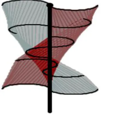
[image:2.612.83.284.290.489.2]One advantage of this arrangement is that the turbine does not need to be pointed into the wind to be effective, which is an advantage on a site where the wind direction is highly variable. It is also an advantage when the turbine is integrated into a building because it is inherently less steerable. Also, the generator and gearbox can be placed near the ground, using a direct drive from the rotor assembly to the ground-based gearbox, improving accessibility for maintenance. However, these designs produce much less energy averaged over time, which is a major drawback [4-8]. Figure 2 shows the vertical axis twisted Savonius type turbine.
Figure 2: A vertical axis Twisted Savonius type turbine
The key disadvantages include the relatively low rotational speed with the consequential higher torque and hence higher cost of the drive train, the inherently lower power coefficient, the 360-degree rotation of the aero foil within the wind flow during each cycle and hence the highly dynamic loading on the blade, the pulsating torque generated by some rotor designs on the drive train, and the difficulty of modeling the wind flow accurately and hence the challenges of analyzing and designing the rotor prior to fabricating a prototype [9].
The southwestern United States is one of the world's best areas for insolation, and the Mojave Desert receives up to twice the sunlight received in other regions of the country. This abundance of solar energy makes solar power plants a cleaner alternative to traditional power plants, which burn fossil fuels such as oil and coal.
Solar power stations provide an environmentally benign source of energy, produce virtually no emissions, and consume no fuel other than sunlight. Some groups are also encouraging more distributed generation, or rooftop solar [10]. In 2008, solar electricity was not cost competitive with bulk, base load power. However, it does provide electricity when and where power is most limited and most expensive, which is a strategic contribution. Solar electricity mitigates the risk of fuel-price volatility and improves grid reliability, since then costs have decreased to make solar electricity increasingly competitive.[11-12]
[image:2.612.328.561.441.619.2]While many of the costs of fossil fuels are well known, others (pollution related health problems, environmental degradation, the impact on national security from relying on foreign energy sources) are indirect and difficult to calculate. These are traditionally external to the pricing system, and are thus often referred to as externalities. A corrective pricing mechanism, such as a carbon tax, could lead to renewable energy, such as solar thermal power, becoming cheaper to the consumer than fossil fuel based energy. Solar thermal power plants can generally be built in a few years because solar plants are built almost entirely with modular, readily available materials. In contrast, many types of conventional power projects, especially coal and nuclear plants, require long lead times [13]. Figure 3 shows the solar two power tower system.
Figure 3: Solar Two Power Tower Systems.
International Journal of Emerging Technology and Advanced Engineering
Website: www.ijetae.com
(ISSN 2250-2459, ISO 9001:2008 Certified Journal,
Volume 7, Issue 5, May 2017)
67 Unlike common storage power plants, such as the pumped storage power plants with capacities up to 1000 MW, the benefits of battery storage power plants move in the range of a few kW up to the MW range - the largest installed systems (1/2017) reach capacities of up to 300 MWh [14-15].
Battery storage power plants, like all storage power plants, primarily serve to cover peak load and in networks with insufficient control power and the grid stabilization [16]. Small battery storage called solar batteries with few kWh storage capacity, are mostly in the private sector operated in conjunction with similarly sized photovoltaic systems to daytime bring revenue surpluses in yield poorer or unproductive hours in the evening or at night, and to strengthen their own consumption, sometimes battery storage power stations are built with flywheel storage power systems in order to conserve battery power. Flywheels can handle rapid fluctuations better [17-18].
II. OPTIMIZATION FOR THE CONTROL METHOD
PERFORMANCE
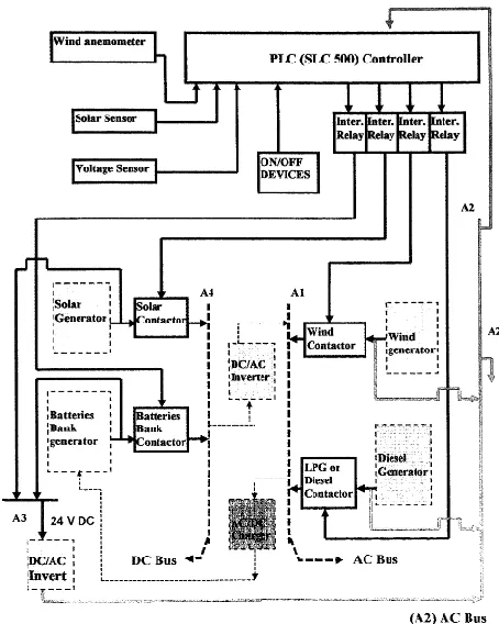
Figure 4 shows a block diagram of a control-developed method for two renewable energy generators, battery bank resource and emergency LPG I diesel generator, controlled by the PLC. The control method depends on three analogue sensors (wind anemometer, solar sensor, battery voltage sensor), digital inputs, Allen Bradley SLC 500, and four output contactors, four interference relays, as shown in highlighted line blocks in Fig. 1.13. Al is the final AC bus bar where all the generators deliver power to the customer's load. A2 is the bus bar after the diesel and wind generators directly to allow supplying the PLC and the rest of the control system. A3 bus bar is supplied from the solar generator and battery bank supplying inverter 2 to invert the DC voltage
into AC voltage, where upon it will supply A2 bus bar,
while A4 bus bar is the main DC power supplied from the solar and battery bank contactors. The three analogue sensors are connected to the analogue input card of the SLC 500. Any reading via any sensor will transfer it to the analogue input card. As the result of the loop powered method all the sensors are connected in series with the analogue input card.
Figure 4: Block diagram of the optimised control method for the renewable energygenerators.
[image:3.612.331.558.136.420.2]International Journal of Emerging Technology and Advanced Engineering
Website: www.ijetae.com
(ISSN 2250-2459, ISO 9001:2008 Certified Journal,
Volume 7, Issue 5, May 2017)
The last zone is the over-range zone, which the wind anemometer read above the energized working zone as a result of this; it will deactivate the output contactor.
[image:4.612.318.553.136.212.2]The SCL instruction in the software needs two parameters to start scaling the input value, this input value is detected by wind anemometer, which is connected by loop-powered method, these parameters are rate, and offset. To find these values using the linear relationship between input value and scaled range in Km/h, the following formulas helps to find these two values.
Figure 5: The Scaling graph.
Slope = scaled range/ input range. Off set = min scale - (min input value * slope).
Rate = (scaled range/input range) * 10000.
[image:4.612.53.281.270.420.2]To implements these calculated values from the linear relationship as shown above in the application software program, fill the SCL Instruction with these calculated values so that it starts reading from wind anemometer. Figure 6 shows the usage of SLC instruction (scaling instruction) in the software program. If all conditions for wind system are being met (permissible wind speed), then the wind anemometer transfers the value to the analogue input card (hardware). The control program with the help of the scaling instruction (SLC) starts calculation or working; as a result, it activates the internal relay so that the microprocessor of the PLC orders an output through the output card to activate wind contactor's coil, connecting wind generator to the AC bus bar. Using the wind anemometer as a demonstration method, to show the significant and key factor of the analogue sensor as a software and hardware to control the renewable energy system. Same method is used for both solar and battery voltage sensor.
Figure 6: SCL instruction bit for wind anemometer.
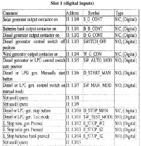
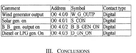
Digital inputs used in this code are connected to the input card (1746-1 *16) 24 V DC located in slot 1. Table 7 shows the comment, the address, symbol will be used in SCADA, and the type of each input connected to the slot 1 . Input I1 : 1. 0/8, I : 1. 0/9, I: I . 0/ 15 are not used (spares); the rest 13 inputs had been used.
Table 7: Slot 1 (digital inputs)
[image:4.612.324.558.318.560.2]International Journal of Emerging Technology and Advanced Engineering
Website: www.ijetae.com
(ISSN 2250-2459, ISO 9001:2008 Certified Journal,
Volume 7, Issue 5, May 2017)
[image:5.612.49.288.153.247.2]69 Table 8:
Slot 4 (output card)
III. CONCLUSIONS
Wind power can be an essential part of the renewable energy input, but it requires time and energy in design and implementation. The locating of wind systems and the infrastructure are vital the project being both safe and efficient. As a general rule, wind machines require a location where obstructions will not block the wind energy. Further, because of the enormous potential energy available with wind, the mounting structure must be able to withstand the most severe projected wind drag.
Photovoltaic cells convert sunlight directly into electricity and are made of semiconductors such as
crystalline silicon or various thin-film materials.
Photovoltaic can provide tiny amounts of power for watches, large amounts for the electric grid, and
everything in between. PV allows people the
opportunity to ignore traditional electrical power supply structures and meet their own power needs locally. In rural regions of the world today, where there are no power companies offering electricity, PV is often the technology of choice. PV is best suited for remote site applications that have small to moderate power requirements, or small power consuming applications even where the grid is in existence. A few power companies are also promoting limited grid-connected PV systems, but the large market for this technology is for stand-alone (off grid) applications.
Future work for implementing this research of renewable energy generators in a rural high-rise position
is highly recommended in order to increase the
dependency on fuel free generators. The major aim for
the future work is to increase the electricity generation
by wind and solar energy. The future research should
continue to achieve the optimum method for controlling the multiple renewable energy sources.
Because the control method is PLC driven, controlling the renewable energy generators remotely can he achieved by a SCADA system via telephone line and modem. Further work i s also recommended to investigate how to perform the optimum performance o f the control system.
Acknowledgment
We Dr. Wadah Aljaism, Dr Abdulhadi Alhassani, Dr Hashim Almusawaie and Miss Walla Hussain are acknowledging that the above study achieved by us.
REFERENCES
[1 ] "Wind Energy Basics". American Wind Energy Association.
Archived from the originalon 2010-09-23. Retrieved 2009-09-24.
[2 ]
http://www.treehugger.com/wind-technology/dragonfly-wind-
turbine-aims-blend-produce-power-low-wind- conditions.htmlhttps://www.wired.com/2015/05/future-wind-turbines-no-blades.
[3 ] https://www.wired.com/2015/05/future-wind-turbines-no-blades/.
[4 ]
http://www.wind-works.org/cms/index.php?id=64&tx_ttnews%5Btt_news%5D=3103 &cHash =be80a2ca690 fe1bcec1c0dc0af1e795b.
[5 ] Archived June 7, 2008, at the Wayback Machine.
[6 ] "Products & Services". Gepower.com. Retrieved 2013-11-06.
[7 ] "Technical Specs of Common Wind Turbine Models". Aweo.org.
[8 ]
http://cleantechnica.com/2014/04/07/vertical-axis-wind-turbines-great-1890-also-rans-2014/
[9 ] http://www.awsopenwind.org/downloads/documentation/Modeling
UncertaintyPublic.pdf.
[10 ] National Renewable Energy Laboratory (2001). Concentrating Solar
Power: Energy from Mirrors Retrieved December 18,
[11 ]"Photovoltaic Systems Research & Development: PV Roadmap". Archived from the original on January 29, 2010. Retri
[12 ]"PV Power Plants 2012" (PDF). Retrieved May 3, 2013.
[13 ]Solel.com, Ten facts about solar thermal power Retrieved December
18, 2008. Archived April 29, 2007, at the Wayback Machine.
[14 ]Mitsubishi Installs 50MW Energy Storage System to Japanese
Power Company In: globalspec.com. 11 März 2016, retrieved, 28 January 2017.
[15 ]World’s largest sodium-sulphur ESS deployed in Japan In:
bestmag.co.uk. 3 November 2016, retrieved, 28 January 2017.
[16 ]Batteries for Large-Scale Stationary Electrical Energy Storage (PDF;
826 kB), The Electrochemical Society Interface, 2010, (engl.).
[17 ]zdf-video, ZDF - Planet E – Schwungradspeicher.
[18 ]utilitydive.com, PG&E contracts for 75 MW of energy storage on its
![Solvent free Synthesis of 1,4-dihydropyrano[2,3-c]pyrazole Derivatives](data:image/gif;base64,R0lGODlhAQABAIAAAP///wAAACH5BAEAAAAALAAAAAABAAEAAAICRAEAOw==)