International Journal of Emerging Technology and Advanced Engineering
Website: www.ijetae.com (ISSN 2250-2459, ISO 9001:2008 Certified Journal, Volume 6, Issue 6, June 2016)
132
Inverted Stud Configuration in Steel Composite Beams
Akshay Sukhwani
1, Atul Vaibhav
2, Shivang Pathak
31B. Tech. Civil Engineering, National Institute of Technology Tiruchirappalli, Tamil Nadu, India – 620 015 2B. Tech. Civil Engineering, Motilal Nehru National Institute of Technology Allahabad, India – 211 004
3
Senior Engineer, Thornton Tomasetti Inc., Mumbai, India- 400 013
Abstract— The conventional composite beam comprises of concrete slab on metal deck placed on the top flange of the steel beam with shear connectors to resist the horizontal slippage and achieve a unified behaviour. However, the concrete placed above the top flange leads to additional depth of the section which decreases the clear ceiling height available. In this paper, a new steel-concrete composite beam type is devised making use of inverted studs below the top flange to achieve composite action between the steel and concrete elements. In many commercial and residential steel buildings there are architectural constraints and often heavier non-composite sections are used. Inverted stud configuration is an innovative way to enhance the capacity of the member with given depth restrictions. The behaviour of new composite beam is investigated using analytical tools and computational software – ANSYS. The results show the proposed configuration promises a lighter section with lower deflections and demand-capacity ratios as compared to the non-composite section.
Keywords—composite beam, depth restriction, inverted
stud, neutral axis, slab on metal deck.
I. INTRODUCTION
Composite structures are made from combining one or more materials to use the desired characteristics of each of the constituent material. Steel and concrete are the most ubiquitous materials known in the civil engineering profession.
Structural steel is strong in tension due to its initial linear elastic response to applied loading, characterizing steel as a ductile material. They are made up of plate elements and local and lateral buckling of those elements is the mode in which majority of failure occurs. Concrete is a more economic and more widely used construction material when compared to steel, though it is weaker in tension and will fail due to tensile cracking. On the account of having a heterogeneous composition, it is also susceptible to creep and shrinkage.
A steel-concrete composite structure thus has the intent of achieving a structure that prevents exposure of concrete to tensile forces and provides an overall compact cross section to subdue buckling failure.
An ideal design would involve the concrete being exposed to the compressive forces and the steel being exposed to the tensile forces [1]. The bond between steel and concrete elements is dire, without a closed bond composite action will not be accomplished and both the material will act individually having separate strain components.
Hence, every beam elements should deform identically as a single entity, with cross sections remaining plane when subjected to bending [5]. To achieve this bond and to enable the composite action i.e. steel and concrete acting as a single unit, shear connectors are used. They perform the functions of:
i. Transferring shear at the steel-concrete interface to prevent slippage, and
ii. Limiting separation at the steel-concrete interface thus preventing uplift [4].
A steel composite design would involve a concrete slab on a metal deck placed above the top flange of the steel beam and the neutral axis may lie either in concrete or steel depending upon the section property or load definition [7].
International Journal of Emerging Technology and Advanced Engineering
Website: www.ijetae.com (ISSN 2250-2459, ISO 9001:2008 Certified Journal, Volume 6, Issue 6, June 2016)
133
II. NEW COMPOSITE BEAM DETAILSA. Inverted Stud Configuration
In this paper, a new steel-concrete composite beam type is used in which concrete is placed below the top flange to achieve composite action between the steel and concrete elements. In many steel buildings there are architectural constraints and often heavier non-composite sections are used. This is an innovative way to enhance the capacity of the member with given depth restrictions using the proposed configuration.
B. Geometry
The effective flange width is a concept proposed by various codes to simplify the computation of stress distribution across the width of composite beam. In this paper, guidelines of AISC-360-10 edition for evaluating the effective slab width are used.
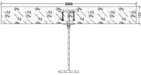
In contrast to the traditional composite design where concrete slab on metal deck is on the top flange, the paper focuses on the study where the concrete is below the top flange and studs are placed in inverted position below the top flange. A minimum 25 mm concrete is placed over the top flange to meet the fire rating requirements.
Figure 1 shows a composite section considered in this research.
Figure 1: Cross section of hybrid steel composite concrete with inverted studs (dimensions in mm).
C. Shear Connector Placement and design
The shear connectors (studs) may be considered either flexible or rigid in composite steel beam design. Flexible shear connectors are able to yield and undergo plastic deformation when resisting shear forces making them more ductile. Some slip between the concrete slab and steel beam or girder is expected to occur in flexible shear connector. In this paper, we consider 100 percent composite action with no slippage between the steel and concrete and that the shear connectors are rigid.
As flexible shear connectors are used for their ability to yield and undergo plastic deformation differential movement may occur at the steel-concrete interface, stifling the undesirable concrete cracking occurrence at the location of shear connectors. In this study headed shear studs are attached to the bottom face of top flange as shown in figure 1.
III. APPROACH TOWARDS THE PROBLEM
A. Analytical Approach
Assumptions: Concrete is assumed to behave as a linear isotropic material with failure strain of 0.0035 as per IS 456:2000. Structural steel is also assumed to behave as a linear isotropic material with yield strain of 0.002 as per IS 800:2007. Therefore, assumptions of Bending Theory
The composite section is assumed to behave monolithically thus implying 100 percent composite action. Unlike conventional composite design the failure is not assumed to occur when concrete and steel reaches their full plastic limit rather the failure will depend on the neutral axis and when concrete reaches 0.003 yield strain.
Methodology: A practical scenario of a commercial/ residential building with a usual beam span of 8m is studied in this paper. The non-composite and proposed configuration of inverted stud is analysed with analytical tools and commercially available program - SAP2000.
Uniform loading is applied on beams with various configurations to study the behaviour for each case. The following loading is taken into consideration:
Superimposed Dead Load = 6 kN/m2 Live Load = 4 kN/m2
It is assumed that the beams are spaced span/3 (2.67 m) center to center. The equivalent loading applied by considering tributary area of each beam is as follows:
Superimposed Dead Load = 16.02 kN/m Live Load = 10.68 kN/m
The results obtained from the analysis considering the above-mentioned loading are used in design calculations.
The moment capacity of the section is calculated using the following methodology:
Cconc + Csteel = Tsteel
where,
Cconc = Compression force in concrete
Csteel = Compression force in steel
[image:2.612.53.283.431.554.2]International Journal of Emerging Technology and Advanced Engineering
Website: www.ijetae.com (ISSN 2250-2459, ISO 9001:2008 Certified Journal, Volume 6, Issue 6, June 2016)
134
Based on above equation, the neutral axis is calculated which may lie either in the steel or in concrete depending upon the loading applied. The moment capacity of the section will depend on the location of neutral axis.The number of shear connectors required for 100 percent composite action can be found from the following:
N1 = V’/Qn
where,
N1= number of shear connectors uniformly spaced
between the point of zero moment and the point of maximum moment
V’= the horizontal shear force to be transferred between the concrete and steel
Qn = nominal shear strength of one shear
connector
Qn = 0.5 Asc √(fc’Ec) ≤ Rg Rp Asc Fu (AISC Equation I3-3)
where,
Asc = cross-sectional area of stud (sq in)
fc’ = 28-day compressive strength of concrete (ksi)
Ec = modulus of elasticity of concrete (ksi)
Rp = Rg = 1.0 for solid slabs (no formed steel
deck). For formed steel deck, Rp and Rg depend
upon deck properties.
Fu = minimum tensile strength of stud (ksi)
B. Computational Approach
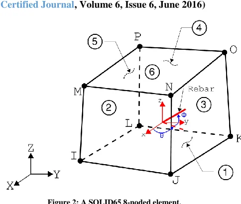
[image:3.612.329.571.119.324.2]A 3-D model of a composite beam is made in ANSYS software as shown in figure 2. The volumes are adaptively meshed using SOLID65 as the element and the corresponding material properties. Solid65 is an 8-noded element with 3 DOFs at each node: translations in the nodal x,y,z direction.
Figure 2: A SOLID65 8-noded element.
Dc defines the stress-strain matrix for concrete which depicts the isotropic nature. The Dc matrix is as follows:
[Dc] =
) 2 1 )( 1 (
E 2 ) 2 1 ( 0 0 0 0 0 0 2 ) 2 1 ( 0 0 0 0 0 0 2 ) 2 1 ( ) 1 ( 0 0 0 ) 1 ( 0 0 0 ) 1 ( The boundary condition for the beam is chosen as simply supported. The DOF of coincident nodes at steel and concrete interface are coupled to facilitate composite action.
International Journal of Emerging Technology and Advanced Engineering
Website: www.ijetae.com (ISSN 2250-2459, ISO 9001:2008 Certified Journal, Volume 6, Issue 6, June 2016)
[image:4.612.325.561.171.349.2]135
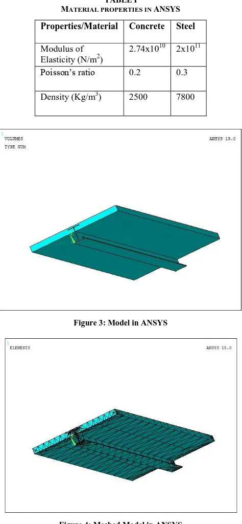
Steel cross-section of W12x53 embedded in 125 mm of concrete with 25 mm above the top flange was modeled. Figure 4 shows the model with adaptive meshing. Properties used while modeling are shown in Table I.TABLE I
MATERIAL PROPERTIES IN ANSYS
Properties/Material Concrete Steel
Modulus of Elasticity (N/m2)
2.74x10¹⁰ 2x10¹¹
Poisson’s ratio 0.2 0.3
Density (Kg/m3) 2500 7800
Figure 3: Model in ANSYS
Figure 4: Meshed Model in ANSYS
The loads are applied as surface pressure on the top concrete area. Figure 5 shows the deformed shape of the beam.
Figure 5: Deformed shape of Inverted composite beam in ANSYS
IV. RESULTS
As per the analysis using SAP2000 program and calculations based on strain theory, a non-composite beam of size W12x87 is required for the loading as specified in section III-A.
The study on the proposed inverted stud configuration show that a beam size of W12x53 is sufficient considering the composite action between the steel and concrete for the same loading conditions. Table II shows beam size summary for both the scenarios.
TABLE II
BEAM SIZE REQUIRED FOR PROPOSED CONFIGURATION VERSUS NON-COMPOSITE BEAM
S.No. Configuration Beam Size (AISC Shapes) 1 Non-composite beam W12x87
2 Inverted stud configuration W12x53
Table I shows significant reduction of 34 lb/ft (50.59 kg/m) in the steel tonnage. Therefore, the inverted stud configuration is more economical than non-composite beam.
[image:4.612.50.287.191.703.2]International Journal of Emerging Technology and Advanced Engineering
Website: www.ijetae.com (ISSN 2250-2459, ISO 9001:2008 Certified Journal, Volume 6, Issue 6, June 2016)
136
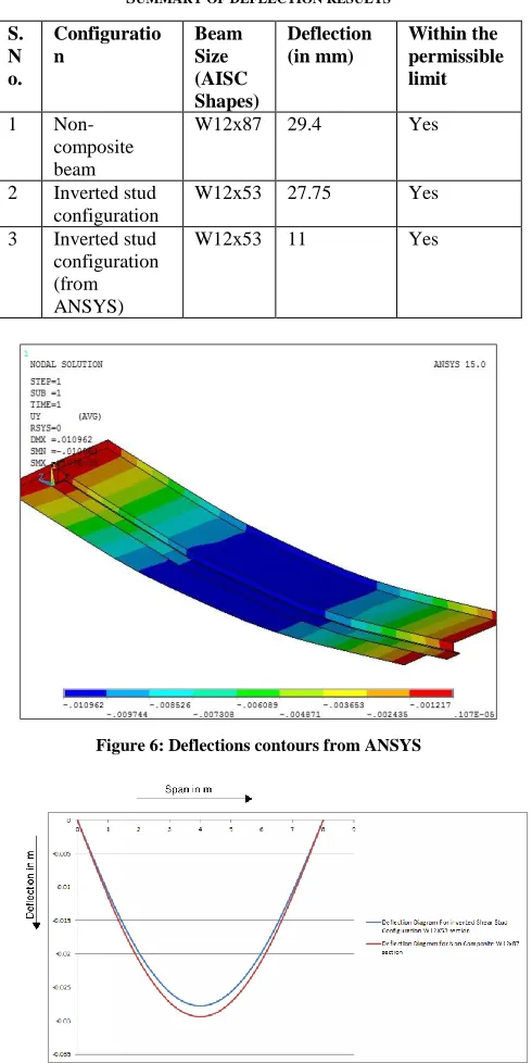
The summary of deflection results obtained from analytical and computational approach is shown in Table III and Figure 6. A comparison of deflections obtained from analysis is shown in Figure 7.TABLE III
SUMMARY OF DEFLECTION RESULTS
S. N o.
Configuratio n
Beam Size (AISC Shapes)
Deflection (in mm)
Within the permissible limit
1 Non-composite beam
W12x87 29.4 Yes
2 Inverted stud configuration
W12x53 27.75 Yes
3 Inverted stud configuration (from ANSYS)
W12x53 11 Yes
Figure 6: Deflections contours from ANSYS
Figure 7: Comparison of deflections in non-composite beam versus the proposed configuration
V. CONCLUSION
A new steel-concrete composite beam structure with an inverted shear stud configuration and concrete lying below the top flange outside the scope of IS 11384 - 1987 is developed in this study. A computational and analytical model of the composite beam is designed and examined to determine its behavior which is then compared with a non-composite beam both under gravity loadings for practical building construction. The resulting non-composite section is W12x87, whereas the hybrid section required is W12x53 saving us a tonnage of 50.59 kg/m with reduced deflections.
The inference can be made that in non-composite construction in order to incorporate a lighter section we will need deeper beams which can exceed the depth due to floor to floor height restriction. And in such cases we can effectively provide a shallower section lying within the depth limit by going for the composite construction as proposed in this paper.
In many practical situations when conventional composite configuration for beams cannot be adopted due to stringent depth restrictions, the proposed composite configuration using inverted studs can be preferably used.
REFERENCES
[1] ASCE-7-2010 Minimum design loads for buildings and other structures.
[2] Bouazaoui, L., Perrnot, G., Delmas, Y. & Li, A. 2007. Experimental study of bonded steel concrete composite structures. Journal of Constructional Steel Research, 63, 1268-1278.
[3] Cook, J. P. 1977. Composite Construction Methods, Sydney, John Wiley & Sons.
[4] Davies, C. 1975. Steel-Concrete Composite Beams for Buildings, London, George Godwin Limited.
[5] Fazekas, G. A. 1967. A note on the bending of Euler beams. Journal of Engineering Education, 57.
[6] Indian Standard IS-3935 - Code of practice for composite construction.
[7] Jurkiewiez, B. & Hottier, J. M. 2005. Static behaviour of a steel– concrete composite beam with an innovative horizontal connection. Journal of Constructional Steel Research, 61, 1286-1300.
[image:5.612.49.294.201.690.2]