International Journal of Emerging Technology and Advanced Engineering
Website: www.ijetae.com (ISSN 2250-2459, ISO 9001:2008 Certified Journal, Volume 4, Issue 5, May 2014)
206
CFD Analysis of Cylindrical Pin with Trapezoidal Fin Heat
Sink using ANSYS Fluent 14.0
Irfan Vohra
1, Mohammad Azim Aijaz
2, Dr. B. B. Saxena
31
M. Tech. Scholar, 2Assistant Professor, 3H.O.D., Mechanical Engineering Department, PCST Bhopal (M.P), INDIA Abstract— In our analysis, Computational Fluid Dynamics
was developed on Ansys 14.0. The governing equations are solved by adopting a control volume-based finite-Volume method with a power-law scheme on an orthogonal non-uniform staggered grid. The coupling of the velocity and the pressure terms of momentum equations are solved by the Computational Fluid Dynamics. The Cylindrical Pin with Trapezoidal Fin Heat Sink is composed of a plate fin heat sink and some Cylindrical pins between plate fins. Heat transfer taken in air and aluminum as a pin fin material. To Study of thermal Performance of circular pin fin. and get the value of heat transfer coefficient, surface Nusselt number, thermal resistance and pressure drop for the heat sink of the different circular pin with trapezoidal fin profile at different velocity and constant heat input 10w and predict temperature distribution along the cylindrical pin with Trapezoidal fin. The purpose of this study is to examine the effects of the configurations of the pin-fins design .Thermal resistance , Pressure drop, and Nusselt number is compared with experimental results and simulation results[4]and design of circular pin of various diameter 4.0mm,3.75mm,3.50mm with trapezoidal fin of various thickness 1.0mm, 0.9mm, 0.8mm various wind velocity of 6.5 m/s,9.5m/s,12.5m/s of 30 cases. The results show that the Circular Pin of 3.75 mm diameter with trapezoidal Fin of 0.8 mm tip thickness heat Sink at 12.5m/s wind velocity has better unnaturally performance pressure because of max Nusselt number 1066.93 and heat transfer coefficient 51.60 W/M2K and thermal resistance 0.47 than the plate fin heat sink and other cases.
Keywords— Heat sink, Heat transfer, Thermal resistance,
Nusselt Number, Pressure drop, Cylindrical Pin Fin Heat Sink (CPFHS), heat transfer coefficient, and Heat flux.
I. INTRODUCTION
With the increase in heat dissipation from
microelectronics devices and the reduction in overall form factors, thermal management becomes a more important element of electronic product design [1]. Both the performance reliability and life expectancy of electronic equipment are inversely related to the component temperature of the equipment. The relationship between the reliability and the operating temperature of a typical silicon semi conductor device shows that a reduction in the temperature corresponds to an exponential increase in the reliability and life expectancy of the device.
Therefore, long life and reliable performance of a component may be achieved by effectively controlling the device operating temperature within the limits set by the device design engineers.
The effective use of an electrical component is limited by its maximum operational junction temperature. To achieve a desired component temperature, excess heat dissipated by the device must be transferred to the environment [2]. The most common method for transferring heat from the component to the environment is to use a heat sink. To estimate a component’s junction temperature, a required value is the heat sink’s thermal resistance. The thermal resistance of heat sink can be determined analytically or experimentally.
In electronic systems, a heat sink is a passive component that cools a device by dissipating heat into the surrounding air. In computers, heat sinks are used to cool electronic components. Heat sinks are used with high-power semiconductor devices such as power transistors and optoelectronic devices such as lasers and light emitting diodes (LEDs), wherever the heat dissipation ability of the basic device package is insufficient to control its temperature.
II. OBJECTIVE OF WORK
The main objective of the current work is
1. Validation of the CFD models by comparing the
present simulated results with the Experimental result by Yue-Tzu Yang & Huan-Sen Peng [3]and simulation result of CFD analysis for elliptical pin fin by Anil Rao[4].
2. To predict velocity profiles, and temperature for
different wind velocity (6.5,9.5 & 12.5m/s) on the heat sink.
3. To simulate the heat sink of the circular pin fin having
different diameter of 1mm, 0.9mm and 0.8mm and different velocity (6.5, 9.5 & 12.5m/s) for constant heat input.
International Journal of Emerging Technology and Advanced Engineering
Website: www.ijetae.com (ISSN 2250-2459, ISO 9001:2008 Certified Journal, Volume 4, Issue 5, May 2014)
207
5.To get the value of heat transfer coefficient, surface
Nusselt number, thermal resistance and pressure drop for the heat sink of the different circular pin fin profile at different velocity and constant heat input 10w.
6.To predict temperature distribution along the
Trapezoidal pin fin.
III. CFDMODELING
Computational Fluid Dynamics (CFD) is the science of determining numerical solution of governing equation for the fluid flow whilst advancing the solution through space or time to obtain a numerical description of the complete flow field of interest. The equation can represent steady or unsteady, Compressible or Incompressible, and in viscid or viscous flows, including non ideal and reacting fluid behavior. The particular form chosen depends on intended application. The state of the art is characterized by the complexity of the geometry, the flow physics, and the computing time required obtaining a solution. The purpose of this research work is to simulate pressure Drop and heat transfer in a heat sink and validate the simulation with actual experimental result and simulation results[3,4] using fluent software. Different solvers and turbulence models have been developed in CFD SOFTWARE for predicting Thermal Resistance, heat transfer coefficient, Nusselt number using Plate fin heat sink and Cylindrical fin pin heat sink for various wind velocity. Computational fluid dynamics (CFD) is a computer-based simulation method for analyzing fluid flow, heat transfer, and related phenomena such as chemical reactions. This dissertation uses CFD for analysis of flow and heat transfer. It will be advantageous to use CFD over traditional experimental-based analyses, since experiments have a cost directly proportional to the number of configurations desired for testing, unlike with CFD, where large amounts of results can be produced at practically no added expense. In this way, parametric studies to optimize equipment are very inexpensive with CFD when compared to experiments. The dimensions of the computational domain heat sink Were based on the work by Yu et al [1]. After this process the constraint are applied and this way the model is achieved in modeling software Creo Parametric 1.0.
Table 1.
Geometry Parameters of Heat Sink Fin No, N Fin height, H(mm) Fin Length, L(mm) Fin thickness , t (mm)
Fin-to-fin distance, ξ(mm)
[image:2.612.355.571.166.380.2]9 10 50 1 to 0.8 8
Table- 2
Experimental[3] and Simulation [4] Result for the Plate fin Heat Sink
Observation Table:-Thermal Resistance
Graph-1 Experimental[3] and Simulation [4] Results of Thermal Resistance for the Plate fin Heat Sink
[image:2.612.326.570.482.694.2]According to results we are very nearest to simulation results of Thermal Resistance. It can validate our results
Table-3
Experimental and Simulation Result for the Plate fin Heat Sink
Observation Table:-Pressure Drop
Graph- 2 Experimental[3] and Simulation [4] Results of Pressure Drop for the Plate fin Heat Sink
Wind Velocity (m/s) Experimental Result[3], Pa Simulation Results[4],Pa Simulation Results,Pa
6.5 20 23.3 20.80
9.5 37.5 40.6 37.22
12.5 56 59.5 57.37
Wind Velocity (m/s) Experimental Result[3] K/W Simulation Results[4] K/W Simulation Results K/W
6.5 1.35 1.79 1.82
9.5 1.15 1.47 1.46
International Journal of Emerging Technology and Advanced Engineering
Website: www.ijetae.com (ISSN 2250-2459, ISO 9001:2008 Certified Journal, Volume 4, Issue 5, May 2014)
208
According to results of Pressure Drop we are very nearest to Experimental result of Pressure Drop. It can validate our results.
Table- 4
Experimental and Simulation Result for the Plate fin Heat Sink
Observation Table:- Nusselt Number:
Graph- 3 Experimental[3] and Simulation [4] Results of Nusselt Number of the Plate fin Heat Sink
According to results of Nusselt number we are nearest to Simulation result of Nusselt number. It can validate our results.
Table-5
Dimensions of Cylindrical Pin withTrapezoidal fin.
Wind Velocity
(m/s)
Experim ental Result[3]
Simulatio n Results[4]
Simulati on Results 6.5 570 888.78 698.691
9.5 680 1026.95 792.5209
12.5 750 1170.47 864.998
Case no
Dia of Pin in mm
Tip Thickness(t)
in mm
Velocity in m/s
Case 1 Plane 1 6.5
Case 2 Plane 1 9.5
Case 3 Plane 1 12.5
Case 4 4 1 6.5
Case 5 4 1 9.5
Case 6 4 1 12.5
Case 7 4 0.9 6.5
Case 8 4 0.9 9.5
Case 9 4 0.9 12.5
Case 10 4 0.8 6.5
Case 11 4 0.8 9.5
Case 12 4 0.8 12.5
Case 13 3.75 1 6.5
Case 14 3.75 1 9.5
Case 15 3.75 1 12.5
Case 16 3.75 0.9 6.5
Case 17 3.75 0.9 9.5
Case 18 3.75 0.9 12.5
Case 19 3.75 0.8 6.5
Case 20 3.75 0.8 9.5
Case 21 3.75 0.8 12.5
Case 22 3.5 1 6.5
Case 23 3.5 1 9.5
Case 24 3.5 1 12.5
Case 25 3.5 0.9 6.5
Case 26 3.5 0.9 9.5
Case 27 3.5 0.9 12.5
Case 28 3.5 0.8 6.5
Case 29 3.5 0.8 9.5
International Journal of Emerging Technology and Advanced Engineering
Website: www.ijetae.com (ISSN 2250-2459, ISO 9001:2008 Certified Journal, Volume 4, Issue 5, May 2014)
209
These equations solve by the fluent software. The conservation laws of physics form the basis for fluid flow governing equation. The dimensions of the computational domain heat sink were based on the work by Yu et al [3].Geometry of Plate fin heat sink and Cylindrical pin-fin heat sink are shown in fig.1, 2. The governing equations used in CFD for fluid flow and heat transfer are based upon the principles of conservation of mass, momentum, and energy [4].
[image:4.612.362.525.122.224.2]IV. MATERIAL PROPERTIES
Table- 6 Materials Properties
(a) Air (fluid) (b) Aluminum (solid)
V. MESHING OF THE DOMAIN
Experimental in Para solid format (: .x-t) to the ansys work bench Design modular. Then defining the air domain and solid domain. There for further Processing. Defining the mesh to the domain. Total number of elements 50502 & nods 11928 were employed to assess the grid independence in the Pin Fin Heat Sink case. A total number of elements are 2210 and nodes are 3675 in the Plate fin case.
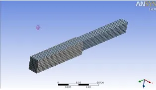
[image:4.612.56.262.239.413.2]Fig 1 (Geometry 1) Mesh of Plane pin fin Heat Sink Model
Fig 2 Mesh of Circular Pin with Trapezoidal fin Heat Sink Model
VI. BOUNDARY CONDITION
Given the periodic structure of the heat sinks, only one flow passage is investigated. The computational domain employed is shown in Fig. 2 The material of the heat sink is aluminum. The bottom of the computational domain is heated at a constant heat transfer rate of 10W and different velocity (6.5, 9.5 and 12.5 m/s).The flow is assumed to be three dimensional, incompressible, steady, turbulent, and since the heating is low, constant air properties. Radiation effect is ignored.
VII. GOVERNING EQUATION ARE SOLVED BY CFD
This section is a summary of the governing equations used in CFD to mathematically solve for fluid flow and heat transfer, based on the principles of conservation of mass, momentum, and energy. These equations solve by the fluent software. The conservation laws of physics form the basis for fluid flow governing equations. The continuity, momentum and energy equation are written below.
Law Of Conservation Of Mass:
Momentum Equation:
X-momentum:
Y-momentum:
Properties Air Aluminium Density, ρ 1.225 Kg/m3 2719 Kg/m3
Thermal
Conductivity, K
0.0242
W/m-K
202.4 W/m-K
Specific Heat,
Cp
1006.43
J/Kg-K
871 J/Kg-K
Viscosity, μ 1.7894x10⁻⁵
Kg/m-s
[image:4.612.89.246.543.634.2]International Journal of Emerging Technology and Advanced Engineering
Website: www.ijetae.com (ISSN 2250-2459, ISO 9001:2008 Certified Journal, Volume 4, Issue 5, May 2014)
210
Z-momentum:
Energy Equation:
Equation Of State:
In the analysis, the flow is assumed to 3- dimensional, turbulence, incompressible and steady flow. Buoyancy and radiation heat transfer are not consider in the crimped fin analysis. All the thermodynamics property i.e. (P-V-T) is assumed to constant. The K−ε turbulent model is used for describe the air flow characteristics.
VIII. TEMPERATURE DISTRIBUTION IN DIFFERENT TIP
THICKNESS AND DIFFERENT CIRCULAR DIAMETER OF PIN FIN
Fig 3 : (Case21) Temperature Distribution 304.67 K for Circular Pin of 3.75 mm dia Trapezoidal fin of Tip Thickness 0.9 mm Heat Sink with 12.5 m/s.
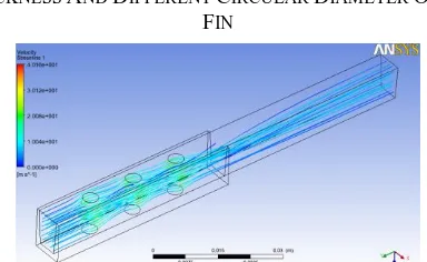
IX. VELOCITY DISTRIBUTION IN DIFFERENT TIP THICKNESS AND DIFFERENT CIRCULAR DIAMETER OF PIN
FIN
[image:5.612.351.535.121.230.2] [image:5.612.346.538.261.379.2]International Journal of Emerging Technology and Advanced Engineering
Website: www.ijetae.com (ISSN 2250-2459, ISO 9001:2008 Certified Journal, Volume 4, Issue 5, May 2014)
211
Table- 7
Result Table of Cylindrical Pin with Trapezoidal fin.
Graph 4 xyz Velocity-Thermal Resistance
The above graph shows the relation between the thermal resistance and velocity of all the cases the lines shows the geometrical variation we have taken for the study. Series 1 is the validation case it is plane fin, All the geometrical variation are below the experimental data. The Lowest value of the Thermal resistance is in Series no 4. It is the best Combination of Geometrical Property.
Case no Dia in mm
Tip Thickness(t)
in mm
Velocity in m/s
Press. Drop (Pa)
Base temp(K)
Temp. Difference.
(k)
Thermal Resistivity(K/W)
Heat Transfer coefficient U, W/m2k
Nusselt No( Nu)
Case 1 Plane 1 6.5 20.80 318.18 18.18 1.82 33.82 698.691
Case 2 Plane 1 9.5 37.22 314.60 14.60 1.46 38.36 792.5209
Case 3 Plane 1 12.5 57.37 312.37 12.37 1.24 41.87 864.998
Case 4 4 1 6.5 307.92 307.72 7.72 0.77 42.01 868.025
Case 5 4 1 9.5 596.70 306.48 6.48 0.65 44.95 928.8035
Case 6 4 1 12.5 988.49 305.54 5.54 0.55 47.33 977.9855
Case 7 4 0.9 6.5 318.70 307.72 7.72 0.77 41.80 863.7145
Case 8 4 0.9 9.5 626.72 306.31 6.31 0.63 45.14 932.5865
Case 9 4 0.9 12.5 1031.58 305.39 5.39 0.54 47.54 982.1905
Case 10 4 0.8 6.5 320.09 306.83 6.83 0.68 43.98 908.772
Case 11 4 0.8 9.5 629.84 305.41 5.41 0.54 47.60 983.4825
Case 12 4 0.8 12.5 1039.75 304.53 4.53 0.45 50.19 1036.975
Case 13 3.75 1 6.5 280.99 306.97 6.97 0.70 44.28 914.9705
Case 14 3.75 1 9.5 547.81 305.53 5.53 0.55 47.83 988.294
Case 15 3.75 1 12.5 901.51 304.63 4.63 0.46 50.27 1038.545
Case 16 3.75 0.9 6.5 260.32 306.98 6.98 0.70 43.95 908.0445
Case 17 3.75 0.9 9.5 509.11 305.54 5.54 0.55 47.87 989.015
Case 18 3.75 0.9 12.5 837.92 304.66 4.66 0.47 49.83 1029.562
Case 19 3.75 0.8 6.5 244.25 306.94 6.94 0.69 45.87 947.7665
Case 20 3.75 0.8 9.5 474.30 305.56 5.56 0.56 49.35 1019.548
Case 21 3.75 0.8 12.5 782.84 304.67 4.67 0.47 51.60 1066.093
Case 22 3.5 1 6.5 220.11 307.20 7.20 0.72 44.46 918.6065
Case 23 3.5 1 9.5 423.70 305.78 5.78 0.58 48.19 995.7015
Case 24 3.5 1 12.5 686.62 304.89 4.89 0.49 50.74 1048.294
Case 25 3.5 0.9 6.5 209.66 307.26 7.26 0.73 44.53 919.947
Case 26 3.5 0.9 9.5 403.90 305.79 5.79 0.58 48.08 993.359
Case 27 3.5 0.9 12.5 662.55 304.88 4.88 0.49 50.45 1042.352
Case 28 3.5 0.8 6.5 207.06 307.24 7.24 0.72 44.15 912.228
Case 29 3.5 0.8 9.5 398.33 305.79 5.79 0.58 47.66 984.7755
International Journal of Emerging Technology and Advanced Engineering
Website: www.ijetae.com (ISSN 2250-2459, ISO 9001:2008 Certified Journal, Volume 4, Issue 5, May 2014)
212
Graph 5 xyz Velocity –Pressure
The above graph shows the relation between the Pressure Drop and velocity of all the cases the lines shows the geometrical variation we have taken for the study. Series 1 is the validation case it is plane fin, All the geometrical variation are below the experimental data. The Lowest value of the Pressure Drop is in Series no 10. It is
the best Combination of Geometrical Property.
Graph 6 xyz Velocity-Nusselt Number
The above graph shows the relation between the Nusselt Number and velocity of all the cases the lines shows the geometrical variation we have taken for the study. Series 1 is the validation case it is plane fin, All the geometrical variation are above the experimental data. The Highest value of the Nusselt number is in Series no 07. It is the best Combination of Geometrical Property.
Graph 7 xyz Velocity-Heat transfer coefficient
The above graph shows the relation between the Heat Transfer Coefficient and velocity of all the cases the lines shows the geometrical variation we have taken for the study. Series 1 is the validation case it is plane fin, All the geometrical variation are above the experimental data.
The Highest value of the Heat transfer coefficient is in
Series no 07. It is the best Combination of Geometrical Property.
X. CONCLUSION
As we have discussed in results above the thermal resistivity, Nusselts number ,heat transfer coefficient ,Pressure drop, we are here to conclude that maximum pressure drop is in (case no 9) of 1039.58 Pascals and minimum pressure drop 207.06 Pascal that is in (case no 28) and also we have seen with Maximum thermal resistance is 0.77 in (case no 4) and minimum thermal resistance is 0.45 in (case no 12).Also one of our concentration through nusselt no, the Maximum value of Nusselt no 1066.093 in (case no 21).and Min value of Nusselt no 863.715 in (case no7).Similarly Max. value of heat transfer coefficient is 51.60 in (case no 21) and minimum heat transfer coefficient 41.80 in (case no 7). This discussion direct us to understand the best combination of fin arrangement. Most of the values in our favour comes in (case no 21). That is Pin dia 3.75 mm with tip thickness 0.8 mm at 12.5 m/s velocity with small consideration of Pressure drop 130 Pascal higher than (case no 30) but thermal resistance is 0.47 in place of 0.49.
XI. APPLICATION
Since heating power is uniform over the bottom of the fin base, thermal resistance of CPFHS always lower than PFHS. However heating of CPU is are always center of concentration on the fin base in real engineering application. Circular pin fin heat sink creates more pressure drop than elliptical pin fin heat sink, so it can be use according to the cooling requirement.
REFERENCES
[1] http://www.techterms.com/defination [2] http://en.wikipedia.org//wiki/heatsink
[3] Yue-Tzu Yang “ Investigation of planted pin fins for heat transfer enhancement in plate fin heat sink”
[4] Anil Kumar Rao ” CFD Analysis Of Elliptical Pin Fin Heat Sink”. [5] Ambeprasad.S.Kushwaha “Comparative Study of Rectangular,
Trapezoidal and Parabolic Shaped Finned Heat sink “.
[6] Selma Ben Saad “Single phase pressure drop and two-phase distribution in an offset strip fin compact heat exchanger” Applied Thermal Engineering, Volume 49, 31 December 2012, Pages 99-105
[7] Vijaisri Nagarajan “Hydraulic and thermal performances of a novel configuration of high temperature ceramic plate-fin heat exchanger” Applied Energy, Volume 113, January 2014, Pages 589-602 [8] Bernd Ameel “On fin efficiency in interrupted fin and tube heat
International Journal of Emerging Technology and Advanced Engineering
Website: www.ijetae.com (ISSN 2250-2459, ISO 9001:2008 Certified Journal, Volume 4, Issue 5, May 2014)
213
[9] Li-Zhi Zhang “Conjugate Heat Transfer in Plate-Fin and Tube Heat Exchangers” Conjugate Heat and Mass Transfer in Heat Mass Exchanger Ducts, 2013, Pages 255-274
[10] Weiping Wang “Numerical study on hydrodynamic characteristics of plate-fin heat exchanger using porous media approach” Computers & Chemical Engineering, Volume 61, 11 February 2014, Pages 30-37.
[11] Fatih Selimefendigil “Fuzzy-based estimation of mixed convection heat transfer in a square cavity in the presence of an adiabatic inclined fin”International Communications in Heat and Mass Transfer, Volume 39, Issue 10, December 2012, Pages 1639-1646 [12] Chan Hyeok Jeong “Numerical investigation of thermal
enhancement of plate fin type heat exchanger with creases and holes in construction machinery” Applied Thermal Engineering, Volume 62, Issue 2, 25 January 2014, Pages 529-544.
[13] Bernd Ameel “Optimization of X-shaped louvered fin and tube heat exchangers while maintaining the physical meaning of the performance evaluation criterion” Applied Thermal Engineering, Volume 58, Issues 1–2, September 2013, Pages 136-145
[14] Cheen Su An “Analysis of heat-transfer performance of cross-flow fin-tube heat exchangers under dry and wet conditions” International Journal of Heat and Mass Transfer, Volume 55, Issues 5–6, February 2012, Pages 1496-1504
[15] Lingen Chen “Constructal entransy dissipation rate minimization for tree-shaped assembly of fins” International Journal of Heat and Mass Transfer, Volume 67, December 2013, Pages 506-513.
[16] Jiin-Yuh Jang, “A study of 3-D numerical simulation and comparison with experimental results on turbulent flow of venting flue gas using thermoelectric generator modules and plate fin heat sink” Energy, Volume 53, 1 May 2013, Pages 270-281
[17] Ilker Tari, “Natural convection heat transfer from inclined plate-fin heat sinks” International Journal of Heat and Mass Transfer, Volume 56, Issues 1–2, 1 January 2013, Pages 574-593
![Table- 2 Experimental[3] and Simulation [4] Result for the Plate fin Heat Sink](https://thumb-us.123doks.com/thumbv2/123dok_us/8714836.882796/2.612.355.571.166.380/table-experimental-simulation-result-plate-fin-heat-sink.webp)