Even Mode Network Model for Multi-band and Compact
Modified Rectangular Microstrip Antennas
Amit A.
Deshmukh
EXTC, DJSCOE Vile – Parle (W), Mumbai, India
Tejal A. Tirodkar
EXTC, DJSCOE Vile – Parle (W), Mumbai, India
Ankita R. Jain
EXTC, DJSCOE Vile – Parle (W), Mumbai, India
K. P. Ray
SAMEER, IIT Campus, Powai
Mumbai, India
ABSTRACT
The multi-port network model is a simpler tool to analyze microstrip antennas on thinner substrates. While analyzing modified shaped microstrip antennas, the multi-port network model consists of larger number of segments which increases the complexity of the model. In this paper, first multi-port network models of multi-band and compact modified rectangular microstrip antennas are discussed. Further by using the symmetry of multi-port network models, a simpler even mode network equivalent model is proposed. The even mode network model solves only half of the network and thereby reduces the complexity of the multi-port network model. It gives closer match with multi-port network model result in terms of resonance frequency, input impedance and voltage distribution.
Keywords
Rectangular microstrip antenna, Multi-port network model, Even mode network model, Multi-band microstrip antenna, Compact microstrip antenna
1.
INTRODUCTION
The compact microstrip antenna (MSA) is realized either by placing the shorting post or plate along the zero field line at the fundamental patch mode or by cutting the slot at an appropriate position inside the patch [1, 2]. The dual band and triple band MSAs are also realized either by placing an open circuit nearly quarter wavelength stub on the edges of the patch or by cutting the slot like U-slot and rectangular slots inside the patch, or by using the combination of slot and stub [3 – 5]. These compact and multi-band MSAs finds wide applications in mobile communications, Wi-Fi networking and in laptops. For analyzing MSAs different techniques based on the magnetic current model around the patch periphery or electric current model on the patch are available [1, 2]. Out of them, multi-port network model (MNM) which is based upon the magnetic current model around the patch periphery, is an simpler and efficient tool for analyzing MSAs on thinner substrates (h) (h < 0.040) [1, 2]. In MNM, fields inside the patch are modeled using the Green’s function of the patch geometry and outside the patch they are modeled using radiation and surface wave conductance which accounts for radiation from the patch and the surface waves. For using MNM in modified shaped MSAs, the patch is first divided into regular shapes for which the Green’s function is available and further by using either segmentation or de-segmentation technique, the input impedance of the composite configuration is calculated. Using the reported formulations in MN model, the voltage distribution around the patch periphery is
calculated which is very useful in understanding the mode excitation at a given frequency. While using segmentation method in analyzing compact and multi-band MSAs, numbers of segments in their MN model are higher which increases the complexity of the network. The de-segmentation technique involves lesser number of segments in its MN model but it is relatively complex method as compared to the segmentation method.
When the MN model of MSA is symmetrical across the feed point axis then its equivalent even mode network model has been used to calculate the input impedance and voltage distribution around the patch periphery, and it gives closer match with the MN model result [6]. In this paper, first MNM and an even mode network models for RMSA are discussed. Further the MN models for compact slot cut RMSA like H-shaped and ring MSAs and dual and triple band slot cut and stub loaded RMSAs are proposed. By using the symmetry of MN models across the feed point axis, an even mode network models for compact as well as multi-band RMSAs are proposed. The even mode network model reduces the number of segments by half and thus reduces the complexity of the structure. Further it gives the same results in terms of resonance frequency, input impedance and voltage distribution to that given by their MN model. Thus for any complex shaped MSAs, which are symmetrical across feed point axis, their even mode model of the equivalent MN model can be solved. All the compact and multi-band RMSAs were first analyzed using IE3D software followed by MNM, even mode modeling [7]. In some of the cases, patch was fabricated and the measurement was carried out using R & S vector network analyzer.
2.
MNM AND EVEN MODE ANALYSIS
OF RMSA
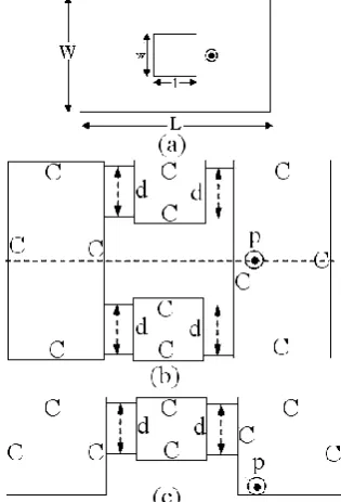
simulated values using IE3D are, (38.02 – j 5.0) and 1610 MHz, respectively. The matrix size for MN model is 44 x 44. The MN model of RMSA is symmetrical across feed point axis. Hence only half of the portion is solved, which leads to its even mode network model as shown in Fig. 1(c). The RMSA width is reduced by half which reduces the number of ports along the radiating edge by half. This maintains the same port width to that used in MN model. The ports are taken along two radiating and one non-radiating edges. No ports are taken along the edge where the feed point is present. This reduces Z-matrix size to (Na + Nb) x (Na + Nb). The values of effective dielectric constant, loss tangent, and total conductance at each port are kept the same. They are not re-calculated using the reduced width as width is reduced only for the computational simplicity. Further Zin calculated by using even mode network is divided by two to obtain the input impedance as that will be given by its MN model. The Zin and fr calculated by using even mode network model are (42.12 – j0.7) and 1617 MHz. The matrix size order is reduced to 22 x 22 in the even mode network model. The Zin and frequency are very close to each other in the two methods and the size of the Z-matrix is reduced by a factor of 3 in the even mode method. This reduces computation time by more than half. Thus the above method is very useful in MNM analysis of complex shaped MSAs, which involves larger number of segments.
Fig. 1 (a) RMSA, its (b) MN and (c) even mode network model
3.
MNM AND EVEN MODE NETWORK
MODEL FOR MULTI-BAND RMSAs
More commonly dual band RMSA is realized by cutting the slot inside the patch. Here dual band pair of step slot cut RMSA is studied as shown in Fig. 2(a) [8]. The step slots are cut along the non-radiating edges of the RMSA. For the dimensions shown in figure, simulated dual frequencies and bandwidth (BW) are 661, 893 MHz and 11, 15 MHz, respectively, as shown in Fig. 2(c). The pair of step slot cut RMSA is analyzed using its MN model as shown in Fig. 2(b). The MSA is divided into six rectangular segments. The ‘C’ are the ports taken along the edges of the individual segments and‘d’ are the ports taken along segmented edges. The coaxial feed is represented by port ‘p’. Using the segmentation method the Zin is calculated and is shown in Fig. 2(c). The dual frequencies and BW’s are 640 and 900 MHz and 12 and 18 MHz, respectively. The Zin at the two frequencies is (57.6 – j 2.2) and (63 – j 8.3), respectively.
[image:2.595.355.500.270.726.2] [image:2.595.67.271.351.726.2]The voltage distribution across the RMSA and step slot is calculated by using the formulation reported in [1] and it is shown in Fig. 3(a – d). At first frequency (f1), a wavelength variation is present around the total slot length with voltage minima towards the shorted slot ends, indicating that f1 is governed by the mode introduced by slot. The radiation pattern at f1 shows higher cross polarization levels due to the asymmetrical voltage distribution around the patch edges. At second frequency (f2), patch mode is dominant as half wavelength variation is present along the non-radiating edge of the patch as well as along the slot length. The radiation pattern at this frequency is in the broadside direction.
Fig. 3 (a – d) Voltage distribution for step slot cut RMSA
The MN model of step slot cut RMSA consist of six segments and its Z-matrix size is 312 x 312. The MN model of pair of step slot cut RMSA is symmetrical across the feed point axis, hence to reduce the number segments, an even mode network of step slot cut RMSA is proposed as shown in Fig. 4(a). The even mode model consist of five segments. The widths of the segments which are symmetrical across the feed point axis and the ports along them are reduced by half. The effective dielectric constant, loss tangent, radiation and surface wave conductance at each port are kept the same. Further by using segmentation method, Zin is calculated. Using even mode network, Z-matrix size is reduced to 156 x 156. The input impedance plot and voltage distributions at the two frequencies using even mode network are shown in Fig. 4(b) and 5(a – d), respectively. The dual frequencies and BW’s are 640 and 900 MHz and 12 and 18 MHz, respectively. The Zin at the two frequencies is (54.9 – j 5.6) and (59.8 – j 0.33), respectively. The resonance frequencies, input impedance and voltage distribution obtained using even mode model are similar to that obtained using MN model results. The results for step slot cut RMSA are given in Table 1.
Fig. 4 (a) Even mode network and (b) input impedance plots for dual band step slot cut RMSA
[image:3.595.85.253.205.743.2] [image:3.595.347.503.290.546.2]technique, Zin is calculated. The frequencies and BWs using MN model are 680, 784 and 978 MHz and 11, 11 and 12 MHz, respectively as shown in Fig. 6(c). To reduce the number of segments in the MN model, an even mode network model for triple band RMSA is proposed as shown in Fig. 6(d).
Fig. 5 (a – d) Voltage distribution for step slot cut RMSA using even mode network model
The even mode model consists of four rectangular segments and it also reduces the Z-matrix size for the equivalent network. Using the segmentation method the Zin is calculated. The frequencies and BWs calculated using even mode network are 681, 784 and 977 MHz and 11, 12 and 12 MHz, respectively as shown in Fig. 6(c). These results are very close
to that obtained using MN model results as well as the experimental results.
Fig. 6 (a) Pair of slot cut stub loaded RMSA, its (b) MN model, its (c) input impedance plot and its (d) even mode network model
[image:4.595.339.522.101.623.2] [image:4.595.89.250.142.662.2]using MN model are 770, 952 and 1100 MHz and 16, 18 and 22 MHz. The frequencies and BWs using even mode network are 771, 953 and 1100 MHz and 15, 17 and 23 MHz, respectively as shown in Fig 7(d).
Fig. 7 (a) U-slot cut stub loaded RMSA, its (b) MN model, its (c) even mode network model and its (d) input impedance plot
For the dimension shown in Fig. 7(a), triple frequency response is experimentally verified. The measured frequencies and corresponding BWs are, 792, 993 and 1122 MHz and 13, 13 and 18 MHz, respectively. Thus a close agreement is
obtained between the simulated, MNM, even mode network and measured results.
4.
MNM AND EVEN MODE MODEL
FOR COMPACT RMSAs
[image:5.595.77.258.116.669.2]The resonance frequency of RMSA (L = 6.0 cm, W = 4.0 cm) on RT-Duroid substrate (r = 2.33, h = 0.16 cm, and tan = 0.001) is 1610 MHz. To realize compact H-shaped or ring MSA, slot of varying dimension is cut inside this RMSA. The H-shaped MSA and its MN model are shown in Fig. 8(a, b). The input impedance for various slot dimensions obtained using IE3D and MNM as shown in Table 2, are in close agreement with each other. To reduce the number of segments present in MN model, an even mode network of H-shaped MSA is proposed as shown in Fig. 8(c). The even mode network consists of three segments and half the number of ports. The Zin calculated using even mode is in close agreement with that of MN model as given in Table 2. Similarly ring MSA is analyzed using IE3D, MNM and even mode network models as shown in Fig. 9(a – c). The Zin and resonant frequency obtained using these methods are given in Table 3, which shows a close agreement between them.
Fig. 8 (a) H-shaped MSA, its (b) MN model and its (c) Even mode network model
5.
CONCLUSIONs
[image:5.595.352.505.301.593.2]and ring MSA is proposed. For these compact MSAs, a closer agreement is obtained between the two results. In addition to reducing the complexities of the MN model, an even mode method also reduces the computation time by 60%. Although the computation time can be lowered using faster PCs. But since the even mode network model gives very close agreement with the simulated and measured result, for analyzing MSAs, only their even mode network models can be studied, which also reduces the coding program length.
Fig. 9 (a) Ring MSA, its (b) MN model and its (c) Even mode network model
Table 1 –Comparison for resonance frequency and input
impedance between IE3D, MNM and Even mode model for step slot cut RMSA
Method of Analysis
Input impedance () Resonance frequency (MHz)
f1 f2 f1 f2
IE3D 55.8 – j 0.21
62.6 – j 0.16
661 893
MNM 57.6 – j 2.2
63 – j 8.3 640 900
Even mode network
54.9 – j 5.6
59.8 – j 0.33
[image:6.595.310.549.94.259.2]640 900
Table 2 –Comparison for resonance frequency and input
impedance for H-shaped MSA l x w
(cm)
IE3D MNM Even
mode
Zin () fr
(MHz)
Zin () fr (MHz)
Zin ()
0.5 x 0.5
1526 56.8 + j0.5
1531 58.9 + j1.53
58.5 + j1.69
0.5 x 1.0
1361 75.3 + j1.2
1354 66.7 + j4.84
66.4 – j3.40
0.5 x 1.5
1124 76.4 – j3.7
1105 55.3 + j6.5
56.3 – j0.8
Table 3 –Comparison for resonance frequency and input
impedance for ring MSA w x l
(cm)
IE3D MNM Even
mode
Zin () fr (MHz) Zin
()
fr (MHz) Zin ()
0.5 x 0.5
1594 65.2 – j2.4
1602 67.7 – j2.9
67.6 – j3.3
1.0 x 1.0
1534 109 – j4.4
1542 107.5 + j3.4
106.7 + j2.6
1.5 x 1.5
1428 264 + j6.6
1426 266.3 – j11
265.4 – j12.6
6.
REFERENCES
[1] Kumar, G., and Ray, K. P. 2003, Broadband Microstrip Antennas, First Edition, USA, Artech House [2] Garg, R., Bhartia, P., Bahl, I., and Ittipiboon, A.,
Microstrip Antenna Design Handbook, 2001, Artech House, USA.
[3] Ray, K. P., and Kumar, G., Circular Microstrip Antennas with double stubs, Proceedings of ISRAMT-99, Malaga, Spain, December 19ISRAMT-99, pp. 381 – 384. [4] Daniel, Asha E., Tunable dual band Rectangular
Microstrip antennas and their Arrays, Ph.D. Thesis, 2006, I. I. T. Bombay, India
[5] Deshmukh, Amit A., and Ray, K. P., Multi-band Rectangular Microstrip Antennas, Microwave & Opti. Tech. Letters, vol. 49, no. 11, Nov. 2007, pp. 2757 – 2761.
[6] Kumar, G., Broadband Microstrip Antennas using coupled resonators, Ph.D. Thesis, I.I.T. Kanpur, India, 1982.
[7] IE3D 12.1, 2004. Zeland Software, Freemont, USA [8] Lu, J. H., Single Feed Dual Frequency Rectangular
[image:6.595.86.244.168.400.2]