http://dx.doi.org/10.4236/jpee.2015.39003
How to cite this paper: Thakre, M.P., Kale, V.S., Dhenuvakonda, K.R., Umre, B.S. and Junghare, A.S. (2015) Study and Miti-gation of Subsynchronous Oscillations with SSC Based SSSC. Journal of Power and Energy Engineering, 3, 33-43.
http://dx.doi.org/10.4236/jpee.2015.39003
Study and Mitigation of Subsynchronous
Oscillations with SSC Based SSSC
Mohan P. Thakre
*, Vijay S. Kale, Koteswara Raju Dhenuvakonda
*,
Bhimrao S. Umre, Anjali S. Junghare
Department of Electrical Engineering, Visvesvaraya National Institute of Technology, Nagpur, India Email: [email protected]
Received 16 August 2015; accepted 26 September 2015; published 29 September 2015
Copyright © 2015 by authors and Scientific Research Publishing Inc.
This work is licensed under the Creative Commons Attribution International License (CC BY).
http://creativecommons.org/licenses/by/4.0/
Abstract
This paper proposes a powerful subsynchronous component based (SSC) controller to mitigate the subsynchronous resonance (SSR) with statics synchronous series compensator (SSSC). The mitiga-tion of SSR is achieved by increasing the network damping at those frequencies which are close to the torsional frequency of the turbine-generator shaft. The increase of network damping is done by the extraction of subsynchronous component of voltage and current from the measured signal of the system. From the knowledge of subsynchronous components, a series voltage is injected by SSSC into the transmission line to make the subsynchronous current to zero which is the main cause of turbine oscillations. To analyze the effectiveness of the proposed control scheme, IEEE first benchmark model has taken. The results show the accuracy of the proposed control scheme to mitigate the Torque amplification of SSR.
Keywords
Current Control, SSC, SSSC, SSR, Torsional Oscillation, Voltage Source Converter
1. Introduction
Series capacitor compensation has been extensively employed in power system to increase the power transfer capability of long HV and EHV lines, load sharing among parallel lines and enhance the steady state and tran-sient stability limits [1]. This is achieved by the partial compensation of transmission line reactance. However, the use of series compensation may lead to some new problems to power system operation viz the possibility of subsynchronous resonance (SSR), turbine-generator shaft oscillations with bellow the system frequency. Series capacitors may excite subsynchronous oscillations with any fault or disturbance, when the natural frequency of system aligns with the complement of one of the torsional modes of the turbine-generator shaft [2].
SSR is an electric power system condition where the electrical network exchanges energy with a turbine gen-erator at one or more of the natural frequencies of the combined system below the synchronous frequency of the system [3]. Under such condition, a small voltage induced by rotor oscillation can result in large subsynchro-nous current; this current will produce an oscillatory component of rotor torque whose phase is such that it en-hances the rotor oscillations with large magnitude that will damages the turbine shaft [4] [5].
The fast development of modern power electronic devices led to the development of FACTs devices like TCSC, STATCOM and SSSC. A large number of methods and solutions have been addressed by the different authors to avoid the problem of SSR with the concern of FACTS devices [6]-[16]. Irrespective of solution, the main problem is, how fast and accurate estimation of subsynchronous components from the measured signal of system. The damage of turbine shaft due to SSR is avoidable by the design of appropriate protection scheme with the knowledge of subsynchronous component of current and voltage [6].
The voltage sourced converter-based SSSC is essentially an ac voltage source which, with a constant dc volt-age and fixed control inputs, would operate only at the selected output frequency, and its output impedance at other frequencies would theoretically be zero. The SSSC considered is a voltage source inverter, and is equipped with a proportional integrator controller (PI) that regulates the generator terminal voltage. In a practical SSSC, the voltage-sourced converter on the dc side is terminated by a finite energy storage capacitor to maintain the desired dc operating voltage. Thus the dc capacitor in effect interacts with the ac system via the operating switch array of the converter. This interaction may conceivably influence the subsynchronous behaviour of a practical SSSC [7].
This paper is organized as follows: a study system model i.e., IEEE first benchmark model with SSSC is in-troduced in Section 2. In Section 3, mathematical analysis is presented for extraction of subsynchronous com-ponent of voltage. This analysis will be helpful in determining the value of voltage injected in series to the line with SSSC. Consequently, in Section 4, the design of subsynchronous controller is depicted. Section 5 shows the parameters of the study system and the specifications of SSSC. In Section 6, simulation results obtained for IEEE first benchmark model with SSSC controller with three-phase fault. The Section 7 concludes the total work of the paper.
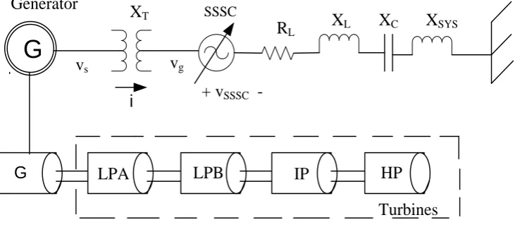
[image:2.595.131.497.546.707.2]2. IEEE First Benchmark Model with SSSC Controller
Figure 1shows the single-line diagram of IEEE first benchmark model with an SSSC installed downstream the step-up transformer located at the output of the power station. The generated voltage is denoted by vs and the
grid current is denoted by i respectively. The SSSC is modelled as a controlled ideal voltage source. The in-jected voltage is denoted by vSSSC. In classical control scheme the principle of the SSR mitigation is to replace the fundamental frequency voltage created by (at least a portion of) the inserted fixed capacitor banks by inject-ing an equal voltage that has been produced by the SSSC. As the capacitive reactance from the capacitor bank is eliminated (or reduced), the electrical resonance of the system becomes shifted, thus avoiding the risk of SSR. The effectiveness of this control strategy has been described in several publications and has been proved both analytically and through real time simulations [12] [13].
G
LPA
LPB
IP
HP
G
Turbines
Generator
X
T SSSC
R
LX
LX
CX
SYSi
v
sv
g+ v
SSSC3. Sub-Synchronous Component of Voltage
To derive the subsynchronous component of the voltage at the generator terminals, consider the generic case of a synchronous generator connected to a transmission line.
The per-unit voltage at the generator terminals inαβ-plane as
( )
( )
( )
( )
( 0 ( )), , e
j t t
s s s s
vαβ =v α t + jv β t =ω t V ω +δ (1)
where Vs is the amplitude of voltage at the generator terminals at rated speed, δ is phase displacement
ω
( )
t isthe per-unit rotor Speed and ω0 is the fundamental frequency expressed in radian per second. The generator rotor oscillates around its fundamental frequency ω0, its speed can be represented by
( )
t 0 Asin( )
mtω
=ω
+ω
(2)where A is the amplitude of the oscillation and ωm is the oscillation frequency of the rotor. Substituting (2) in (1), the α-component of the output voltage can be represented as
( )
( )
( )
( )
{
(
)
( )
(
)
( )
}
, 0 0
0 0 0
sin cos
cos sin sin
2
s m s
s
s m m
v t A t V t t
AV
V t t t t t t
α ω ω ω δ
ω δ ω ω δ ω ω δ
= + +
= + + − − + + + + (3)
The derivative of the rotor angle is given by
( )
( )
0( )
d
sin
dtδ t =ω t −ω ω B= A ω ωmt B (4)
where, ωB is the base frequency in radians per second. Therefore by integrating both sides of Equation (4), we get δ0 the rotor angle in steady-state condition is derived. The rotor angle can be written as
( )
0 cos( )
B m m
t Aω t
δ δ ω
ω
= − (5)
The α and β components of the output voltage are obtained by Substituting Equation (5) in (3). The α component is obtained as:
( )
(
)
{
(
)
(
)
(
)
(
)
}
, 0 cos 0 0 0 sin 0 0 0 sin 0 0
2
s
s s m m m m
m
AV
v α t =ωV ωt+δ + ω ω ω− ω ω− t+δ + ω ω+ ω ω+ t+δ (6)
The β component of the voltage is expressed as
( )
(
)
{
(
)
(
)
(
)
(
)
}
, 0 cos 0 0 0 cos 0 0 0 cos 0 0
2
s
s s m m m m
m
AV
v β t ωV ω t δ ω ω ω ω t δ ω ω ω ω t δ
ω
= + + − − − + − + + + (7)
When a small distribution is applied to the generator rotor, the resultant voltage will be constituted by the sum of three terms; they are fundamental frequency component, sub-synchronous component of frequency and su-per-synchronous component of frequency. The component of susu-per-synchronous frequency is higher than the sub-synchronous frequency component. For super-synchronous frequency the network presents a small positive damping, thus the super synchronous voltage does not represent a risk for the power plant. Therefore super syn-chronous component of the voltage will not be taken in to account [6].
From Equations (6) and (7), the subsynchronous component of the measured voltage is given by
( )
(
)
( 0 ) 0 π2
, 0 e
2
m
j t
s
s sub m
m
AV
v t
ω ω δ
αβ ω ω
ω
− + +
= − − (8)
The grid voltage vector can be transformed in the synchronous reference plane as
( )
( )( )
0 ( )( )
( )( )
, ,
e j t dq dq
dq
s s s f s sub
v t =vαβ t −ω =v t +v t (9)
( )
( )
( )( )
(
)
0 0π 2
, , e 0 e
2
m j t
dq j t s
s sub s sub m
m
AV
v t v t
ω δ
αβ ω ω ω
ω
− + +
−
= = − − (10)
When the generator rotor oscillates around its rated speed, the voltage at the terminals can be expressed in the synchronous dq co-ordinate system as
( )
( )
( )( )
( )( )
, , ,
dq dq
dq dq
s s f s sub s sub
v t =v t +v t +v t (11)
The frequency fsub and fsup denotes the sub-synchronous and the super-synchronous component of the measured grid voltage respectively. The network presents a small positive damping for frequencies above the fundamental. Therefore, the super-synchronous component is not taken in this paper. The subsynchronous vol-tage rotates clockwise in the synchronous reference frame. Consider the generator rotor oscillates with angular frequency ωm. The dqm-plane denotes a new set of co-ordinate systems that rotates synchronously with syn-chronous voltage vector, Equation (10) can be rewritten as
( )
( )
( )( )
, , e
m m
dq j t
dq dq
s s f s sub
v t =v t +v t −ω (12)
In order to extract the sub-synchronous component from the measured signal, (11) can be rearranged so that
, dq s f
v and v( )s sub,dq become isolated and then applying low-pass filtering on the resulting expression, the estimation control system (ECS) can be expressed as follows.
( )
( )
( )
( )
( ), , e
m j t
dq dq dq
s f f s s sub
v t =H p v t −v t ω (13)
( )
( )
( )
( )( )
( ), e , e
m m
m m j t j t
dq dq dq dq
s sub sub s s f
v t =H p v t ω −v t ω (14)
where indicated with p, the operator d ,
( )
dt Hf p
, and Hsub
( )
p represents the transfer function of a lowpass filter (LPF) for the fundamental and for the subsynchronous component, respectively. Equation (14) can be written in the synchronous dq-frame as
( )
(
)
( )
( )
, ,
dq dq dq
s sub sub m s s f
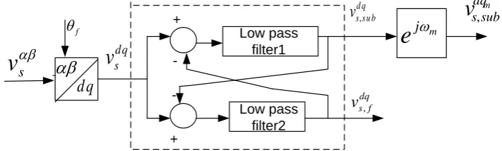
v t =H p+ jω v t −v t (15) Equations (13) and (15) can thus be combined together in order to extract the fundamental and the subsyn-chronous components of the measured voltage. Figure 2 shows the block diagram of the LPF-based estimation of subsynchronous components.
4. Subsynchronous Controller
Consider the generator is modeled as an ideal voltage source behind the sub-transient inductance of the genera-tor. To make the subsynchronous current to zero, the objective of the common control system is to produce and inject the subsynchronous component of the internal bus current/voltage by STATCOM/SSSC [9] [12]. Assume that the voltage downstream of the SSSC is equal to zero, i.e., the voltage drop over the impedance downstream the compensator is treated as a disturbance. With the signal references given in Figure 1, the law governing the sub-synchronous current controller (SSCC) can be written in the Laplace domain as
m dq sub s
v
,αβ
d q
fθ
αβ
sv
v
sdq [image:4.595.133.496.591.700.2]+ -+ Low pass filter1 Low pass filter2 d q su b s
v
, dq f sv
, mj
e
ω
( )
( )
( )
(
)(
)
( )( )
( )( )
( )( )
, SCCC
m m m i m m
sub m T sub
dq dq
p sub sub
dq dq
dq g sub
K
v s v s R j L i s K i s i s
s
ω ω ∗
= + + − + + + −
(16)
where R, LT and Lײ are the resistance of the system upstream the SSSC, the leakage inductance of the trans-former and the sub transient inductance of the generator, respectively. The current reference is (dqm)*
sub
i , while
p
[image:5.595.144.483.590.703.2]K and Ki are the proportional and the integral gains of the PI-regulator, respectively.
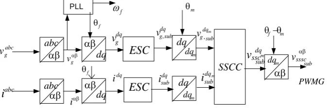
Figure 3 shows the Blok diagram of Subsynchronous controller in which the measured three-phase voltages are transformed to theαβ-plane and then to the synchronous dq-coordinate hi system by using the transforma-tion angle θf. The output of the estimation block is the fundamental and the subsynchronous voltage compo-nents, both in the synchronous dq-frame. The subsynchronous component is further transformed in the subsyn-chronous dqm-coordinate systems using the transform angle θm, obtaining by integrating oscillating frequency
m
ω . The resulting quantities are then sent to the subsynchronous component controller (SSCC). The result of SSCC is again converted into αβ and then in to. These are given to the PWM generator. From PWM generator gate pulses are taken and given to the three single phase VSC based bridges i.e. SSSC.
5. Study System Parameters
The system investigated for the study is the well-known IEEE first benchmark model. The system consists of 892.4 MVA turbine-generator connected to an infinite bus through radial series compensated line. The voltage and frequency are 539 KV and 60 Hz respectively. Program has been written to figure out turbine natural fre-quencies [2] [4]. Here five mass systems has been taken in to study, the obtained natural frequencies are 1.8002 Hz, 16.1335 Hz, 24.4785 Hz, 32.237 Hz, 47.4563 Hz. For 55% series compensation the resonant frequency is 28.14 Hz [5]. Tables 1-3 give the complete parameters of the IEEE first benchmark model with transmission line.
Rating of SSSC
In this paper three-phase VSC based bridge is used for SSSC. The amount of power needed for mitigation of SSR is related to several factors (such as series-compensation level, fault duration and its location) that cannot be predicted accurately. As the sub-synchronous frequency component of voltage and current is low, the rating of SSSC is low (0.1%). The voltage rating is 8 KV (either DC source or capacitor). The power rating is 12 MVA. The results are obtained for active power 0.1 pu [12]. The results are shown with and without SSSC.
6. Mat Lab Simulation Circuit and Results
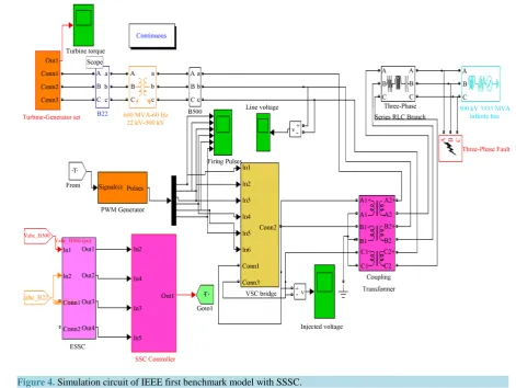
To know the effectiveness of the proposed control strategy to mitigate SSR due to Torque Amplification, the IEEE FBM with SSSC has been simulated using the Matlab-Simulink. Figure 4 shows the MAT Lab simulation circuit with the control circuit along with SSSC. The SSSC injects the voltage in series with the line according to the firing angle given by the firing angle generator. The firing angle control is obtained from the subsyn-chronous component estimation control circuit. For the value of 55% compensation, a three-phase fault is ap-plied at 1sec to the grid. The fault clearing time has been set to 0.05 s. Due to the unstable mode, when the fault is cleared, large oscillations will be experienced between the different sections of the turbine-generator shaft
f
ω
αβ g v abc g v dq gv
abci
αβ i dq i dq sub gv
, dq subi
f θ f θ PLL αβdq
αβdq
abc abc αβ αβESC
ESC
m dqdq
dq
m dqSSCC
m dq sub g v, m dq subi
αβ subv
sssc m f θ θ − m dq m θ PWMG m dq subv
ssc αβFigure 4.Simulation circuit of IEEE first benchmark model with SSSC.
Table 1. IEEE first benchmark network parameters.
Network resistance RL 0.0113 pu
Transformer reactance XT 0.142 pu
Transformation ratio 22/539 KV
Line reactance XL 0.50 pu
Transmission line reactance Xsys 0.08 pu
Table 2. Synchronous machine parameters.
Reactance Value [per unit] Time constant Value [sec]
a
X 0.130 Td′0 4.3
d
X 1.79 Td′′0 0.032
d
X′ 0.169 Tq′0 0.85
d
X′′ 0135 Tq′′0 0.05
q
X 1.71
q
X′ 0.228
q
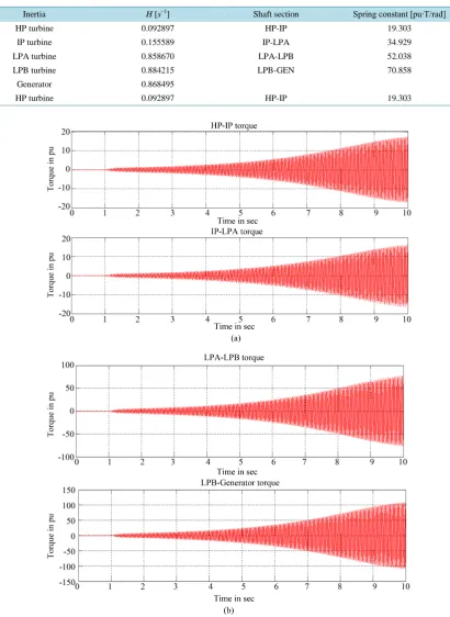
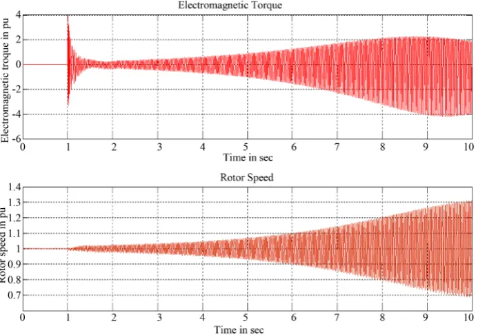
[image:6.595.86.537.547.716.2]shown in Figure 5. Figure 6shows the electromagnetic torque and rotor speed both are increasing drastically will lead to shaft damage of turbine-generator shaft.
Table 3. IEEE first benchmark shaft parameters.
Inertia H [s−1] Shaft section Spring constant [pu∙T/rad]
HP turbine 0.092897 HP-IP 19.303
IP turbine 0.155589 IP-LPA 34.929
LPA turbine 0.858670 LPA-LPB 52.038
LPB turbine 0.884215 LPB-GEN 70.858
Generator 0.868495
HP turbine 0.092897 HP-IP 19.303
To avoid the shaft damage of torque amplification effect due to SSR, SSSC is connected.Figure 7 and Fig-ure 8 shows the mitigation of SSR with series injected voltage supplied by SSSC. The voltage injected is very small shown in Figure 9. Approximately 250 Volts this is the main achievement of the proposed control system. Because of series injected voltage, the turbine oscillations are reduced to such a value which will not damage the turbine-generator shaft, thus avoiding the risk of SSR.
Figure 6. Simulated electromagnetic torque and speed for IEEE first benchmark model without
Figure 7. Simulated turbine-generator shaft torques for IEEE first benchmark model with SSSC. (a)
HP-IP and IP-LPA torques with SSSC; (b) LPA-LPB and LPB-generator torques with SSSC.
[image:9.595.127.504.419.707.2]Figure 9. Series injected voltage of SSSC during three-phase fault.
7. Conclusion
In this Research work, an accurate SSC based control scheme is proposed to mitigate the oscillations due to SSR with SSSC. The SSSC is constituted by three-phase VSC connected in series with the power line. Based on the control scheme the SSR mitigation is obtained by increasing the network damping at those frequencies which are close to the natural mode frequencies of the turbine-generator shaft. In the control scheme the estimation of subsynchronous components are proposed and are used for SSR mitigation by injecting the voltage in series with the line by SSSC. It has been shown that SSR mitigation is achieved by injecting a low amount of voltage in the grid, leading to reduced power rating for the SSSC. Finally, simulation results have shown the effective-ness of the proposed control scheme.
References
[1] Anderson, P. and Farmer, R. (1996) Series Compensation of Power Systems. PBLSH, Encinita.
[2] Anderson, P.M., Agrawal, B.L. and Ness, J.V. (1989) Subsynchronous Resonance in Power Systems. IEEE Press, New York.
[3] IEEE SSR Working Group (1985) Terms, Definitions and Symbols for Sub-Synchronous Oscillations. IEEE Transac-tions onPower Apparatus and Systems, PAS-104, 1326-1334. http://dx.doi.org/10.1109/TPAS.1985.319152
[4] Kundur, P. (1994) Power System Stability and Control. McGraw-Hill, Inc.
[5] IEEE SSR Task Force (1977) First Benchmark Model for Computer Simulation of Subsynchronous Resonance. IEEE Transactions onPower Apparatus and Systems, PAS-96, 1565-1571.
[6] Bongiorno, M., Svensson, J. and Ängquist, L. (2008) Online Estimation of Sub-Synchronous Voltage Components in Power Systems. IEEE Transactions on Power Delivery, 23, 410-418. http://dx.doi.org/10.1109/TPWRD.2007.905557 [7] Hingorani, N.G. and Gyugyi, L. (2000) Understanding FACTS. IEEE Press, Piscataway.
[8] Padiyar, K.R. and Swayam Prakash, V. (2003) Tuning and Performance Evaluation of Damping Controller for a STATCOM.International Journal of Electrical Power & Energy Systems, 25, 155-166.
http://dx.doi.org/10.1016/S0142-0615(02)00029-7
[9] Padiyar, K.R. and Prabhu, N. (2006) Design and Performance Evaluation of Sub-Synchronous Damping Controller with STATCOM. IEEE Transactions on Power Delivery, 21, 1398-1405.
Stresses Due to Torsional Oscillations in Turbine-Generator Shaft. IEEE Power Electronics Specialists Conference, 17-21 June 2007, 865-869.
[11] Perkins, B.K. and Iravani, M.R. (1997) Dynamic Modeling of a TCSC with Application to SSR Analysis. IEEE Transactions on Power Systems, 12, 1619-1625. http://dx.doi.org/10.1109/59.627867
[12] Bongiorno, M., Ängquist, L. and Svensson, J. (2008) A Novel Control Strategy for Subsynchronous Resonance Miti-gation.IEEE Transactions on Power Electronics, 23, 735-743. http://dx.doi.org/10.1109/TPEL.2007.915178
[13] Prabhu, N. Thirumalaivasan, R. and Janaki, M. (2013) Damping of SSR Using Subsyanchronous Current Suppressor with SSSC. IEEE Transactions on Power Systems, 28, 64-74. http://dx.doi.org/10.1109/TPWRS.2012.2193905 [14] J.A. Castillo J., D. Olguín S., A.R. Messina and C.A. Rivera S. (2007) Analysis and Study of Subsynchronous
Tor-sional Interaction with FACTS Devices. Electric Power Components and Systems, 35, 1233-1253.
[15] Kumar, L.S. and Ghosh, A. (1999) Modeling and Control Design of a Static Synchronous Series Compensator. IEEE Transactions on Power Delivery, 14, 1448-1453. http://dx.doi.org/10.1109/61.796239