
FAST TRANSIENT SIMULATION OF PINCETI SURGE ARRESTER MODEL ON A TRANSMISSION LINE USING ATP SOFTWARE
YUSOF BIN MUHAMAD
A project report submitted in partial fulfilment of the requirement for the award of the
Degree of the Master of Electrical Engineering
Faculty of Electrical and Electronics Engineering Universiti Tun Hussein Onn Malaysia
ABSTRACT
Lightning is one of the main causes of overvoltage on power system. Over voltages problem at the transmission line can cause flashover voltage at the insulator string, power system disturbances and transformer failure. To prevent of insulator string and equipment of the power system from damaging effect by lightning overvoltage, metal oxide surge arrester is installed at overhead line in parallel with insulator string. Due to metal oxide surge arrester have dynamic behaviour, this arrester can be simulated using non-linear resistor. Therefore Pinceti model is proposed to simulate using Alternative Transient Program (ATP) software. Several procedures have been following to calculate Pinceti arrester model parameters so that compatible with 132kV overhead transmission line system. Tested result by simulation is compared with the manufacturer arrester datasheet to evaluate accuracy of Pinceti model before installed arrester at 132kV
transmission line model. Pinceti model are installed at several locations on the transmission line model to evaluate the level of effectiveness and capabilities to reduce
ABSTRAK
Kilat merupakan salah satu punca berlakunya masalah voltan lampau dalam sistem kuasa. Masalah voltan lampau dalam talian penghantaran boleh menyebabkan berlakunya voltan lampau pada penebat, gangguan dalam sistem kuasa dan kebakaran pada alatubah. Untuk mencegah dari berlakunya kerosakan pada penebat dan alatan dalam sistem kuasa kesan dari voltan lampau kilat ini, penangkap kilat jenis metal oxide dipasang pada talian penghantaran secara selari dengan penebat. Disebabkan penangkap kilat jenis metal oxide ini mempunyai ciri-ciri dinamik, penangkap kilat ini boleh disimulasikan dengan meggunakan perintang bukan linear. Oleh itu, model penangkap kilat Pinceti dicadangkan untuk disimulasikan dengan menggunakan perisian Alternative Transient Program (ATP). Beberapa prosedur harus diikut untuk mengira parameter-parameter pada model Pinceti supaya bersesuaian dengan talian penghantaran 132kV.
Hasil ujikaji dengan menggunakan simulasi dibandingkan dengan data penangkap kilat yang diperolehi dari pembuat penangkap kilat sebenar bagi menilai ketepatan model
TABLE OF CONTENTS
TITLE i
DECLARATION ii
ACKNOWLEDGMENT iv
ABSTRACT v
ABSTRAK vi
TABLE OF CONTENTS vii
LIST OF TABLES ix
LIST OF FIGURES xi
LIST OF SYMBOLS AND ABBREVIATIONS xiv
CHAPTER 1 INTRODUCTION 1
1.1 Introduction 1
1.2 Problem statement 2
1.3 Objectives 5
1.4 Project scopes 5
1.5 Outline of dissertation 6
CHAPTER 2 LITERATURE REVIEW 7
2.1 Introduction of lightning 7
2.2 Fundamental of surge arrester 9
2.3 I-V characteristics 11
2.4 Types of surge arrester model 12
2.5 Transmission line tower 15
2.6 Lightning source 19
CHAPTER 3 RESEARCH METHODOLOGY 20
3.2 Study Alternative Transient Program (ATP) software 21
3.3 Study lightning source parameter 24
3.4 Study about Pinceti surge arrester model parameter 27 3.5 Study transmission line system model 32
3.6 Save ATP Program 39
3.7 Run ATP program 40
CHAPTER 4 RESULTS AND DISCUSSION 42
4.1. Introduction 42
4.2 Pinceti model testing 43
4.3 Install Pinceti model at transmission line 47 4.4 Discussion of the current draws to ground 60
CHAPTER 5 CONCLUSION AND RECOMENDATION 64
5.1 Conclusion 64
5.2 Recommendations 65
LIST OF TABLES
Table 3.1 Pinceti Model parameter for 20kV rating 28
Table 3.2 V-I characteristics for non-linear A0 and A1 for
V8/20µs =46.2kV 29
Table 3.3 IEC suggested for TLA rating 29
Table 3.4 ABB EXLIM P datasheet 30
Table 3.5 Pinceti Model Parameter for 120kV rating 31 Table 3.6 V-I characteristics for non-linear A0 and A1 for
V8/20µs =276kV 31
Table 3.7 Cable specification 37
Table 4.2 Calculated Residual Voltages for the ABB MWA
16kV arrester 43
Table 4.3 Voltage injected versus residual current for the
ABB MWA 16kV arrester 44
Table 4.4 Calculated residual voltages for the EXLIM P
132kV arrester 45
Table 4.5 Votage injected versus residual current for the
ABB EXLIM 120-kV arrester 45
Table 4.6 Insulator string voltage without MOV and with
MOV (left pole) 48
Table 4.7 Residual voltage and current flow to the
ground (left pole) 49
Table 4.8 Residual Voltage Without MOV and with
Table 4.9 Residual voltage and current flow to the
ground (right pole) 55
LIST OF FIGURES
Figure 1.1 Damage of transformer at TNB substation due to
lightning strike 1
Figure 1.2 No of day with lightning strike in Malaysia 3
Figure 1.3 Lightning surge arrester 5
Figure 2.1 Cloud to ground downward negative lightning 8 Figure 2.2 Porcelain housing metal oxide surge arrester 10
Figure 2.3 V-I characteristics of MO arrester 336kV 11
Figure 2.4 Pinceti Model 12
Figure 2.5 IEEE Model 13
Figure 2.6 Fernandez Model 14
Figure 2.7 132kV multi-storey transmission line 16
Figure 2.8 Insulator string 18
Figure 2.9 Time duration of a typical lightning surge 19
Figure 3.1 Main window 23
Figure 3.2 Plotting program in ATP 24
Figure 3.3 Circuit that has been used to define the parameter
of the surge model 25
Figure 3.4 Dialog box of the Hidler Type surge model 25
Figure 3.5 8/20 µs lightning waveshape 26
Figure 3.6 V-I characteristics for non-linear A0 and A1 28
Figure 3.7 Conductor phase of impedance wave 33
Figure 3.8 Shield wire of impedance wave 34
Figure 3.9 Tower surge impedance wave 35
Figure 3.11 Cable data 36
Figure 3.12 AC source 132kVL-L 38
Figure 3.13 AC source 38
Figure 3.14 VL-L probe connection 39 Figure 3.15 Save ATP program 39
Figure 3.16 Writing file name 40 Figure 3.17 ATP run 40 Figure 3.18 Select file 41 Figure 3.19 Voltage probe name 41
Figure 4.1 Residual current testing model 43
Figure 4.2 Graph Voltage Inject Versus Residual Current for 20kA rating 44
Figure 4.3 Graph voltage inject versus residual current 46
Figure 4.4 Surge at tower (back flashover) 47
Figure 4.5 Location of tower 47
Figure 4.6 Left pole upper phase (without Pinceti) 49
Figure 4.7 Left pole upper phase (with Pinceti) 50
Figure 4.8 Left Pole Medium Phase (without Pinceti) 50
Figure 4.9 Left Pole Middle Phase (with Pinceti) 51
Figure 4.10 Left Pole Lower Phase (without Pinceti) 51
Figure 4.11 Left Pole Lower Phase (with Pinceti) 52
Figure 4.12 Graph residual Voltage Versus Tower (Left Pole Upper Phase) 52 Figure 4.13 Graph residual Voltage Versus Tower (Left Pole Middle Phase) 53
Figure 4.14 Graph residual Voltage Versus Tower (Left Pole Lower Phase) 54
Figure 4.15 Right pole upper phase (without MOV) 56
Figure 4.16 Right pole upper phase (with MOV) 56
Figure 4.17 Right pole middle phase (without MOV) 57
Figure 4.19 Right pole lower phase (without MOV) 58
Figure 4.20 Right Pole Lower Phase (with MOV) 58
Figure 4.21 Graph residual Voltage Versus Tower (Right Pole Upper Phase) 59
Figure 4.22 Graph residual voltage versus tower (Right Pole Middle Phase) 59 Figure 4.23 Graph residual Voltage Versus Tower (Right Pole Lower Phase) 60
Figure 4.24 Balance lightning current to ground 61
Figure 4.25 Current flow in transmission line 62
LIST OF SYMBOLS AND ABBREVIATIONS
MOV - Metal Oxide Varistor
ZnO - Zinc Oxide
SiC - Silicone Carbaid
ATP - Alternative Transient Program
MCOV - Maximum Continuous Operating Voltage TLA - Transmission Line Surge Arrester
CFO - Critical flashover voltage
IEC - International Electrotechnical Commission IEEE - Institute of Electrical and Electronics Engineers AAAC - All Aluminium Alloy Conductor
ACSR - Aluminium Conductor Steel Reinforced TNB - Tenaga Nasional Berhad
AC - Alternating Current
CHAPTER 1
INTRODUCTION
1.1Introduction
Lightning is one of the main causes of the outages on power networks. The lightning surge can produce dangerous overvoltage, causing power supply interruptions that result in costly damage to equipment and also imposing an extra cost to the power utility because of the undelivered energy such in Figure 1.1. The amount of energy contained in a lightning stroke is very high and it can be extremely destructive, even a single stroke to a distribution line can be sufficient to cause a blackout through a feeder.
exceeds the line critical flashover voltage (CFO), flashover will occur across insulator string. This flashover issues are important for evaluating of lightning performance. Therefore, in order to increase the reliability and availability of the power system, the lightning-related outages rates must be reduced.
Nowadays, transmission line surge arresters (TLAs) are vital elements to protect the power systems against the lightning surges by absorbing the energy of surges and limiting their resultant overvoltage below a certain value which is basic impulse insulation level [1]. TLA able to reduce lightning initiated flashovers, maintain high power quality and to avoid damages and disturbances especially in areas with high soil resistivity and lightning ground flash density [2]. TLA is connected in parallel with them at selected towers. A computer program is used to determine the optimum number of locations and to calculate the arrester stresses at each of the chosen locations. Surge arrester as a robust and efficient alternative, could be located at line ends and along the line at selected points.
In Malaysia, lightning overvoltage is concern more for 132kV/275kV transmission line system. Many observations have been done to evaluate about this problem experimentally and by software modelling. One of the famous tools for modelling 132kV transmission line system is by using Alternative Transient Program (ATP) software. This software is most useful for modelling transmission line model and the most famous model design by using this software is multi-storey tower model.
1.2 Problem statement
Electrical power systems have three main parts that transform other types of energy into electrical energy and transmit this energy to consumer. The three main components are generation, transmission and distribution system. However, transmission line have the longest distance compare with generation and distribution system. So transmission line most attracted to the lightning strike due to high structure of transmission line tower.
1.2; average thunders for Kuala Lumpur are 180-300 per annum. Eighty percent of lightning discharges current to ground in Malaysia exceed 20kA, potentially approaching 50-100 million volts. Lightning is classified as a transient event. The amount of energy contained in a lightning stroke is very high. Lightning can cause destruction of equipment, damage to substation or power plant equipment.
Figure 1.2: No of day with lightning strike in Malaysia [3]
Lightning faults have two types which are flash over and back flashovers. Flash over mainly following a screen failure and caused by direct hitting to the phase conductor. Back flash over which can occur when lightning strike hits tower or the ground wire. In this case, the potential at the top of the tower rises in an important way and can exceed the dielectric strength of the insulator string. Therefore, it is very important to propose some idea for improve the lightning protection scheme in electrical power system. This can be done by proposed a new surge arrester [4].
However for the economical factor, not all transmission line towers are installed with surge arrester. As far as economy and other factors are concerned, the transmission lines in our country are only installed one or two kilometres lightning conductors in and out of the substations or power factories. Power supply faults and failure caused by detour or back lightning striking happen especially in mountain areas [6]. TNB transmission line department use TFlash Software to determine which tower and which phase should be installed with Transmission Line surge arrester (TLA).
An accurate surge arrester model will increase the lightning protective level of the electric power system. Surge arrester installation removes the superfluous charge from the line. The most common types of surge arrester are open spark gap, Silicon Carbaid (SiC) arrester with spark gap and metal oxide surge arrester without spark gap. Mainly Zink Oxide under metal oxide category is today most common used [4].
Figure 1.3: Lightning surge arrester
1.3 Objectives
The purpose of the research is to accomplish three objectives as follow:-
a) To develop 132kV high voltage transmission line system using ATP software. b) To use Pinceti surge arrester model in ATP software.
c) To evaluate the effectiveness of the Pinceti surge arrester model.
1.4 Project scopes
As the research a boundary, several limitations has describes as follow:-
1. This project only concern on Pinceti surge arrester lightning protection model performance.
2. Develop the 132kV overhead transmission line double circuit Bergeron model. 3. Develop the 10kA lightning current impulse 8/20µs wave shape and strike only at
4. Pinceti model surge arrester are installed at third, fourth and fifth tower 5. Study only metal oxide surge arrester type only.
1.5 Outline of dissertation
This thesis is dividing into five chapters. Basically, some theory and literature review, introduction, methodology, simulation result, comparison of result, analysis and discussion and conclusion were included in these five chapters.
Chapter 1 summarizes project background and elaborates on project objectives, scope and problem statement.
Chapter 2 explains a few literature reviews about surge arrester, description of lightning strike phenomenon and parameter of transmission line tower.
Chapter 3 describes the methodology of project development. This chapter also will explain detail about ATP software, 132kV transmission line tower model parameter, overvoltage cable, Pinceti surge arrester model parameter and AC voltage source. Chapter 4 shows about the result and discussion of simulation to evaluate effectiveness of Pinceti model surge arrester when installed at transmission line after 10kA lightning surge strikes at transmission line tower. This chapter divided to three phases. First phase is to shows the result of testing the effectiveness of Pinceti arrester itself. Second phase is shows the measurement result for the value of voltage and current when lightning strike to tower without Pinceti arrester and for the last phase is to shows the measurement result for the value of voltage and current at transmission line with Pinceti arrester installed parallel with insulator string. All result for those three phases are discussed briefly in this chapter.
CHAPTER 2
LITERATURE REVIEW
2.1 Introduction of lightning
Lightning is the most frequent cause of overvoltage and is classified as a transient overvoltage event. This is because lightning strikes a power line, it is like closing a big switch between a large current source and the power line circuit and cause abrupt change in the circuit conditions creating transient problem. Lightning spark resulting from the development of millions of volts between clouds or between a cloud and the earth. It is similar to the dielectric breakdown of a huge capacitor [1]. The voltage of a lightning stroke may start at hundreds of millions of volts between the cloud and earth. The study of lightning strokes in power lines is very important because typically, the highest structures located in high incidence lightning regions. Any structure, no matter its size, may be struck by lightning, but the probability of a structure been struck increases with its height [8]. Most lightning strikes terminate on shield wire rather than on phase wire.
.
Figure 2. 1: Cloud to ground downward negative lightning [8]
2.2 Fundamental of surge arrester
2.2.1 Metal Oxide Surge arrester (Zine oxide)
[image:21.612.162.499.362.637.2]The substitution of silicon carbide arresters with zine oxide surge arresters has brought benefits to overvoltage protection such as higher energy absorption capacity coupled with most simultaneous action by parallel arresters in the same line branch. Metal Oxide is a ceramal of zinc oxide with admixtures of other metal oxides such as bismuth, cobalt, manganese and aluminium. Metal-oxide (MO) surge arrester is very important protection device in power systems and widely used as protective devices against switching and lightning over-voltages in power systems [11]. Since there are no series gaps in metal-oxide surge arresters, the arresters continuously withstand the operating voltage applied. In order to improve performance and maximize applications of metal-oxide surge arresters, polymer housings have been used to replace porcelain housings. [11].
Figure 2.2 shows the porcelain housing TLA containing a single column of ZnO blocks, all individually extensively routine-tested during manufacture, dispersed with the necessary spacers as determined by the electrical design for the arrester. Longer arresters often require external grading or sealing ring to maintain a uniform and acceptable voltage stress along their length. Operation of such arrester without this grading ring therefore may lead to failure and invalidates our guarantees/warranties.
[image:22.612.148.507.272.460.2]2.3 V-I characteristics
Figure 2.3:V-I characteristics of MO arrester 336kV [12]
difficult. These V-I characteristics consist of three condition regions which are low voltage, rated voltage and overvoltage. For the low voltage operation, MOV is not function and leakage current about µs also draws to the ground. For the rated voltage condition, nonlinear MOV be a high resistance and current cannot flow to the ground and for the voltage applied to the MOV exceed from the their rating, non-linear resistance become low resistance and current can flow to the ground [12].
2.4 Types of surge arrester model
There are various surge arrester model were proposed nowadays such as IEEE, Pinceti, Fernandez, Schmith, Tominaga, Kim, Mardira, Popov and CIGRE model. However the most three popular model that always used for study about surge arrester nowadays as follows.
[image:23.612.153.489.405.627.2]2.4.1 Pinceti model
Figure 2.4:Pinceti Model [13]
necessary data are easily collected in datasheets, there is no need for an iterative correction of the parameters, and the model’s performance is accurate. The capacitance is eliminated, since its effect on model behaviour is negligible and only electrical parameters are used. The two parallel resistances are substituted for only resistance, R about 1MΩ replaced between the input terminals only to avoid numerical oscillations and nonlinear resistors A0 and A1 can be estimated by using the V-I characteristics curves that suggested by IEEE working group 3.4.11. The two non-linear resistances A0 and A1 are separated by a L1. Thus A0 and A1 are essentially in parallel and characterize the static behaviour of the Metal Oxide Surge Arrester (MOSA). For fast rising surge currents, the impedance of the filter becomes more significant, indeed the inductance L1 derives more current into the non-linear branch A0. Since A0 has a higher voltage for a given current than A1, the model generates a higher voltage between its input terminals. The important point is the criteria for choosing of the value of inductive parameters [14].
[image:24.612.160.486.423.628.2]2.4.2 IEEE model
Figure 2.5: IEEE Model [10]
estimated height of the arrester. For slow front surges, the R-L filter has very little impedance and the two non-linear sections of the model are essentially in parallel. For fast front surges, the impedance of the R-L filter becomes more significant and causes a current distributed between the two branches. This results in more current in the nonlinear section designated by A0, than in the section designated by A1. Since characteristic A0 has a higher voltage for a given current than A1, the result is that the arrester model generates a higher voltage due to high frequency current are forced by L1 inductance to flow more in the A0 resistance than in the A1 resistance. This model yields good results for arrester discharge voltages, when the discharge current has a time to crest within the range of 0.5 to 45μs. The major problem associated to it is to calculate its parameters. The IEEE Working Group suggests an iterative method, where adjustments are necessary to achieve better results. The initial parameters can be obtained through formulas that take into account both the electrical data (residual voltages), and the physical parameter (overall height, block diameter, columns number) [14].
[image:25.612.157.492.444.624.2]2.4.3 Fernandez-Diaz
Figure 2.6: Fernandez Model [15]
non-linear resistor A0 and A1 are connected in parallel and separated by inductance, L1. Capacitance, C is the value of terminal to terminal of capacitor and the resistor represent of arrester which has the value of the whole resist. The capacitance, C represents the external capacitance associated to the height of the arrester. The inductance L1, has the most influence on the result and a formula. L1 should be adjusted by a try and error procedure to match the residual voltages for lightning discharge current published in manufacturer’s catalogue. The resistor R0 is used to avoid numerical oscillations when running the model with digital program [15].
2.5 Transmission line tower
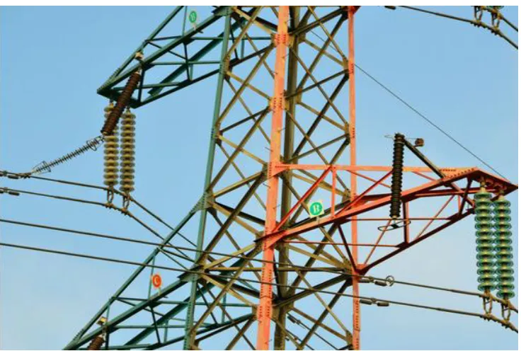
Transmission line system is one of the important things to be modelling in order to test the effectiveness of surge arrester. So, transmission line system consists of right cable parameter and transmission line tower parameter. The representation of transmission line can be modelled by using ATP software. This software offers some transmission line system model such as Bergeron, PI, J. Marti, Noda and Semlyen. The most commonly used transmission line model in Malaysia is Bergeron model because this model considers all transmission line tower parameter such as cross-arm, insulator string, tower surge impedance and footing resistance. This model basically is based on distributed LC-parameter travelling wave line model with lumped resistance. This time-domain Bergeron model is commonly used in power system transient fault analysis (Bin Li et al, APPEEC 2009). Figure 2.7 shows an actual Bergeron model for 132kV transmission line in Malaysia [9]. This Bergeron transmission line tower model type called double circuit multi-storeys model. To represent a real transmission line tower, several parameters should be considered for modelling such as cross arm, insulator string and tower surge impedance. Bergeron Model accurately represents only fundamental frequency (50Hz). There for the surge impedance is constant.
Japanese Guideline of insulation design/coordination against lightning (Takamitsu Ito et al., IEEE, 2003). This model is widely used for lightning surge analysis in Malaysia.
2.5.1 Cross arm
Cross-arms are used as transmission-line supports for 132kV and 275kV tower. In ATP software, transmission line cross arm are represented by distributed constant line branched at junction point. Their surge impedance given by:
𝑍𝐴𝐾 = 60 ln(2ℎ/𝑟𝐴) (2.1)
Where h is cross-arm height (m) rA is cross-arm radius (m2)
2.5.2 Tower surge impedance
Calculation for tower surge impedance parameter of both shield wire and phase conductor for cylindrical tower is approximated by:
𝑍 = 60 ln(√2 (2ℎ𝑟) − 1) (2.2)
Where h is tower height (m) rA is tower radius (m2)
2.5.3 Tower footing resistance
Tower footing resistance play important role because more lower the value of tower footing resistance, the easier lightning discharge current flow to ground. A footing resistance model incorporating soil ionization effect can be approximated as follow: RT =
𝑅0
√1+(𝐼𝑔𝐼) (2.3)
Ig is limiting current to initiate sufficient soil ionization
Ig= 𝐸0𝜌
2𝜋𝑅02
(2.4)
Where 𝜌 is soil resistivity (Ωm)
E0 is soil ionization gradient (400Kv/m)
2.5.4 Insulator string
[image:29.612.190.490.367.604.2]The insulator is modelled as a stray capacitor connected in parallel with a voltage controlled switch as shown in Figure 2.8. The string which consists of glass insulators, provides an equivalent capacitance used in the model. Insulator supports the conductor by providing mechanical support that depends on its normal operating and transient voltage.
2.6 Lightning source
[image:30.612.141.507.253.429.2]Lightning impulse current of large magnitudes will strike a tower top or overhead ground wire causing back flashover across insulator string. The type of current shape used for this model is 8/20µs 10kA. Figure 2.9 shows the typical lightning surge. The duration of the lightning stroke is usually less than a couple of hundred microsecond. The industry accepted 8 x 20 current wave shown in figure as a reasonable approximation of a lightning surge.
Figure 2.9: Time duration of a typical lightning surge [1] Current
CHAPTER 3
RESEARCH METHODOLOGY
3.1 Introduction
This chapter defines the necessary step to complete this project. This chapter describes start study of lightning characteristics, surge arrester models, transmission line cable data and ATP software. The steps diagram describes related activities to be done in each stage so ensure this project could be finished properly and successfully as planning. Below is the step of project methodology.
a) Study characteristics of lightning phenomenon
Preliminary studies about lightning have done on the previous chapter to know more about lightning characteristics. The source of information such as IEEE journal and paper, thesis and trusted web from internet.
b) Surge arrester study
The next step is study about surge arrester model such as IEEE, Schmidt, Fernandez and Haddad. These models have related information with Pincetti model. When got the right Pinceti parameter, the modelling arrester can be done using ATP software easily.
c) Transmission line study
formula included shield wire, phase conductor, insulator string, cross-arm, tower surge impedance, tower footing resistance. For this step, more calculation did to get the transmission line parameter.
d) Study ATP software
Next study ATP software mean transfer all transmission line and Pinceti surge arrester model parameter to ATP software. Before arrester model is installed to transmission line tower, testing did to single arrester model first to ensure the arrester will function properly. Heidler lightning surge model was used to represent for real lightning surge.
e) Observe voltage at transmission line tower
For the last step, some comparisons did on voltage value such as between installed surge arrester and without arrester. Arrester will install between phase conductor and ground. The result will be analyzed at this step.
3.2 Study Alternative Transient Program (ATP) software
3.2.1 Introduction
The software used for modelling of the overhead transmission line system as ATP. ATP is considered the most widely used for system transient simulation. It can simulate overvoltage problem such lightning phenomena and switching problem occurring in electric power. It has been continuously developed through international contributions.
3.2.2 Operating principle of ATP
arbitrary structure can be simulated. Analysis of control systems, power electronics equipment and components with nonlinear characteristics such as arcs and corona are also possible. Symmetric or unsymmetrical disturbances are allowed, such as faults, lightning surges, or any kind of switching operations including commutation of valves. Calculation of the frequency response of phase networks is also supported [16].
For this study purpose, ATP software version 1.0 is used because this software is more user friendly compare with other software because the user can build a graphical picture of an electric circuit by selecting components from menus. ATP software has two parts which are ATP Draw and ATP Plot. ATP draw supports about 70 standard components. ATPDraw is most valuable to new users of ATP and is an excellent tool for educational purposes. The possibility of building up libraries of circuits and sub-circuits makes ATPDraw a powerful tool in transient’s analysis of electric power systems [16]. ATP plotXY used to display output such waveform of voltage, current and lightning strike. Some of the typical applications of ATP software are:
a) Lightning overvoltage studies
b) Transmission lines and cable with distributed and frequency-dependent parameter c) Elements with nonlinearities: transformers including saturation and hysteresis
arrester
d) Ordinary switches, time-dependent switches, statistical switches. e) Switching transient and fault studies
f) Statistical and systematic overvoltage studies g) Transient stability and motor start-up
The following supporting routines are available in ATP:
Line constant, cable constant and cable parameter for calculation of electrical parameters of overhead lines and cables.
Generation of frequency-dependent line model input data: JMARTI setup, BEGERON setup, SEMLYEN setup and NODA setup.
ATPDraw supports most of the frequently used components in ATP. The components as Figure 2.10 are single phase as long as nothing else is specified.
Figure 3.1: Main window
3.2.3 Plotting on ATP
Figure 3.2: Plotting program in ATP
In ATP, two most widely-used plotting programs are PLOTXY and GTPPLOT. PlotXY is a WIN32 plotting program originally designed for ATP-EMTP software. It is mainly designed to make, as easy and fast as possible for line plots in Microsoft Windows environments. It can post-process plotted curves; algebraic operation, computation of Fourier series coefficients, etc. It has an easy-to-use graphical user interface, and its 32-bit code provides very fast operation. Up to 3 PL4 or ADF files can be simultaneously held in memory for easy comparison of various data, and up to 8 curves per plots versus time or X-Y plots are allowed. It has automatic axis-scaling, can plot with two independent vertical axes, and provides easy tools for factors, offsets, and zoom support, and a graphical cursor to see values in numerical format. It also can export screen plots as Windows Metafile via win32 clipboard. Figures 3.3 and 3.4 below are examples for plotting via PLOTXY [16].
3.3 Study lightning source parameter
REFERENCES
[1] Abdulwadood, "Design Of Lightning Arresters For Electrical Power System Protection," Power Engineering And Electrical Engineering, vol. 11, no. 6, pp. 433-442, 2013.
[2] S. B. e. al, "Analysis Of Lightning Protection With Transmission Line Arrester Using ATP/EMTP: Case On HV 220kV Double Circuit Line," UPEC, pp. 1-6, 2010.
[3] M. M. S. department, "Number Of Days With Thunderstorm In Malaysia".
[4] Meister, "Comparison Of Metal Oxide Surge Arrester Models In Overvoltage Studies," International Journal Of Engineering, Science And Technology, vol. 3, no. 11, pp. 35-45, 2011.
[5] Munukutla, "A Practical Evaluation Of Surge Arrester Placement," IEEE Transactions On Power Delivery, vol. 25, no. 3, pp. 1742-1748, 2010.
[6] Hailiang, "Automatic Simulation Of Transmission Line Backflashover Rate Base On ATP," pp. 1211-1215, 2008.
Distribution, vol. 8, no. 2, pp. 193-203, 2013.
[9] N. H. A. h. e. al, "Analysis Of Arrester Energy For 132kv Overhead Transmission Line Due To Back Flashover And Sheilding Failure," in IEEE International Conference On Power And Energy, Kota Kinabalu Sabah, malaysia, 2012.
[10] I. W. G. 3.4.11, "Modeling Of Metal Oxide Surge Arresters," Transactions On Power Delivery, vol. 7, no. 1, pp. 302-309, 1992.
[11] Jinliang, "Potential Distribution Analysis Of Suspended-Type Metal-Oxide Surge Arresters," IEEE Transactions On Power Delivery, vol. 18, no. 4, pp. 1214-1220, 2003.
[12] V. Hinrichsen, "Metal-Oxide Surge Arrester Fundamental," Siemens AG Power Transmission And Distribution High Voltage Division, Berlin, Germany, 2001. [13] P. Pinceti, "A Simplified Model For Zinc Oxide Surge Arresters," IEEE
Transactions on Power Delivery, vol. 14, no. 2, pp. 393-398, 1999.
[14] I. W. G. 3.4.11, "Modeling Of Metal Oxide Surge Arresters," Transactions on Power Delivery, vol. 7, no. 1, pp. 302-309, 1992.
[15] Fernandez, "Metal-Oxide Surge Arrester Model For Fast Transient Simulations". [16] L. P. e. al, Atpdraw For Windows User Manual, Norway: SINTEF Energy
Research, 1998.
[17] "Modeling Overhead Transmission Lines For Lines Arrester Study," J.A. Martinez et al.
[18] J. J. Woodworth, "Selecting Arrester MCOV And Uc Of Arrester Selection Guide," Arrester Work, 2009.
Research, 2011.
[20] C. A. C. e. al, "Simulation Of Metal Oxide Surge Arresters Behaviour," IEEE, National Technical University of Athens, Greece, 2008.
![Figure 1.2: No of day with lightning strike in Malaysia [3]](https://thumb-us.123doks.com/thumbv2/123dok_us/8764788.895840/14.612.161.496.181.343/figure-day-lightning-strike-malaysia.webp)
![Figure 2. 1: Cloud to ground downward negative lightning [8]](https://thumb-us.123doks.com/thumbv2/123dok_us/8764788.895840/19.612.141.514.75.254/figure-cloud-ground-downward-negative-lightning.webp)
![Figure 2.2: Porcelain housing metal oxide surge arrester [12]](https://thumb-us.123doks.com/thumbv2/123dok_us/8764788.895840/21.612.162.499.362.637/figure-porcelain-housing-metal-oxide-surge-arrester.webp)
![Figure 2.3:V-I characteristics of MO arrester 336kV [12]](https://thumb-us.123doks.com/thumbv2/123dok_us/8764788.895840/22.612.148.507.272.460/figure-v-i-characteristics-of-mo-arrester-kv.webp)
![Figure 2.4:Pinceti Model [13]](https://thumb-us.123doks.com/thumbv2/123dok_us/8764788.895840/23.612.153.489.405.627/figure-pinceti-model.webp)
![Figure 2.5: IEEE Model [10]](https://thumb-us.123doks.com/thumbv2/123dok_us/8764788.895840/24.612.160.486.423.628/figure-ieee-model.webp)
![Figure 2.6: Fernandez Model [15]](https://thumb-us.123doks.com/thumbv2/123dok_us/8764788.895840/25.612.157.492.444.624/figure-fernandez-model.webp)
![Figure 2.7:132kV multi-storey transmission line [9]](https://thumb-us.123doks.com/thumbv2/123dok_us/8764788.895840/27.612.160.490.138.595/figure-kv-multi-storey-transmission-line.webp)
![Figure 2.8: Insulator string [9]](https://thumb-us.123doks.com/thumbv2/123dok_us/8764788.895840/29.612.190.490.367.604/figure-insulator-string.webp)
![2 Oxo 2,3 dihydro 1H imidazo[1,2 a]pyridinium iodide](data:image/gif;base64,R0lGODlhAQABAIAAAP///wAAACH5BAEAAAAALAAAAAABAAEAAAICRAEAOw==)