International Journal of Emerging Technology and Advanced Engineering
Website: www.ijetae.com (ISSN 2250-2459, Volume 2, Issue 7, July 2012)152
Semi-Automatic Rain Wiper System
Tapan S Kulkarni
1, Harsh S Holalad
21Dept of Automobile Engg, B V Bhoomaraddi College of Engg & Tech Hubli 2
Dept of Electrical and Electronics Engg, B V Bhoomaraddi College of Engg & Tech Hubli
Abstract—The paper deals with a simple design of a Semi-
Automatic Rain Wiper System. The system is semi automatic because it has to be actuated for the first time. The system is developed using 8051 microcontroller. The principle revolves around the rate of flow of water in a cup. Corresponding to the rate of flow of water and the volume of the water, three levels of wiper speeds have been achieved.
Keywords—Cup sensor, microcontroller 8051 & Analog to
digital converter
I. INTRODUCTION
A windscreen wiper or windshield wiper is a device used to remove rain and debris from a windscreen. Almost all motor vehicle, including trains, aircraft and watercraft, are equipped with such wipers, which are usually an essential requirement.
A wiper generally consists of an arm, pivoting at one end and with a long rubber blade attached to the other. The blade is swung back and forth over the glass, pushing water from its surface. The speed is normally adjustable, with several continuous speeds and often one or more "intermittent" settings. Most automobiles use two synchronized radial type arms.
It takes a lot of force to accelerate the wiper blades back and forth across the windshield so quickly. In order to generate this type of force, a worm gear is used on the output of a small electric motor.
The worm gear reduction can multiply the torque of the motor by about 50 times, while slowing the output speed of the electric motor by 50 times as well. The output of the gear reduction operates a linkage that moves the wipers back and forth.
Inside the motor/gear assembly is an electronic circuit that senses when the wipers are in their down position. The circuit maintains power to the wipers until they are parked at the bottom of the windshield, and then cuts the power to the motor. This circuit also parks the wipers between wipes when they are on their intermittent setting.
A. Automatic Wiper system:
Vehicles are now available with driver-programmable intelligent (automatic) windscreen wipers that detect the presence and amount of rain using a rain sensor.
The sensor Automatically adjusts the speed of the blades according to the amount of rain detected.
Rain-sensing windscreen wipers appeared on various models in the late 20th century, one of the first being Nissan's 200SX/Silvia. As of early 2006, rain-sensing wipers are optional or standard on all Cadillacs and most Volkswagen, and are available on many other main-stream manufacturers.
B. Why Automatic Wiper?
In the present automobiles the number of facilities is much higher. The driver has to concentrate on road while driving, and with increased traffic, things get frustrating. The features in the car like GPRS to trace the route, music system, air condition system etc may drive away the attention of the driver. Thus an effort has been made to reduce the effort put by driver in controlling the speed of the wiper and put more concentration on his driving.
Since this system is put into use in many higher end cars and has been successfully working, an effort was made to reduce the cost of the system so that this system can be implemented in common economic cars where a common man can also enjoy the benefits.
In section II, the detail explanation about designing aspects of the system is given. In section III the working procedure of the system is given. The section IV covers the calculations involved, algorithm and the supporting graphs. The Conclusion is drawn in Section V.
II. DESIGN
International Journal of Emerging Technology and Advanced Engineering
Website: www.ijetae.com (ISSN 2250-2459, Volume 2, Issue 7, July 2012) [image:2.612.50.296.130.380.2]153
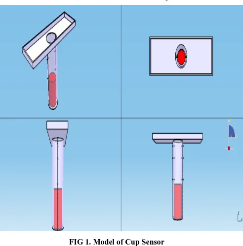
FIG 1. Model of Cup Sensor
The red cylinder inside the cylindrical cup is the floater. The tray on the top of the cup gathers the rain water.
Dimensions of the cup:
1. Radius of the cup: 2 cm 2. Height of the cup: 16 cm 3. Radius of the floater: 1.5 cm 4. Height of the floater: 8 cm 5. Height of the cup : 9 cm 6. The length of tray: 20 cm 7. Width of tray: 6 cm
TABLE I
Comparision of innovative and conventional system
SL. NO
Innovative system Conventional Automatic system
1. Sensor used consists of probes, and the circuits are completed by the rain water to start the wiper.
Sensor used here are infra red sensors which senses the moisture deposition on it.
2. The sensing device is placed inside the front hood of the car thus does not ruin the aesthetic looks of the vehicle.
The sensor is attached to the glass which is visible to all about the presence of automatic wiper system.
3. The cost of replacement of sensor is less.
The cost of the sensor is high. And the new device might not be compatible with the old system
When the rain begins and the visibility to the driver is reducing, the system has to trigger the wiper to wipe the water on the screen. It can so happen that the driver feels the need of wiper but because the floater has not reached the level of the probe the system may not begin its function. Thus certain conditions were considered and the calculations were carried out for the placement of the probes at appropriate heights. Also there is a small opening at the bottom of the cup which eventually drains water from the cup. If the rate of filling is greater than rate of discharge of rain water than the water level rises to the next
[image:2.612.324.558.426.559.2]probe level and hence the wiper speed increases.
FIG 2. The water collected at the bottom in a cup type rain sensor
Assume the thickness of the droplet to be 1mm.
Case 1: when 10% of the screen is filled with water. (10÷100)× 50× 20 ×0.1 = 10 cm3
The volume of the cone is given by the equation; Volume = = 10 cm3
10
=3.14*
r = 1.5 cm h = 1.5 cm
International Journal of Emerging Technology and Advanced Engineering
Website: www.ijetae.com (ISSN 2250-2459, Volume 2, Issue 7, July 2012)154 Case 2: when 40% of the screen is filled.
(40÷100)× 50× 20 ×0.1 = 40 cm3 40=
r =1.5cm h=5.6cm
Case 3: when 60% of the screen is filled (60÷100)× 50× 20 ×0.1 = 60 cm3
60=
r=1.5 cm h=8.5 cm where,
r is radius of the cup
[image:3.612.45.306.315.677.2]h is height of the probes head of the floater when it is at the initial position
FIG 3. The position of the probes in the cup.
TABLE II Position of probes
Height of first probe 1.5 cm
Height of second probe 5.6 cm
Height of third probe 8.5 cm
III. WORKING
FIG 4. Block diagram of working procedure of Automatic Wiper System
Rainfall water is collected in the device. As the water level increases the metallic floater moves upward. As the floater comes in contact with the first probe, the circuit is completed and the wiper begins to function at first level of speed. This flowing current’s analog value is converted into hexadecimal system by a device called analog to digital convertor. This is done because the input that is to be given to the microcontroller need to be in hexadecimal system. The microcontroller used here is 8051 microcontroller, which helps in triggering the stepper motor to rotate in the required speed and required angle. The stepper motor in turn is connected to the wiper which rubs against the screen.
As the water level increases due to increase in rain, the floater reaches the second probes and thus the speed of the wiper is increased according to the requirement. The floater used here is having a height of 8 cm so that when the floater is in contact with third level probe, the floater should also be in contact with first level of probes.
The water is discharged the drain hole at the bottom of the cup. The rate of discharge is lesser than the rate of filling of cup at moderate rain. As the rain intensity becomes high, the cup fills at greater rate. Thus there is an need to increase the rate of discharge of water too. Additional holes are present on the side walls between the probes of two different levels.
IV. CALCULATION & ALGORITHM
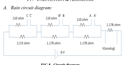
[image:3.612.317.574.462.599.2]A. Rain circuit diagram:
FIG 5. Circuit diagram
The 12V supply from the battery is scaled down to 8V by using voltage regulator.
Calculations for current flowing through different probes:
Case 1: When there is no rain
When there is no rain the circuit is not complete and thus current flows through 1K ohm resistors which are in series. R = 2.2K Ω + 1.17K Ω + 1.17K Ω = 4.54 K Ω
International Journal of Emerging Technology and Advanced Engineering
Website: www.ijetae.com (ISSN 2250-2459, Volume 2, Issue 7, July 2012)155 Case 2: When the first circuit is complete.
R = 2.44 K Ω V=2.589 V
Case 3: When the second circuit is complete. R= 1.375 K Ω
V=3.677 V
Case 4: When the third circuit is complete. R=0.305 K Ω
V=6.432 V Where,
R is resistance in ohms. V is voltage in Volts.
B. Algorithm:
Step 1. read ADC values
Step 2. if ADC value is less than 1volts , no wiper motion
Step 3. if ADC value is between 1 to 2 volts , wiper motion with speed 1
Step 4. if ADC value is between 2 to 3 volts , wiper motion with speed 2
Step 5. if ADC value is greater than 3 volts, wiper motion with speed 3.
Step 6. display rainfall intensity on LCD.
C. Speed of the wiper:
Stage1:
Stepper motor speed = 80 rpm
Angular velocity = = 8.3775 rad/s
Stage 2:
Stepper motor speed = 120 rpm Angular velocity = 12.566 rad/s
Stage 3:
Stepper motor speed =160 rpm Angular velocity = 16.755 rad/s
D. Nature of graph:
0 10 20
0 5 10
S
p
ee
d
o
f
w
ip
er
(
ra
d
/s
)
Height of the probes (cm)
Speed of the wiper (rad/s)
Speed of the wiper (rad/s)
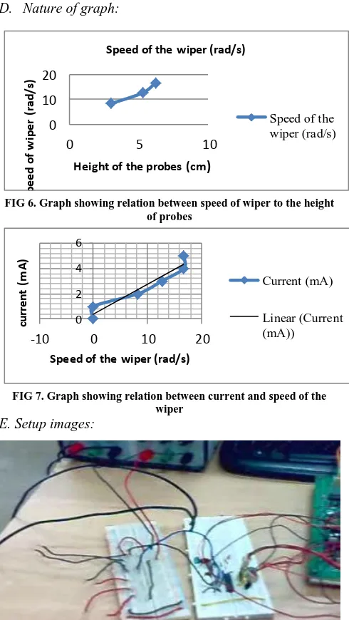
FIG 6. Graph showing relation between speed of wiper to the height of probes
0 2 4 6
-10 0 10 20
cu
rr
en
t
(m
A
)
Speed of the wiper (rad/s)
Current (mA)
[image:4.612.325.570.135.570.2]Linear (Current (mA))
FIG 7. Graph showing relation between current and speed of the wiper
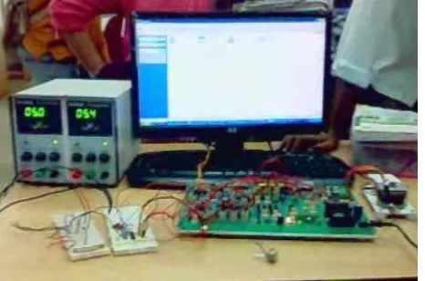
E. Setup images:
International Journal of Emerging Technology and Advanced Engineering
Website: www.ijetae.com (ISSN 2250-2459, Volume 2, Issue 7, July 2012) [image:5.612.49.282.135.289.2]156
FIG 9. Complete setup
V.
C
ONCLUSIONThe tabletop model of semi-automatic rain wiper system has worked successfully at three different stages of rain intensities. Also the cost of semi-automatic rain wiper system is INR 1080 only which can be easily implemented in all the present economic class vehicles. The cup sensor is placed under the hood and thus does not affect the aesthetic of the vehicle.
REFERENCES
[1 ] Muhammad Ali Mazidi, Janice Gillispie Mazidi & Rolin D. McKinlay ,The 8051 microcontroller and embedded system ,II edition.
[2 ] Sensor Systems, Goodrich Corporation [3 ] Article Text (p. 23)1992 Mitsubishi Mirage. [4 ] N R. Khatwate, Fundamental electrical of automobile. [5 ] K M. Gupta, Automobile Engineering.