E U R 4 8 1 6 e
Alfe
¡ΒΑ
^ p · * : ' : ^
COMMISSION OF THE EUROPEAN COMMUNITIES
m
m
l i # 3
IPIl w i l t Pi
KT»
!
Μ
IRRADIATION BEHAVIOUR OF U 0
2FUEL
RODS CONTAINING GADOLINIUM OXIDE
AS CONSUMABLE POISON
W'
ííllllf » Μ
-fc W Í P ■ ™Wü «Ht '
by"»5ii'í ιí ï tí·' 'j'ti-AJS
V-ffl
!
:ΐ
R. KLERSY, A. SCHÜRENKAMPER,
O. SIMONI and K.H. SCHRADER
mmi
[RADER g , .
l l l r a í S i l l i i
1!
{UV.
rj-i l'i« ,1
filili β
Ρ
mmm ΜΜΨ
ΡΨΜ0Μ
! Variait iijaôJSMi^hStíS
This document was prepared under the sponsorship of the Commission , ¡ ! Í 2 ' ¡ . 8 ' . » 1 I allMil
11'»!
lifelillãei:·«
1:11
of the European Communities.
Ia*(fi J totn ' ΓΡχιί ''( *fï'JJ ·***a ■ j&j * *s %*« w ^ Γι·Τ^
Neither the Commission of the European Communities, its contractors
nor any person acting on then behalf: ^ WSl·».
make any warranty or representation, express or impUed, with respect to the accuracy, completeness, or usefulness of the information contained in this document, or that the use of any information, apparatus, method or process disclosed in this document may not infringe privately owned
rights;or
l u ì
assume any liability with respect to the use of, or for damages resulting from the use of any information, apparatus, method or process disclosed in this document.
i
Ulti
¡MWmmÊma
i i
mmm li
Ifi
WM
if'«p^F
;:
lrøp
?
fα
ΐ ί * Ρ * 1 β ί Ι Γ
m
ν. m-
Alili
Mli
mäqgmm.
Commission of the European Communities
Joint Nuclear Research Centre - Ispra Establishment (Italy) Luxembourg, October 1972 - 48 Pages - 24 Figures - B.Fr. 70.—
Eight U02/SS fuel pins poisoned with Gd2Os in form of molybdenum coated
microspheres have been irradiated at burn-up values of 6 500, 9 400 and 14 000 MWD/Tr/. The linear power was of about 500 W/cm and the central temperature of the fuel varied from 2 000 to 2 600" C.
Post-irradiation analysis showed that the molybdenum coated microspheres of Gd203 remain intact when the temperature of the fuel does not exceed
1 G00 °C. Above this temperature the Mo-coating is progressively destroyed which results in the reaction between U 02 and Gd203. In the experiment no
influence of burn-up on the behaviour of the microspheres could be observed.
EUR 4816 e
IRRADIATION BEHAVIOUR OF U 02 FUEL RODS CONTAINING
GADOLINIUM OXIDE AS CONSUMABLE POISON by R. KLERSY, A. SCHÜRENKÄMPER, O. SIMONI and K.H. SCHRADER
Commission of the European Communities
Joint Nuclear Research Centre - Ispra Establishment (Italy) Luxembourg, October 1972 - 48 Pages - 24 Figures - B.Fr. 70.—
Eight U02/SS fuel pins poisoned with Gd2Os in form of molybdenum coated
microspheres have been irradiated at burn-up values of 6 500, 9 400 and 14 000 MWD/Tp. The linear power was of about 500 W/cm and the central temperature of the fuel varied from 2 000 to 2 600° C.
Post-irradiation analysis showed that the molybdenum coated microspheres of Gd2Û3 remain intact when the temperature of the fuel does not exceed
1 600 °C. Above this temperature the Mo-coating is progressively destroyed which results in the reaction between U 02 and Gd203. In the experiment no
COMMISSION OF THE EUROPEAN COMMUNITIES
IRRADIATION BEHAVIOUR OF U0
2FUEL
RODS CONTAINING GADOLINIUM OXIDE
AS CONSUMABLE POISON
by
R. KLERSY, A. SCHÜRENKÄMPER, O. SIMONI and K.H. SCHRADER
1972
temperature of the fuel varied from 2 000 to 2 600° C.
Post-irradiation analysis showed t h a t the molybdenum coated microspheres of G d203 remain intact when the temperature of the fuel does not exceed
1 600° C. Above this temperature the Mo-coating is progressively destroyed which results in the reaction between U 02 and Gd203. In the experiment no
influence of burn-up on the behaviour of the microspheres could be observed.
KEYWORDS
FUEL PINS COATING URANIUM DIOXIDE IRRADIATION BURNABLE POISON RADIATION EFFECTS GADOLINIUM OXIDES BURNUP
1. INTRODUCTION 7
2. DESCRIPTION OF THE EXPERIMENT 8 2.1. Irradiation facility 8 2.2. Test section
2.3. Fuel rods 9
3. IRRADIATION 12
4. POST-IRRADIATION EXAMINATION I4 4.1. Gamma-scanning measurements 14 4.2. Fission gas release measurements 17
4.3. Dimensional measurements 21 4.4. Metallographic examination of fuel pellets. 21
5. CONCLUSION. *' 23
LIST OF TABLES
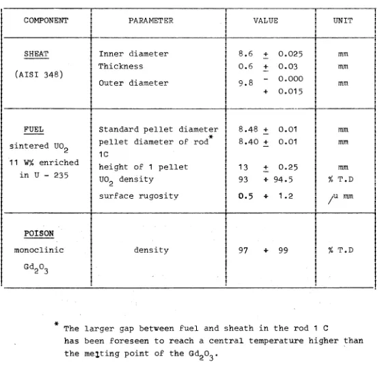
[image:8.595.74.507.41.492.2]Table 1 : Characteristics of the fuel rods
Table 2 : Poison charge in the fuel
Table 3 : Irradiation conditions
Table 4 : Irradiation times
Table 5 : Power and calculated burn-up
Table 6 : Puncture test
Gas analysis by mass-spectrometry
Table 7 : Puncture test
Isotopie composition of fission gases.
LISTE OF ILLUSTRATIONS
Fig. 1 : Section through the reactor vessel
Fig. 2 : Test section assembly
Fig. 3 : Fuel assembly
Fig. 4 : Crosssection of the fuel rod
Fig. 5 : Components of a standard fuel rod
Fig. 6 : Fuel rods 1 A and 1 Β after assembly
Fig. 7 : Poison distribution in the U02 pellets
Fig. 8 : Radial temperature distribution in the fuel
Fig. 9 : Gammascanning equipment
Fig. 10 : Gammascanning measurements, rod 1 C
Fig. 11 : Gammascanning measurements, rod 2 C
Fig. 12 : Gammascanning measurements, rod 1 A
Fig. 13 : Gammascanning measurements, rod 3 A
Fig. 14 : Typical gamma spectrum
Fig. 15 : Gamma spectrum measured on the lover end of the fuel rod 3 A
Fig. 16 : Metallographic aspect of microspheres in diffèrent radial positions of the fuel rod 1 C
Fig. 17 : Metallographic aspect of microspheres in different radial positions of the fuel rod 3 Β
Fig. 18 : Metallographic aspect of microspneres in different radial positions of the fuel rod 3 A
Fig. 19 : Macrographic and micrographie aspect of a deformed microsphere in the columnar grain zone of U0
Fig. 21 : View "of an intact microsphere near the surface of the U02 pellet
Fig. 22 : View of a microsphere located at the boundary of the columnar grain zone
Fig. 23 : Reaction between U0p and GdpO_ in different sections
of a microsphere
1. INTRODUCTION
It has been assest that the addition to reactor fuels of parasitic neutron-capturing elements in small amounts may be of great advantage for the reactor design and control. The depletion of these elements, usually designated as burnable poisons, during the reactor operation compensates for reactivity losses due to fuel depletion and accumula-tion of stable fission products.
The main advantages wich could be obtained through the use of burnable poisons are /~1_7 : extension of reactor
endu-rance, improved core performance through better flux factors, and reduced mechanical control of the reactor. The concen-tration and the geometrical shape of burnable poison must be calculated such that its consumption rate follows the fuel depletion and that no poison residue remains at the end of the reactor core life.
These requirements could be satisfied by the use of self-shielded poisons consisting of microspheres of different dia-meters wich should be burned completely at the end of the co-re life-time.
In the frame of a program sponsered by EURATOM, Fiat Nucleare and Ansaldo * for the development of a naval reactor, the use of burnable poison has been considered of particular advanta-ge, mainly for reasons of reactor control. Therefore a deve-lopment program of fuel elements containing burnable poisons has been undertaken. Fiat Nucleare has developed a technique of preparation of burnable poison consisting in microspheres of gadolinium oxide (GdpO~) coated with a thin molybdenum layer.
wich acts as diffusion barrier between U0p and GdpO,>. The
mi-crospheres are incorporated in the U0p powder and sintered
together in form of fuel pellets ¿~2_7·
-nable poison and especially the metallurgical behavior of the microspheres incorporated in the U0p fuel.
Nine fuel rods have been irradiated at a heat rating and at temperatures representative of the peak values in the naval reactor-core. The rods were assembled in three tre-foils wich reached three different burn-up values, in the range of 6.5 00 to 14.000 MWD/TU. The concentration of
bur-nable poison varied from.700 to 4.000 ppm, the diameter of the microspheres was of 300 and 500 microns. In addition some pellets contained burnable poisons in form of fine distributed powder.
2. DESCRIPTION OF THE EXPERIMENT
2.1. Irradiation facility
The test section, containing nine fuel rods, has been irradiated in the organic loop DIRCE, which is located in the central channel of the reactor ISPRA-1. The unperturbed thermal neutron flux (maximum axial) integrated between 0 and 0,58 eV is :
0n m^v = I.2.IO14 n.cm"2 . sec."1
'o max.
The schematic location of the in pile section inside the reactor channel is shown in fig. 1.
2.2. Test section
the annuii existing between the fuel rods and the fillers. The three fillers are connected through a screwed central rod, which can be operated at the head of the test section. With
this system the three fillers can be discharged separately after different irradiation time, in order to obtain three different burnups. The three upper fuel rods are instrumen ted with two CR/AI thermocouples each on the sheath. One rod is instrumented with a WRe thermocouple in the center of the fuel. A view of the fuel assembly is shown in figure 3. A mo re detailed description of the test section with the design data has been given in the irradiation proposal /~3_7·
2.3. Fuel rods
Γ
The nine fuel rods have been denominated as follows :
1 A, 2 A, 3 A upper trefoil 1 B, 2 B, 3 Β central trefoil 1 C, 2 C, 3 C lower trefoil.
The rods are similar except for the 1 A which is instru mented with a central thermocouple as shown in figure 4. Each rod consists of seven sintered U0p pellets S.S sheathed and
closed by two S.S plugs TIG welded, with air filling.
The lower pellet is thermally insulated by an Alp0~ disc; a
Nimonic 90 spring ensures the positioning of the fuel column. Figures 5 and 6 show fuel rods before and after assembly. In table 1 the main characteristic data for the fuel rods are
Table 1 Characteristics of the fuel rods
COMPONENT
S HEAT (AISI 348)
FUEL sintered UOp
11 W% enriched in U 235
POISON
monoclinic
G d2 ° 3
PARAMETER
Inner diameter Thickness
Outer diameter
Standard pellet diameter
*
pellet diameter of rod 1C
height of 1 pellet U 0o density
surface rugositv
density ■ VALUE 8.6 0.6 9.8 8.48 8.40 13 93 0.5 97 + + + + + + + 4 τ 0.025 0.03 0.000 0.015 0.01 0.01 0.25 94.5 1.2 99 t ! t t t 1 1
1
i
tl
I t tI
11
! 1j
1
t ! I1
1
I I t f t 1i
1 ti
UNIT
¡
mm j mm j mm |
1
! ! [ 1 !1
mm !
i
mm j mm j
% T.D !
!
AX mm
% T.D
■
The larger gap between fuel and sheath in the rod 1 C
The poisons have been mixed to the U0p powder in form
of powder or in form of microspheres. The microspheres, obtained with the solgel method, are coated with a 30/U molybdenum layer in a fluidised bed ¿~2_7·
The rod 1 A contains pure U0p with a central hole for
thermocouple insertion.
[image:15.595.65.561.167.802.2]The poison charge in the different fuel rods is described in table 2.
Table 2 : Poison charge
R O D
2 A 3 A 1 Β 2 Β 3 Β 1 C 2 C 3 C ! 1 t !
i
1 ! i ! t ! !I
1 t I ! I I I ! tI
1
/U spheres diameter 500 500 powder 300 300 povder 500 300 500 Gd2°3 concentration ppm 1400 2100 300 700 1200 300 4000 700 ^1400f
Fig. 7 shows the poison distribution inside the U0p pellet,
The detailed description of fuel rods fabrication and
3. IRRADIATION
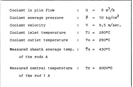
[image:16.595.86.521.263.547.2]The test section has been irradiated during 6 cycles of the reactor, under the conditions listed in table 3.
Table 3 : Irradiation conditions
Coolant in pile flow :
Coolant average pressure :
Coolant velocity : Coolant inlet temperature :
Coolant outlet temperature :
Measured sheath average temp. : of the rods A
Measured central temperature :
of the rod 1 A
G
Ρ
V
Ti TO TS Tc = = = = = = =8 m
3/h j
p J
10 kg/cm
9,5 m/sec. f
280°C !
290°C
430°C !
2000°C
Table 4 : Irradiation times
Fuel rods
Β
Irradiation time
(days) 135.2 81.9
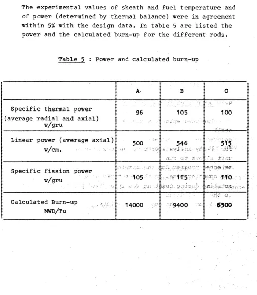
[image:17.595.100.527.132.230.2]The experimental values of sheath and fuel temperature and of power (determined by thermal balance) were in agreement within 5% with the design data. In table 5 are listed the power and the calculated burnup for the different rods.
Table 5 : Power and calculated burnup
1 !
1
! Specific thermal power j (average radial and axial) jw/gru j
Linear power (average axial)!
w/cm. j
t
Specific fission power }
w/gru j
Calculated Burnup j
M W D / T U
> ·
A
96
500
105
14000B
105546
ï"- '1 1 5
iîssxci ρ ;;r':;:*;~.
9400
C
'ir. 100 . , .515
■θ iQ.·® flBx
110
i i·» :.
•'4 J. ;s W >.
[image:17.595.58.566.252.835.2]In fig. 8 the temperature distribution inside the fuel for the different fuel rods is shown.
N.B. : The six sheath-thermocouples have worked satis-factorily for the whole irradiation period. A ve-ry good performance was also given by the central T.C. of the rod 1 A, in W-Re, which has worked for 70 days at 2.000°C, with 30 thermal cycles.
4. POST-IRRADIATION EXAMINATION
The post-irradiation examination included the following operations :
- gamma scanning of fuel elements
- determination of fission gas release
- dimensional measurements of fuel elements - metallographic investigation of fuel pellets.
4.1. Gamma-scanning measurements
The total yactivity in the energy range from about 50 KeV to 2500 KeV has been measured in steps of 0.5 mm. using a Nalcrystal.
The measurement of the y activity of some single isoto pes has been carried out in steps of 5 mm. using a GeLi
crystal. For the measurements of the rods 1 A and 3 A a steel shielding of 55 mm. thickness was placed between the fuel and the yray detector in order to lower the very high
y activity. Therefore in the following results the abso lute values of the rods 1 C and 2 C can not be compared with the absolute values obtained for the rods 1 A and 3 A. The results of the y scanning measurements are reported
in the figures 10 to 13.
The total y activity distribution is roughly representati ve for the thermal neutron flux distribution in the irradia tion facility if one is not considering the increase of the flux at the end of the fuel stacks. Fuel rod 2 C with the lowest burnup and the lowest irradiation temperature shows in some points an abrupt decrease of activity. These points correspond to the interfaces of two pellets with a dishing, which was originally present for each pellet. It cannot be:
observed for the rods 1 C, 1 A, 3 A. Temperature and. irrar; diation effects have smoothed out the activity concentra·?^ tions. In agreement with the irradiation conditions the pro files of the total activity of the rods 1 A and 3 A;are very similar. ... ■ ■ vtr*,; sti'c r.m\^s»;<?6 i¿c
Due to the relatively short irradiation time only the Ru 103 and the Zr-95 could be measured for the fuel rods 1 C and 2 C. The activity distribution seems homogeneous over the whole length of the fuel stack in the case of the rod 2 C. Fuel rod 1 C shows an increase in activity near the upper end of the fuel, where the temperature was highest. Migration of the fission products may be the rea-son for this increase.
For the rods 1 A and 3 A also the Cs 137 could be measured, due to the higher burn-up. At the bottom of the fuel stack where the neutron flux and consequently the temperature we-re highest, a higher activity of Cs in comparison with the activities of Zr-95 and Ru 103 can be observed.
4.2. Fission gas release measurements
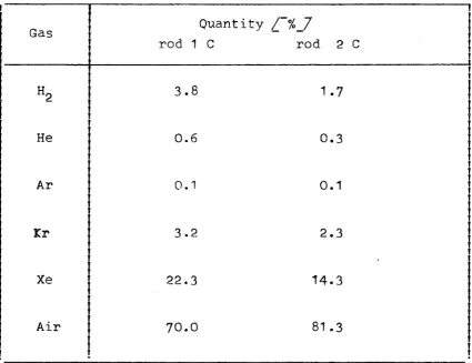
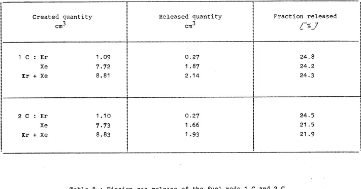
The fuel rods 1 C and 2 C have been punctered under vacuum. Using a stepwise expansion of the fission gases released from the element into the vacuum system, samples for Kr-85 measurements ( a known fraction of about 10 of the total quantity of gas ) and for mass-spectrometric analysis ( about 0.1 of the total quantity of gas ) have been prepared.
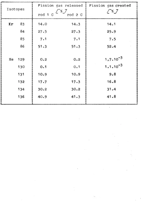
Table 6 shows the composition of the gas samples mea-sured by mass spectrometry. /~It must be mentioned, that the capsules where filled originally with air. It cannot be excluded that some air entered in the flask of the rod 2 C during preparation of the gas sample. Therefore the value of 81.3 % may be to high, but it can be assumed that this has no influence on the determination of Kr and Xe_7· The isotopie composition of the Kr and Xe of the gas samples is given in table 7. The measured values are nearly the same for the two rods. In the table there are also re-ported the theoretical compositions of the fission gases which are created during irradiation inside the fuel. There
is a good agreement between these calculated values and the observed values for the released fission gases.
Table 6 : Puncture test
Gas analysis by mass-spectrometry
1
Gas
H2
He
Ar
Kr
Xe
Air
!
1
Quantity
/~%J
rod 1 C rod 2 C
3.8 1.7
0.6 0.3
0.1 0.1
3.2 2.3
22.3 14.3
Table 7 : Puncture test. Isotopie composi-tion of fission gases
t 1 1
|
Isotopes
j Kr 83 84 85
[ 86
j Xe 129
j 130
j 131
132
134
I
136
| 1
Fission rod 1 C 14.0 27.5 7.1 51.3 0.2 0.1 10.9 17.7 30.2 40.9 gas released
/"% 7
rod 2 C
14.3 27.3 7.1 51.3 0.2 0.1 10.9 17.3 30.2 41.3
Fission gas created
Ctj
14.1
25.9 7.5
52.4
1,7.10"3
1.1.10 ô
9.8
16.8
31.4 41.8
cm3
1 C : Kr 1.09 Xe 7-72 Kr + Xe 8.81
2 C : Kr 1.10 Xe 7.73 Kr + Xe 8.83
cmJ
0,27 1.87 2.14
[image:24.842.52.763.126.499.2]0.27 1 .66 1 .93
24.8 | 24.2 j 24.3 j
r 1
t 1
24.5 i
21 .5 i
21 .9 I
IO
o
4.3. Dimensional measurements
The diameter of the fuel rods has been measured each
20 mm of length, in two angular positions. The measured
values are all included in the range between 9,79 and 9,81 mm.
From the comparison with the values before irradiation wich
varied from 9,800 mm to 9,815 mm it appears that the outer
diameter of the fuel pins did not change during irradiation.
Length measurements of the fuel pins showed no change, due
to the irradiation.
4.4. Metallographic examination of fuel pellets
The main objective of this experiment was to- investi
gate the behavior of molybdenum coated microspheres of
Gd
p0„ in contact with the U0
p, under irradiation. It is.
known that Gd
p0- reacts with U0
pat temperatures above
1.500°C forming a solid solution over the entire composi^
tion range. The molybdenum coating should act as. a diffu-.;·
sion barrier between U0
pand Gd
p0^. An extensive metallo^ °-
;graphic investigation has been made on selected fuel pel-?,
lets wich differed by the burn-up, the central temperature
-,
the concentration of Gd
p0„,. and the diameter of the micro
spheres. Pellets containing burnable poison in form of powder
were also examined.
μΐΐν
Longitudinal an transversal sections of the pellets have
been prepared. By 'successive steps of polishing- the Mo-coated
microspheres of Gd
pO_ distributed in the fuel.pellets could
be observed.
■'·
'sVl© ,·
rtaiToo eriT
assvri&d-The radial position of the observed microspheres·has been mea
sured with a low magnification optical microscopef.i rtsQirîècf.
Taking into consideration the radial temperature distribution
Eightysix section« from pellets of the fuel rods 3 A, 3 B, 1 C and 3 C have been polished and submitted to metallographic examination. A total number of about 7? microspheres could be observed in these fuel sections. Fig. 16 to 18 show the metallographic aspect of micro spheres in function of their radial position in the fuel pellets for the elements 1 C, 3 Β and 3 A. In the same
figures the radial temperature distribution is indicated, wich permits to determine for each microsphere its mean
irradiation temperature. One can observe that the micro
spheres remained intact in the temperature range below 1.500 - 1.600°C. Above this temperature the molybdenum coating is more or less destroyed and the reaction between
U0p and Gdp0~ takes place.
In most cases the spherical shape of the gadolinium oxide remains and one can assume that the self shielding effect of the poison spheres is not suppressed.
In some cases the microspheres are deformed when they are
located in the zone of the columnar grains of the U0p. It
may be that the mechanical deformation of the microspheres
due to the grain growth of the U0p contributes to the ruptu
re of the molybdenum coating.
Fig. 19 and 20 show two examples of deformed microspheres
in the zone of the columnar grains of U0p.
Fig. 21 shows an example of an intact microsphere near the surface of the U0~ pellet.
Fig. 22 shows a microsphere located at the limit of the columnar grain zone. The ondular appearence of the molybde num surface seems to indicate the beginning of a reaction between the constituents. This effect results finally in the destruction of the coating with the subsequent reaction
Fig. 23 illustrates this reaction in different sections of a microsphere. The porous zone in the different pho-tographs could be considered as the reaction boundary. At this stage of the reaction a large number of small metallic inclusions (probably Mo) can be observed in
the ceramic material. In order to illustrate the behaviour of the microspheres we have plotted in fig. 24 the total number of intact and defected microspheres in function of their irradiation temperature and of the burn-up of the fuel elements.
The influence of the temperature on the integrity of the microspheres appears very clearly in this figure, while the burn-up does not seem to have any influence.
5. CONCLUSION
The present experiment has demonstrated that the molybde-num coated microspheres of GdpO_ incorporated into U0p
pel-lets behave satisfactorily under irradiation until a tempes-rature of about 1.500 to 1.600°C. Above this tempetempes-rature the molybdenum coating is progressively destroyed wich re-sults in the reaction between the U0p and the Gdp03.
No influence of burn-up on this effect could be detected,
ACKNOWLEDGEMENTS
The authors are grateful :
to G. Abate-Daga, I. Amato and D. Martorana (Fiat Nu-cleare) for their contribution to the definition of the experiment,
to J. De Greeff, N. Mariani, R. Pagani (CCR Ispra) and M. Ravizza (Fiat Nucleare) for the preparation of the irradiation experiment,
R E F E R E N C E S
/"1_7 A. RADKOVSKY :
- Theory and application of burnable poisons.
Peaceful uses of Atomic Energy. Geneva 1958, Vol. 13.
•
/"2_7 G. ABATE-DAGA, I. AMATO, G. GRAPPIOLO :
- Nuclear fuel with burnable poison.
Part. 1 :
- GdpO microspheres preparation from
the sol-gel method. EUR 4550 e.
Part. 2 :
- Preparation and out of pile evaluation of U0p pellets Gdp0_ poisoned.
EUR 4551 e.
/~3_7 R. KLERSY, 0. SIMONI :
- DIRCE-005 - Proposta di irraggiamento di U0p contenente veleno consumabile
(Gd203).
Comunicazione Euratom n° 2493 (1970). (non available)
/"4_7 M. RAVIZZA, J. DE GREEFF, R. PAGANI, 0. SIMONI : - DIRCE-005 -Procedure di costruzione e
collaudo di nove barre combustibili con-tenenti U0p e veleno consumabile (Gd20_).
SB g g Β
τζζζζζζζζζζζζζζζζλ
~* ^ Coolant pipes
i.
v"vm
Tzzzzzzzzzm
DIRCE i n - P i l e
section
Reactor fuel Aement
Organic coolant
SHIELDING PLUG CENTRAL ROD HANGER TUBE
,S SS SS VS S g g V». VV Ά VV g g VV ■-V Π g .ν g ^ S vy S vv vv
W
,*»'.»
; · ^ • r ' . · ·.. .·
vx^\^^vv^v^^^\\x\\^^\\\\v^v^
^
.:;.^::■:;..:.:...:. "
"ΓΊ
FILLER C
STANDARO PÜKL KOD
co o
I ^v^Sz
τζζζζζζζζΖΖΖΖΖΖΖΖΖΖ
FUEL ROD 1 A
[image:34.842.38.801.54.551.2]I I I I I I I I I I I I I I
0 1 2 3
U
5 6 7 8 9 10 11. 12 13
Fig.5- Components of α standard fuel rod
1A
IB
m
2500 2000
1300 1000
500
1B-2B-3B
2C-3c""** - ^
ΣΑ^/Γ^-^Ξ^;
IA
ω co
A r (mm) Fig.7-Poison distribution inside UO, pellet
(1200 ppm, 9 = 300^0
Fig.9- Gamma-scanning équipement
A : fuel element
«J o c 3 O o .a
5 Γ
wv~v
V v V V
χ
χ " Χ Λ vχ X X X X X X
• · . · · AOO- 300- 200- 100-c o o
"^T
-1 1 1 r-Fuelr1G.l0_ROD 1C - Gamma-Scanning Measuremsnts.
Total Activity - Nal Crystal, (a ) Activity of Isotopes - Ge-Li Crystal.
c o o
υ <
5 r
t» A
o in
- 2
r-vr'
χ χ κ * * *
χ y * X * * x
. . ■
( a )
300-
200-
100-1 1 1 1
-_FueL
c O O
FtG.11_ R 0 D 2 C - Gamma - Scanning Measurments. Total Activity - Nal Crystal, (a ) Activity of Isotopes - Ge-Li Crystal.
Nimonic Spring
I
2ι
9 .
x χ
X X x X
X X
(a)
' ^ ^ ^ v ^
'V-yW' vw-v^jN*·;
200-1 150-c E IA-I ï
3 O . O
1005 0
-ky
Fu«!
l.
Fl G.12—R0D1 A -Gamma-Scanning Measurements. Total Activity - Nal C r y s t a l . ( a ) Activity of I s o t o p e s - G e - L I Crystal.
^ N i m o n i e Spring
CO
o
S 3
c
3 O
o
<
χ χ χ Χ ν
χ * Χ Χ χ
( a )
f^yAvs/^/w^-wvi
ι:
2 0 0
-
150-
ιοο5 0 -c Έ
^ m c
3 O O
t
;
l
I
Fuel,, L¿_J
FIG.13_R0D 3A-Gamma-Scanning Measurements. Total Activity - Nal Crystal.(a ) Activity of Isotopes - G e - L i Crystal
Nimonlc Sprino
A ·
3 ·
-c 3 O
o 2 · "
1'
-Nb95
Nb95
- I — : 1 Γ
ΟΟ
Oi
2500-
2000-1000
1500-4
Fuel radius (mm)
Fig: 16 Metallographie aspect of microspheres in different radial
positions of the fuel rod IC (b.up: 6500 MWD/Ty)
2500-
20ÖÖ-
7500-
7000-500
·*» •i.-V'ír'íí
>í t Vi®
&*-:·- - / V a
Λ-4 Fuel radius (mm)
Fig. 17 Metallographic aspect of microspheres in different radial
positions of the fuel rod 3B (b.up 9400 MWD/Ty)
2000-
1500-
1000-4
Fuel radius (mm)
Fig: 18 Metallographic aspect of microspheres in different radial
positions of the fuel rod 3A (b.up 14000 MWD/Ty)
50 Χ
-« . · _
128 Χ
50 Χ
. '
200 X
Fig. 20 : Macrographic and micrographie aspect of a deformed
microsphere in the columnar grain zone of U0
250 Χ
150 Χ
55 Χ
"'·'' λ YSpp^^T*^ *-^
200 Χ
Fig. 22 : View of a microsphere located at the boundary of the
columnar grain zone (burn-up 14.000 MWD/TT T, tempera
T(°C) 2 500 2 000 1500 1000 500 · · • • · · · · •
o
o
o
oo
nn
Oo
O
o
o
· · · · · · · · · · • · ·o
o°
o
o
oo
o
o
o
o
• • · · · · · · · · · • • •o·
o
0°
o
o
A K 000 Β 9 400 C 6500F i g . 2 4 - l n f l u e n c e of temperature a n d burn-up on the i n t e g r i t y of the microspheres
O I n t a c t Microsphere • Detected Microsphere
Wmmi
•v l»:"jfiïöBj
!
NOTICE TO THE READER
AU scientific and technical reports published by the Commission of the European Communities are announced in the monthly periodical
"euro-abstracts". For subscription (1 year : B.Fr. 1 025,—) or free
liiii
ill
li
ma
pili
m
u'J
SS
m
m
ty — I mea general prosperity and not individual riches — and with prosperity-disappears the greater part of the evil which is our heritage from
m
darker times.
:::::::::::::::::::::::::::::::::::::::::;::;;Γ
,«...·:<*.U .1
¡ïilllpilili»
l'¡Í:,xf :œ Lpfe|f|l«.
S A L E SOFFICES
The Office for Official Publications sells all documents published by the Commission of the European Communities at the addresses listed below, at the price given on cover.
* : » , London S.E. 1
mii
GREAT BRITAIN AND THE COMMONWEALTH
H.M. Stationery Office
liwïAiSSiïi
UNITED STATES OF AMERICA
European Community Information Service
2100 M Street, N.W. Suite 707
Washington. D.C 20 037
00198 R o m a - T e l . ( 6 ) 8 5 09
Agencies
00187 Roma - Via del Tritone 61/A e 61/Β 00187 Roma — Vla XX Settembre (Palazzo
Ministero delle finanze)
• '■■■
BELGIUM
40125 Bologna — Strada Maggiore 23/A
NETHERLANDS
N.
R
κ c
Moniteur belge — Belgisch Staatsblad Staatsdrukkerij- en uitgeversbedrijf
Christoffel Plantiinstraat uè de Louvain 40-42 — Leuvenseweg 40-42
000 Bruxelles — 1000 Brussel — Tel. 12 00 26 CCP 50-80 — Postgiro 50-80
Christoffel Plantijnstraat 's-Gravenhage — Tel. (070) Giro 425 300
8 , « , 1
Agency :
Librairie européenne — Europese Boekhandel Rue de la Loi 244 — Wetstraat 244 1040 Bruxelles — 1040 Brussel
IRELAND
GRAND DUCHY OF LUXEMBOURG
Office for official publications of the European Communities
Case postale 1003 — Luxembourg 1 and 29, rue Aldringen, Library »iC'l'jJT' T f i l ¿ 79 41 — CCP 191 -90
onery Office
¡ar's Bush in 4
Stationery ι Beggs Dublir
m
Compte courant bancaire: BIL 8-109/6003/20
Hit»! -mh-M ■
KRS
SWITZERLAND
Librairl '
6. rue 1211 ( CCP1 ¡ n W .ITÍfU. Ί ι »> I 'Si '
FRANCE
,, >?,WHÉ&ftlHrK¡
Η »»fil
Service de vente en France des publications des Communautés européennes
23 r l , Qrue Desaix Ποοοίν
75 Paris-15· - Tel. (1 ) 306.5100 ¡¿|}f £ CCP Paris 23-96
CCP Paris 23-96
!
life i"»å;#iPi^i i^ÉH
GERMANY (FR). .Γ1ί»»Τ*;Ί!».ί·,· . I L . ' Π ? " ¡ ' ' I ft,» .·, Jl ■;· ;. , « ,1
Verlag Bundesanzeiger
5 Köln 1 — Postfach 108 006 Telex : Anzeiger Bonn 08 882 595 Postcheckkonto 834 00 Köln
mimm
Librairie Payot
Grenus Genève
2-236 Genève
tit - ¡*i¿* TB
193, Bank Giro 73/4015
l l ï ï
SPAINSWEDEN
Librairie CE. Fritze
2, Fredsgatan Stockholm Post Giro
bi:
Libreria Mundi-Prensa
Castello, 37 Madrid
OUNTRIES
Ss
OTHER COUNTRIES
1 i '·« A f /, vi Æi , w ñ í H " l 3fs'L iSäi . T J H i e r TΝτ "iw' ] ¡
Seles Office for official publications of the European Communities
Tel. (0221) 21 03 48 Case postale 1003 — Luxembourg 1 Telex : Anzeiger Bonn 08 882 595 Tel. 4 79 41 — CCP 191 -90
IlllliÄie^
Compte courant bancaire; BIL 8-109/6003/200OFFICE FOR OFFICIAL PUBLICATIONS OF THE EUROPEAN COMMUNITIES Case postale 1003 —Luxembourg 1 5876
CDNA04816ENC
ft AT':»', Ι.Ϊ,Ι'. t.u^to.r.miu r* àr,mn·:\\r,uZ-J m ¿ Γ . ιί&Τ·*»·*,τβΜ*· (-(«τι«! ííam «M:!»iasail:iWl