Implementation of INS in Three Dimensional Space
using Mems based Ahrs
Himanth Yandra Gnvs Kasi V Rao K.Ravi Kumar
M.tech Student SC C, ADE, DRDO Assistant Professor Dept of ECM BANGALORE, Dept of ECM K.L.University, INDIA Karnataka, INDIA K.L.University, INDIA
ABSTRACT
Inertial Navigation System (INS) is required for implementing point to coordinate and target coordinate calculation. INS is used to update the position of Gimbal Payload Assembly (GPA) in three dimensional space.INS will provide accurate attitude, position and velocity of the system.INS shall be of light weight and shall be in small size to accommodate with in the gimbal assembly. Micro Electro Mechanical System (MEMS) based Attitude Heading Reference System (AHRS) and related processing electronics in used to meet weight and volume requirement. AHRS consists of MEMS based triaxial accelerometer, triaxial gyro, triaxial magnetometer and temperature sensor. AHRS will provide the basic information i.e acceleration & angle rates (or) delta angle & delta velocity vectors of the system. An algorthim to be developed to get the attitude and orientation of GPA in North East Down(NED) frame using Texas Instrument (TI) makes TMS320F2812 DSP Processor and AHRS. In this paper distance travelled by the system can be calculated by using MEMS based AHRS.
Keywords
Inertial Navigation System (INS), AHRS, Micro Electro Mechanical System (MEMS), Dead Reckoning.
1. INTRODUCTION
Electro optic payloads (EO) are used to perform battle field reconnaissance and surveillance missions. These tasks are effective from manned (or) unmanned aircrafts. The EO payload utilized for reconnaissance and surveillance missions, Viz., TV Camera (DLTV), Thermal Imager (FLIR) are passive in nature, which makes the system immune to counter measures/detection. High resolution monochrome /colour CCD cameras with Zoom Optics are ideal for realizing day reconnaissance and surveillance missions. For day/night missions, forward looking infrared (FLIR) system is preferred.
To maintain the Line of sight (LOS) of Payloads on the target of interest, it is necessary to steer the sensor Los to required angular position in azimuth/elevation and also provide LOS stabilization against aircraft disturbances. Gimbal Payload (GPA) is used to stabilize and steer the payload Line of sight.
Navigation is the process of pointing of a vehicle through predetermined latitudes, longitudes and determination of the body‟s position and velocity with respective to some reference coordinate frame [1]. Inertial Navigation System (INS) is the navigation sensor which uses Inertial sensors like Accelerometers and Gyroscopes. INS is completely self contained system in which accelerometers and gyroscopes are used to track the position and velocity by known the starting
point of frame. It is independent of electromagnetic radiation and the earth‟s magnetic field, are the contribution of modern technology to progress in dead reckoning navigation. INS is used to provide Position, Velocity and Orientation information like Roll, Pitch, and Yaw etc. Inertial Navigation Systems are designed for vehicles, such as ships, aircrafts, aerial vehicles etc.
GPS is another navigation system based on satellite. It is used in the unmanned Aerial Vehicle (UAV‟s), cruise missiles etc. for to compute of accurate position, velocity and time [2]. For three dimensional mode, it requires Four GPS satellite signals to compute the accurate position information. GPS performs low update rate, sensitive to jamming and it contains multipath effect. Rotational information of a system is not available. For due to this reasons, INS navigation system will be preferred for accurate attitude, position and velocity of the system.
Inertial Navigation uses inertial sensors properties to measure the state of motion of the vehicle and their changes in the positions. Dead reckoning is the modern technique used to know the current position using sensors measurements and starting position. By knowing the starting position of the vehicle advances the estimated changes in its position, speed and direction, one can keep track of the vehicle‟s current position. It automates navigation, which means keep track of position, speed and attitude continuously in all weather conditions, in space, in the sky and under the sea. Jamming of signals is not possible. INS performs high update rate, Immune to signal jamming and external noises and it also provides both rotational and translational information.
2. MEMS INERTIAL SENSORS
MEMS is a technology, it contains combination of mechanical elements, sensors, actuators, and is in a small in size where as frequency response and sensing are in wide in range [3]. It is fabricated through a process of Micro
fabrication technology. According to their sensing
3.
AHRS:
Figure (1): Represents the 3DM-GX3 AHRS
3DM-GX3-25 is a Miniature Attitude Heading Reference System (AHRS), utilizing MEMS sensor technology as shown in figure (1). AHRS consists of MEMS based tri-axial accelerometer, tri-axial gyro, tri-axial magnetometer, temperature sensors [4]. The outputs modes of AHRS contains acceleration and angle rates (or) delta angle and delta velocity and also computed orientation estimates like pitch , roll, yaw (or) Rotation matrix. Its orientation is about all axes with 360 degrees. It does not allow the common errors due to hysteresis induced by temperature changes and sensitivity to supply voltage variations [5]. For providing best performance coning and sculling errors compensated in AHRS. Advantage of the 3DM-GX3 is resistance to shock interferences of up to 500g when powered. It is the smallest and lightest AHRS and applications include inertial aiding of GPS, location tracking, unmanned vehicles, navigation etc.
4. RELATED WORK:
Objective of the project is to estimate the position of Gimbal line of sight position in three dimensional space using MEMS based IMU. The required hardware includes MEMS based AHRS, TMS320F2812 DSP based Electronics card and computer. Block diagram of the hardware setup is shown in Figure (2).
Figure (2): Block Diagram of INS
The IMU measures delta angles and delta linear velocities in the entire three dimension [6] and transfers the data to TMS320F2812 DSP through RS 232 Serial link. The IMU ensures stability of outputs against before transmitting the parameters to DSP board. The DSP implements Moving
acceleration, Bias correction on delta velocities, Filtering [7] to remove the noise present in the data received from the IMU. The processor calculates the linear displacement of the platform in three dimensional space, using the data received from the IMU.
4.1 DSP Processor :
In this project TMS320F2812 DSP processor is used. AHRS outputs of delta velocities and delta angles are transferred to the DSP Processor through the SCI communication. Functions implemented using DSP Processor are Moving Average, Bias Correction, Gravitational acceleration correction, Filtering, orientation calculation, NED frame [7]. After Processing results are transferred to PC. Its Features are JTAG Boundary scan support, High performance 32 bit CPU, Frequency of 150 MHz, it contains 56 general purpose I/O (GPIO) pins, on chip memory, two serial communication interfaces like (SCIs) and standard UART, 128 bit security key/lock,12 bit ADC, low power design and code security module (CSM). CSM function is to prevent the access on chip memory by any unauthorised persons.
These are the results executed in the MATLAB before processing to the DSP Processor. The functions of implements Moving Average, Bias Correction on delta angels, gravitational acceleration, Bias correction on delta velocities, Filtering, Distance calculation are implemented in Matlab. Raw delta velocities and delta angels outputs are shown in figure (3) & (4).
Figure (3) :Original Delta Velocities
Figure (4) :Original Delta Angels
Bias is the offset in the measurement which reduces the accuracy, performance of the system. Its values changes randomly after each turn-on. It provides two biases, turn on bias and on run bias. On run bias can be neglected. By averaging the 100 samples turn on bias can be removed. In
0 1000 2000 3000 4000 5000 6000 7000 8000 9000
-0.015 -0.01 -0.005 0 0.005 0.01 0.015
No. of sample
D
el
ta
V
el
oc
ity
X
in
m
et
er
/s
ec
original delta velocities
0 1000 2000 3000 4000 5000 6000 7000 8000 9000 -1
0 1 2 3 4 5 6 7 8x 10
-3 original delta angles
no of sample
in
ra
[image:2.595.321.542.408.589.2] [image:2.595.86.251.551.681.2]the performance of signal to noise ratio (SNR) moving average of 10 samples are considered.
Figure(5):Moving Average
Figure(6):Bias correction on delta angels
Pitch , roll, yaw calculation as shown in figure(7)
Figure(7):Pitch ,Roll, Yaw
AHRS placed at rotation stage, in the position of direction x upwards, acceleration due to that gravitational will effect on the axis. Gravitational acceleration correction in three dimensional axis before and after as shown in figure (8) and (9).
Figure(8):Before Gravitational Acceleration Correction Delta Velocities
Figure(9):After Gravitational Acceleration Correction Delta Velocities
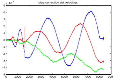
Bias correction on delta velocities as shown in figure (10)
Figure(10):Bias Correction on Delta Velocities
The high frequency noise component can be removed by using the Low Pass Filter (LPF). A Butter worth low pass digital filter of single stage with cut off frequency 1Hz is required for eliminate of high frequency components.
0 1000 2000 3000 4000 5000 6000 7000 8000 9000
-0.01 -0.008 -0.006 -0.004 -0.002 0 0.002 0.004 0.006 0.008 0.01
corrected delta velocities
D
el
ta
V
el
oc
ity
X
in
m
et
er
/s
ec
moving Averaged vel X
0 1000 2000 3000 4000 5000 6000 7000 8000 9000
-1 0 1 2 3 4 5 6 7
8x 10
-3
corrected bias delta angles x
no of sample
in
r
a
d
0 1000 2000 3000 4000 5000 6000 7000 8000 9000
-200 0 200 400 600 800 1000 1200
roll-pitch-yaw
deg
roll in deg
0 1000 2000 3000 4000 5000 6000 7000 8000 9000
-0.015 -0.01 -0.005 0 0.005 0.01 0.015 0.02
before correction
No. of sample
D
e
lt
a
V
e
lo
c
it
y
X
i
n
m
e
te
r/
s
e
c
0 1000 2000 3000 4000 5000 6000 7000 8000 9000
-2 0 2 4 6 8 10
12x 10
-3 after correction
No. of sample
D
el
ta
V
el
oc
ity
X
in
m
et
er
/s
ec
0 1000 2000 3000 4000 5000 6000 7000 8000 9000
-5 -4 -3 -2 -1 0 1 2 3 4
5x 10
[image:3.595.320.536.85.247.2] [image:3.595.59.266.103.232.2] [image:3.595.58.266.107.415.2] [image:3.595.327.527.295.424.2] [image:3.595.62.266.468.617.2] [image:3.595.335.522.489.623.2]Figure (11) : Low Pass Filter
Then components of the low frequency can be removed by using the butterworth high pass filter.
Figure (12):High Pass Filter
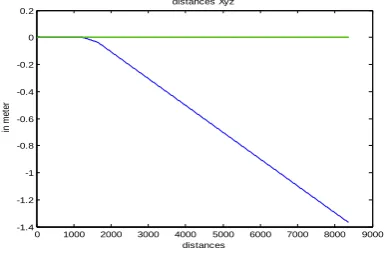
There after processing, Final Noise can be removed by using threshold process.Distance in xyz direction as shown in figure (13)
Figure(13):Travelled Distance in xyz directions
5.
IMPLEMENTATION
OF
INS
EQUATIONS
Body frame is the basic frame, x-axis is pointing towards forward direction, y-axis is pointing towards right direction and z-axis is towards down direction and orthogonal to x-y axis [8]. For NED frame, N towards north direction, E towards east direction and D towards down along the local gravity vector. Orientation matrix is needed to conversion of body frame to navigation frame.
c
bn(3x3 matrix) is the Direction cosine matrix [9], thecolumn represent unit vector in body axes projected along reference axes. For update the matrix, rotation rates are needed.
c
bn =
c
c
c
c
c
c
c
c
c
3 3 3 2 3 1 2 3 2 2 2 1 1 3 1 2 1 1Transformation from navigation to body axes is
c
c
c
c
bn
3 2 1Inversely transformation from body to reference axes is given
by
c
c
Tbn nb
cos cos cos sin sin sin cos sin sin cos sin cos cos sin cos cos sin sin sin sin cos cos sin sin sin sin cos cos cosc
bnIn this method Angular Rates and Accelerations in body frame are taken from AHRS 3DM-GX3-25. These are transformed to Navigation frame using DCM (Direction Cosine Matrix). From this DCM Euler Angles can be computed easily [10]. After transforming to Navigation frame we will get Euler angles from Angular rates and Acceleration in North, East, Down Directions .
p
dt
X
Y
q
dt
Z
r
dt
p, q, r are the angular rates in body frame. These angular values to be transformed to Navigation frame. Cbn transforms
Navigation frame to body frame [11].
M
c
M
b
bn
N;M
c
M
b T bn N Mb is the vector in body frame
MN is the vector in Navigation frame.
CbnT transforms body frame to Navigation frame
roll
pitch
yaw
C
T
X
Y
Z
Tbn T
,
,
,
,
[12]Accelerations in X, Y, Z directions are ax, ay , az .If we integrate
acceleration we will get velocity, if we integrate once again we will get distance (from Newton‟s Laws).
Distance in N,E,D frame is given by
dt
V
Dis
N
NDis
D
V
Ddt
0 1000 2000 3000 4000 5000 6000 7000 8000 9000 -5 -4 -3 -2 -1 0 1 2 3 4 5x 10
-4
filtered delta velocities
D el ta V el oc ity X in m et er /s ec
Low Pass filtered delta velocitiy X
0 1000 2000 3000 4000 5000 6000 7000 8000 9000
-2.5 -2 -1.5 -1 -0.5 0 0.5 1 1.5 2
2.5x 10
-5
No. of sample
D el ta V el oc ity X in m et er /s ec
High Pass filtered delta velocitiy X
0 1000 2000 3000 4000 5000 6000 7000 8000 9000
-1.4 -1.2 -1 -0.8 -0.6 -0.4 -0.2 0 0.2 distances in m et er distances Xyz dt
V
[image:4.595.69.275.72.199.2] [image:4.595.64.283.263.401.2] [image:4.595.68.262.474.602.2]By Using Angular rates, Angles in X,Y,Z can be calculated by a simple integration of angular rates. By Using Delta Angles, Cumulative addition of delta angle will give Angles X,Y,Z directions [13].
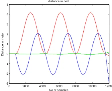
Distance in North vs East direction and Distance in NED directions as shown in figure (14)&(15).
Figure (14): North vs East distance
Figure (15): Distance in NED Directions
Similarly calculating for Y condition. AHRS placed at rotation stage, in the position of direction Y upwards, the result for North vs East direction and distance in NED directions as shown in figure(16) and figure(17).
Figure (16): North Vs East Distance
Figure (17): Distance In NED Directions
6. CONCLUSION
By using the low cost MEMS based AHRS, estimate the position of Gimbal line of sight in three dimensional motion. AHRS is used to determine the attitude and distance travelled in North East Down (NED) frame. Applications of our research include Geolocation and Geotargeting of targets using stabilized EO Payload Assemblies in Unmanned Air Vehicles. The errors in calculating position in NED frame will nullified by using online GPS Corrections.
7. ACKNOWLEDGEMENT
The author is very grateful to Shri. P.S.Krishnan, Director, ADE, DRDO, Shri AMG.Pillai Sc'F', Head, MST, Shri G.Sreenivasa Reddy Sc'F', MST division for their valuable guidance and support through out the project. The author is very thankful to Dr.S.Balaji HOD –ECM Department, Dr.K.Rajasekhar, Principal K L University, for granting permission to carry out the project in DRDO.
8. REFERENCES
[1] Sven Ronnback, “Development of a INS/GPS navigation
loop for an UAV”, Master‟s Thesis.
[2] High Precision Navigation Control with Integrated INS/GPS System IJCSNS VOL.9 No.9, September 2009
[3] A low-cost attitude heading reference system by combination of GPS and magnetometers and MEMS inertial sensors for mobile applications 2006
[4] www.microstrain.com
[5] Widyawardana Adiprawita, Development of AHRS
(Attitude and Heading Reference System)
forAutonomous UAV (Unmanned Aerial Vehicle) School of Electric Engineering and Informatics, Bandung Institute of Technology, 2007
[6] Performance Enhancement of MEMS-Based INS/GPS
Integration for Low-Cost Navigation, MARCH 2009.
[7] HVN Deepa Sikha, Implementation of Ins using
TMS320f2812 dsp processor International Journal of
Computer Applications in Engineering Sciences
(IJCAES) 2011.
[8] Strapdown inertial navigation technology by DH
Tittertondh.
[9] Inertial navigation analysis and design by O Donnell C.F
-0.05 0 0.05 0.1 0.15 0.2 0.25 0.3
-0.15 -0.1 -0.05 0 0.05 0.1
Distance North in meter
D
is
ta
nc
e
E
as
t
in
m
et
er
North Vs East Distances
0 1000 2000 3000 4000 5000 6000 7000 8000 9000
-0.15 -0.1 -0.05 0 0.05 0.1 0.15 0.2 0.25
distance in ned
No of samples
D
is
ta
n
c
e
i
n
m
e
te
r
-3 -2 -1 0 1 2 3
-0.5 0 0.5 1 1.5 2 2.5 3 3.5 4 4.5
Distance North in meter
D
is
ta
n
c
e
E
a
s
t
in
m
e
te
r
North Vs East Distances
0 2000 4000 6000 8000 10000 12000
-3 -2 -1 0 1 2 3 4 5
distance in ned
No of samples
D
is
ta
n
c
e
i
n
m
e
te
[image:5.595.329.525.77.236.2] [image:5.595.70.254.155.284.2] [image:5.595.60.270.180.462.2] [image:5.595.67.258.559.705.2][10]Inertial Navigation System by Broxmeyer
[11]Mems based integrated system by Priyanka Agarwall
[12]Inertial Navigation System Analysis by Kenneth
R.Britting
[13]Inertial Navigation and Guidance Systems by
Daniel.j.Biezad
9. AUTHORS
PROFILE
Y.HIMANTH graduated from JNTUniversity, Kakinada, currently pursing M.Tech Degree in the Department of
Electronics & Computer Enginnering in
K.L.University,Guntur. He is Presently doing M.tech Project in DRDO Bangalore.
SHRI GNVS KASI V RAO graduated from Andhra
university, completed Post graduation from Andhra
University, Vizag with Distinction. He Qualified in NET and he published four papers in various National Journals and Conferences. He is Presently Scientist „C‟ at ADE, DRDO, Bangalore. He is Presently Working in development of Electro-Optical Systems Laser Based Seekers for UAV‟S. He is Member of Indian Laser Association (ILA) and Aeronautical Society of India (AESI).
K.Ravi Kumar received the M.tech, Degree in 2009 from Andhra university, visakapatnam, Currently working as Assistant Professor in Dept. of Electronics and Computer Engineering in K.L. University, Guntur. He has 8 papers published in various National / International journals and conferences. His research areas include Security, Biometrics,