11
Virtual Cylindrical View of a Color Image for its
Permutation for an Encryption Purpose
Brahim Nini
Larbi Ben M’hidi University
Constantine Road, PO. BOX 358
04000 Oum El Bouaghi, Algeria
Darine Bouteldja
University M'hamed Bougara of Boumerdes,
Algeria
ABSTRACT
This paper presents a novel algorithm for row and column permutation of pixels for the purpose of image encryption. The algorithm introduces a virtual cylinder surrounding an image and a virtual viewer looking at it but displaced from an original position. The key idea is based on the assumption that the light ray of each pixel to the viewer in her/his original position intersects the cylinder surface at a given point. When the viewer is displaced, the new position on a perpendicular image plane on which the pixel is projected should also have its direction intersecting the cylinder on the same point. As a result, all projected pixels in the new created image are slid from their original positions; but, some of them are delayed because they are piled up or projected out. In order to avoid information loss, these pixels are projected in the created holes of the new image. The consequence of such process is the creation of the expected permutation. Despite its simplicity, the algorithm shows a strong transformation of images for the purpose of their encryption.
General Terms
Image encryption, Security, Secured transfer, Network.
Keywords
Image permutation, Image transform, nonlinear permutation, Key.
1.
INTRODUCTION
It becomes commonly known that any important data exchange through a network should be subject to a previous encryption in order to avoid a misuse by any intruder. The particular case of images and videos attracts more attention due the bulk of direct interpreted information they hold. Unfortunately, a totally secure cryptographic algorithms are difficult to build because solutions can always be found to defeat any known algorithm. One way to ensure the efficiency of a cryptographic algorithm is that it must pass the test of time and general acceptance by cryptographic communities as shown in the selection of Advanced Encryption Standard (AES) [5].
The strength of image encryption is based on the strength of the used techniques in permutation and substitution of pixels. In general, there are three major kinds of methods used for constructing secure encryption algorithms: permutation, substitution, and their combining form. The first kind is image’s pixels shuffling which makes the content hidden and confusing. The second one is the encryption of the content of each pixel.
These kinds of algorithms have been extensively addressed in the literature and many developed systems have proved their efficiency. Most of them are based on chaotic system [1, 2, 3] which is mainly used for the substitution process, although some critics are always done for an improvement purpose [9]. For the permutation process, a position permutation algorithm by magic cube transformation was for instance used in [2]. Like existing similar approaches, it is based on a transformation of magic cube's faces values. It was [8] who proposed a new method for the construction of a magic cube through consecutive improvements. Furthermore, another approach is proposed in [4] based on combinations of hybrid magic cubes which are generated from a magic square and two orthogonal Latin squares. On another hand, a cryptographic algorithm which uses Maximum Distance Separable (MDS) matrices as part of its diffusion element is proposed in [6]. Also, [7] uses matrix scrambling which is based on shifting and exchanging rule of bi-column bi-row circular queue.
In this paper, we propose a new idea of a color image pixel-permutation. It is based on a virtual cylinder having its diameter equal to the image size and centered on its axis of symmetry. It is assumed that the light ray of any pixel in the image to the viewer crosses the cylinder surface at the same point whatever the position of the viewer is. Such assumption is based on another one which considers that the current view of the image is in a plane which is perpendicular to the position of the viewer. So, based on the original image, each point is used to estimate the position the corresponding pixel takes in a target image when viewed from a different position. This may lead to a projection of the original image onto a new one where all projected pixels are slid from their original positions. What is noticeable, however, is that some pixels cannot be directly projected. They are delayed because either they occupy the same positions in the target image, or they are completely excluded from it, because the positions they take are out of its boundaries (see Figure 1). As a result, the new constructed image contains many holes where no pixel originates from the original one. The used method consists in refilling those holes by the delayed pixels to avoid information loss. The process of projection-refilling creates our expected pixel-permutation.
12 algorithm becomes more powerful. Moreover, the mixture does
not require any special changes in both algorithms.
The rest of the paper is organized as follows. The next section details the principle of a virtual cylinder. It explains the underneath mathematical basics and how the new image is generated. The third section goes more in detail to explain how the scrambling of an image is obtained. It gives the algorithms of permutation and the reverse processes. The fourth section is interested in the experimental results. It shows some obtained results, the analysis of the key and the sensitivity of the results. Finally, a conclusion is given summarizing the work and its possible extensions.
2.
VIRTUAL CYLINDER PRINCIPLE
A virtual cylinder that surrounds an image is the pillar of the idea of our pixel-permutation algorithm. It is assumed that, when looking at an image, the light ray of each pixel crosses the surface of the cylinder at a specific point. This point's position of each pixel does not change when the position of the viewer changes. Based on this assumption, and through the original image, it becomes possible to deduce any other view of the same image from another position.
[image:2.612.371.500.276.455.2]We define first the reference position in relation to the original image as having its view direction being perpendicular to the image plane and intersecting its axis of symmetry. Second, it is assumed that the viewed image from another position is on a perpendicular plane to the direction of the viewer as if the original image is rotated about the cylinder's axis. Consequently, a new image can be generated by the projection of each original pixel on its corresponding position in the new image. Note that the algorithm principle supposes that the displacement of the viewer is done along a perpendicular direction to the axis of the cylinder (see Figure 1).
Fig 1: Transformation of the original image when viewed from different positions due to the virtual cylinder.
In order to understand how the image is generated, and how the process of permutation is done, the next subsections state the mathematical basics and image projection that are the underneath of the overall process.
2.1
Mathematical Expressions of a Particular
Position of the Viewer
As stated before, it is assumed that the light ray of any pixel in the image crosses the surface of the cylinder. So, let us consider a pixel located at PPoo from the middle of the image and viewed
from the reference position situated at VVoo (see Figure 2). This
pixel has its light ray which is intersecting the cylinder at the point PP. The position in which it is viewed in the target (or generated) image depends on the new position of the viewer. So, if a viewer is at a position VVtt, the pixel is projected on the point
Pt
Pt in the new image. The objective is then to determine the
[image:2.612.57.286.451.661.2]amount of OPOPtt.
Fig 2: The system of projection that estimates the position of a pixel in the generated image.
Let the angle between the direction of the reference position and a new one be µµ. This angle is either directly known or calculated through the displacement ¡ ¡ !VoVt
¡ ¡ !
VoVt. Let also rr be the radius of the
cylinder which is the image half size. Let now ¸¸ be ®¡ µ®¡ µ for the case of figure (2). Using the 4 OP4 OPooVVoo and based on the fact that
A
A is the orthogonal projection of PP onto OVOVoo, it is easy to see
that AP = r: sinAP = r: sin¸¸, and AVAVoo= OV= OVoo¡ r: cos¸¡ r: cos¸. Moreover, the
fraction O Po
A P = O Vo
A Vo
O Po
A P = O Vo
A Vo being true, it becomes easy to obtain the
expression of OPOPoo:
OPo=
OVo:r: sin¸
OVo¡ r: cos¸
OPo=
OVo:r: sin¸
OVo¡ r: cos¸
(1)
Transformed into an equation, expression (1), where ¸¸ is the variable, becomes:
OPo: cos¸ + OVo: sin¸ =
OPo:OVo
r OPo: cos¸ + OVo: sin¸ =
OPo:OVo
r
(2)
13 cos(¸ ¡ ' ) = OVo: cos'
r cos(¸ ¡ ' ) = OVo: cos'
r (3)
where t an ' = O Po
O Vo
t an ' = O Po
O Vo.
In the same way of reflection for the establishment of expression (1), the use of 4 OP4 OPttVVtt and the fact that P BP B is perpendicular to
OVt
OVt lead to the equality O PB Pt = O VB Vt
t
O Pt
B P =
O Vt
B Vt and the expression of OPOPtt:
OPt = OV t:r: sin®
OVt¡ r: cos®
= OVo:r: sin® OVo¡ r: cos®: cosµ
OPt = OV t:r: sin®
OVt¡ r: cos®
= OVo:r: sin® OVo¡ r: cos®: cosµ
(4)
since OVOVtt = OV= OVoo=cosµ=cosµ.
As ®® is linked to ¸¸, the estimation of OPOPtt in expression (4)
depends on the solutions of equation (3). So, the value of ¸¸ which suits the described system is used to deduce the one of ®®. For this, note that the values of the three angles µµ, ¸¸, and ®®, are taken positive, and particularly, the one of µµ should be 0 < µ < ¼=2
0 < µ < ¼=2; otherwise, the image becomes no longer viewed.
Among the solutions of equation (3), the accurate is the one that fits the defined system. This means that ®® should be chosen so that its relation to ¸¸ remains always respected. It is clear that this relation depends on the position of the point PP on the cylinder. In fact, there are three cases where ®® is expressed differently (see Figure 3). So, it is important to determine in the original image the ranges that specify which expression of ®® should be used, and to select the part of the target image on which the pixel should be projected according to each expression.
® = µ+ ¸
® = µ+ ¸ ® = µ¡ ¸® = µ¡ ¸
® = ¸ ¡ µ ® = ¸ ¡ µ
Fig 3: Values of ®® depending on the position of the pixel and its image on the cylinder.
Figure (3) shows that the junctions of OVOVoo and OVOVtt with the
cylinder define the boundaries of different cases on both images. When the point of interest is the junction of OVOVoo with the
cylinder, it means that ¸ = 0¸ = 0 and ® = µ® = µ. This defines where the middle of the original image should be projected in the target one. Let us call it PPttoo (see Figure 4). In this case and according
to expression (4), OPto=
OVo:r : si nµ
O Vo¡ r : cos2µ
OPto=
OVo:r : si nµ
O Vo¡ r : cos2µ, and to find OPOPtt of any
other pixel situated on the left half of the original image, the expression ® = µ+ ¸® = µ+ ¸ is used. So, any calculated value for OPOPtt
is larger than OPOPttoo. Furthermore, the point which is the junction
of OVOVtt and the cylinder is projected in the middle of the target
image and its position in the original one is r + OPr + OPoott, where
OPot =
O Vo: r : si nµ O Vo¡ r : cos µ
OPot =
O Vo: r : si nµ
O Vo¡ r : cos µ according to expression (1). In fact, for such
point, it is clear that ¸ = µ¸ = µ. Consequently, for any pixel which is on the half right side of the original image and on the left side of OPot
OPot, the expression ® = µ¡ ¸® = µ¡ ¸ is used for the sake to
determine the value of ®® which is used in expression (4). However, in the target image, the position the pixel takes is in the left half side. Therefore, any other pixel on the right of OPOPoott
[image:3.612.384.491.329.464.2]has its target position in the half right side of the target image, and to be determined, the expression ® = ¸ ¡ µ® = ¸ ¡ µ is used.
Fig 4: Where the middle of each image is positioned in the other one.
The established expressions are all based on the fact that the viewer is situated on the right side of the reference position. One can easily verify that every expression remains true for a mirror view. This means that if the viewer is on the left side, the reflection is simply done on the symmetrical images to figures (2, 3, and 4). So, any obtained result remains valid.
2.2
New Image Generation
[image:3.612.61.283.391.695.2]14 The transformation of the original image needs then two basic
parameters. They are the side the viewer takes from the reference position (angle µµ) and her/his distance OVOVoo from the image
which is used to determine OVOVtt. They constitute the most
important parts of the permutation process key. Therefore, since the permutation is done along horizontal and vertical directions and requires two virtual cylinders, the distance OVOVtt and the
angle µµ are both formed by two components: the horizontal (OVOVooxx and µµxx) and vertical (OVOVooyy and µµyy) displacements.
In addition, there are two types of pixels which are not preliminary projected onto the new generated image (see Figure 1). The first type is constituted of lines or columns that have their projection positions out of the boundaries of the image. They are called PPou tou t. The second type includes the several lines
or columns having the same projection positions. They are so, because the evaluated positions are rounded to their nearest integers, and some of them become the same. Consequently, any given position is used for the projection of only one line/column, and the others are delayed. The latter are called PPr epr ep. Thus,
because not all lines/columns are projected, some holes appear in the new image where no information is provided from the original one.
Based on these considerations, the algorithm of initial transformation of the original image is as follows:
% Algorithm: New_Image_Gen
for each position (column/line) of the original image Evaluate the corresponding OPo;
phi = atan(OVo/OPo);
Solve equation (3) and chose the accurate value of lambda; Estimate OPt depending on the position in relation to r and r+OPto;
if OPt is a definite position in the target image
if OPt is not yet used
Copy the column/line at OPo to the position OPt in the new image
Mark OPt as used;
else
Mark OPo as repeated and add it to Prep;
end
else
Mark OPo as out and add it to Pout;
end end
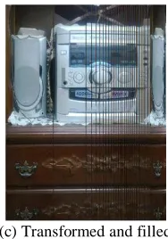
(a) Original (b) Transformed
[image:4.612.390.484.70.204.2](c) Transformed and filled
Fig 5: Application of "New_Image_Gen" algorithm on an image with OVOVoo= 1:5£ Col= 1:5£ Col and µµxx == ¼=12¼=12
3.
IMAGE CONTENT PERMUTATION
3.1
Reintroduction of Delayed Pixels
The second part of the proposed algorithm simply reintroduces the delayed lines and/or columns so that they occupy the created holes into the generated image. So, in order to understand how these pixels are reintroduced, notice three important features in the projected image. The first one is that PPou tou t are all situated on
the border of the image. They are contiguous and form a unique bloc which disappears completely in the new image. The second one is that the lines/columns that are projected on the same positions and delayed are physically dispersed. Finally, a set of dispersed and undefined lines/pixels appears on the opposite side of the viewer because this part becomes stretched.
For the reason that the reintroduction should take into account the original positions in order to separate contiguous pixels from each other, PPou tou t are introduced first. As it is clear in figure
(5(b)), the large hole is on the same side of the viewer. So, it is important not to reintroduce PPou tou t into it. This is important,
because this will be limited in a bloc exchange, which reduces the capacity of shuffling in the permutation process. For this reason, PPou tou t is introduced in the created holes of the stretched
part. This splits the bloc into separated lines or columns, and hence, reinforces the shuffling process. To do it, the algorithm begins by searching from the opposite side of the viewer for existing holes in order to paste PPou tou t into them.
For PPr epr ep, they are simply pasted into the remaining holes. Since
they are initially not close to each other, they remain dispersed whatever the positions into which they are pasted. Moreover, they are reintroduced in the new image in a reverse order from their initial one (see Figure 5(c)).
3.2
Shuffling Procedure
The target image is shuffled based on repeating the process of new image generation and reintroduction of delayed pixels several times. In fact, several repetitions of the generation of a new image based on a previously generated one are enough to get a complete ciphered image. However, knowing the basics of this algorithm, it becomes easy to reconstitute the original image just by varying and combining different values of µµ and OVOVoo. So, in
15 on which it is possible to play for the rearrangement of the target
image. The first one is to apply "New_Image_Gen" algorithm alternatively along the columns and lines directions with different values of µµ and OVOVtt,. The second one is to use for each
step of a new generation different values of µµ and OVOVtt, and
alternate between them. Finally, the third one is to apply the rearrangement to RGB colors order too. These combinations make the retrieval of the original image very difficult because of the huge number of possibilities they create.
Furthermore, the permutation of colors from their initial order is made randomly, and based on µµ and OVOVoo. The first step consists
in transforming the vector VVor deror der = [0; 1; 2; 3; 4; 5]= [0; 1; 2; 3; 4; 5] with the same
algorithm "New_Image_Gen". Then, for each pixel, the modulo of the sum of its line and column to the value 6 is calculated. The aim is to select an order in which the three colors red, green, and blue are to be reordered. For this, the following orders are used:
0: do not change the current order 1: R B G
2: G R B 3: G B R 4: B R G 5: B G R
Therefore, the value of the modulo is used as the current index in Vor der
Vor der, and its current value is used to choose the order to apply
on the colors.
The overall algorithm becomes:
Image = Original_Image;
Repeat for a given number of permutation For each direction do alternatively
% direction may be lines (dir=y) or columns (dir=x) Repeat for nbr_dir_repetition
Select theta_dir and OVo_dir of the current step; Using New_Image_Gen do
Permute color bytes;
Permute Image in the direction of dir; end
end
end end
3.3
Reconstruction of the Original Image
The reconstruction of the original image is based on a reverse process of its permutation. Knowing the used values of µµ and OVo
OVo during the first permutation, the reconstruction of the
original image follows exactly the reverse steps.
4.
KEY ANALYSIS AND EXPERIMENTAL
RESULTS
4.1
Structure of the Permutation Key
The permutation algorithm which is presented in this paper is strong enough to make the transformed image very difficult to reconstitute. In fact, the key of permutation may be as complex as it is expected. It depends on very simple values, but when combined together, they become very difficult to untie. For example, one form of the key may be [400; 3;[400; 3; ¼¼88;; 1212¼¼;; ¼¼99;;
1:5; 1:8; 1:0; 4;
1:5; 1:8; 1:0; 4; 2020¼¼;; 1515¼¼;;1919¼¼;;1111¼¼;;1:7; 1:2; 1:4; 1:9]1:7; 1:2; 1:4; 1:9] which is not so complex. It means that there will be 400 permutations, and at each one, the image is permuted 3 times along the columns using
respectively the values [[¼¼88;;1212¼¼;;¼¼99]] for µµxx, and [1:5; 1:8; 1; 3][1:5; 1:8; 1; 3] for
OVox
OVox, whereas it is permuted 4 times along the lines using the
values [[2020¼¼;;1515¼¼;;1919¼¼;;1111¼¼]] for µµyy, and [1:7; 1:2; 1:4; 1:9][1:7; 1:2; 1:4; 1:9] for OVOVooyy.
The values of OVOVooxx and OVOVooyy are multiplied respectively by
nb columns
nb columns and nb li nesnb li nes which are respectively columns and lines numbers of the image. Note that at each step, the order of each pixel’s colors in the image changes depending on its position.
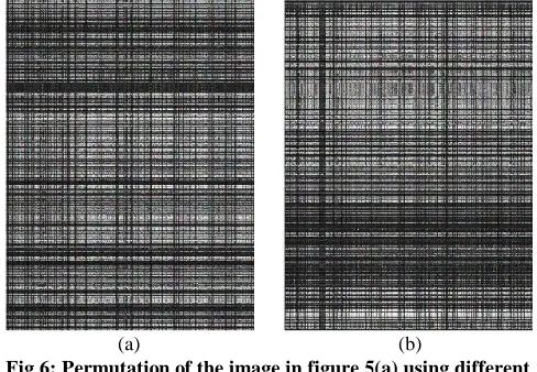
For instance, figure (6) shows the permutation of the image shown in figure (5(a)) with different parameters. The image shown in figure (6(a)) is shuffled using 200 permutations with two sub-iterations. The one shown in figure (6(b)) is shuffled using 300 permutations with also two sub iterations. What is remarkable is that the number of permutations has no great effect on the result. From the appearance point of view, both images are completely non-comprehensible. The number of iterations is important for the purpose to make the rearrangement difficult for any misuse.
[image:5.612.316.560.286.455.2](a) (b)
Fig 6: Permutation of the image in figure 5(a) using different values for the key. The values for (a) are: 200 iterations,
µx 1= 16180¼
µx 1= 16180¼, µµx 2x 2==1010180180¼¼, OVOVx 1x 1= 1:4= 1:4, OVOVx 2x 2= 1:8= 1:8, µµy 1y 1==
12180¼
12180¼, µµy 2y 2== 1717180180¼¼, OVOVy 1y 1= 1:7= 1:7, and OVOVy 2y 2= 1:1= 1:1, and the
values for (b) are: 300 iterations, µµx 1x 1== 1414180180¼¼, µµx 2x 2== 2020180180¼¼,
OVx 1= 1:4
OVx 1= 1:4, OVOVx 2x 2= 1:0= 1:0, µµy 1y 1==1515180180¼¼, µµy 2y 2==1010180180¼¼,
OVy 1= 1:0
OVy 1= 1:0, and OVOVy 2y 2= 1:5= 1:5.
4.2
Space Values of the Key
Depending on the initial values of the chosen key, the reverse process may be very sensitive. Just one value of µµ which is different from the one used in the permutation process by 0.0001 blurs the retrieved image (see Figures 7(a) and 7(b)). The retrieval of the original image is also affected by the values of OVo
OVo, however the sensitivity is about 0.001 (see Figures 7(c) and
7(d)). So, given a RGB 512512£ 512£ 512 color image, if we consider that OVOVoo varies in the interval
[0:5£ 512::2:5 £ 512] = [256::1280]
[0:5£ 512::2:5 £ 512] = [256::1280] and µµ in [pi =180::pi =4] = [0:0175::0:7854]
[pi =180::pi =4] = [0:0175::0:7854], and for a number of iterations equal to 1000, the number of possible permutations is 10250001025000
(= (1280¡ 256 + 1) £ 1000)
(= (1280¡ 256 + 1) £ 1000) £ 7680000£ 7680000 (= (7854¡ 175 + 1) £ 1000)
(= (7854¡ 175 + 1) £ 1000)¼ 7:872 £ 10¼ 7:872 £ 101212
16 increases rapidly when several sub-iterations are used. For
example, the use of just two different values for µµxx and µµyy makes
this number becoming 6:19686:1968£ 10£ 102525, because the same number
of combinations is obtained on both directions, i.e., horizontal and vertical.
The size of the key depends on the chosen intended security for the permutation. The more there are local permutations within the same step, the more the key size is bigger. However, the more the key is longer, the more the permutation becomes secure from attacks.
Moreover, together with an encryption algorithm, this permutation algorithm becomes more powerful. In fact, the reconstruction of the original image becomes almost impossible. Even though the used combinations of the different values of µµ and/or OVOVoo may be deduced, the pixels themselves should be
decrypted in order for the image to be understood. Moreover, the decryption process should substitute the correct pixels values in the correct order for the image to be viewed.
(a) (b)
[image:6.612.316.559.76.234.2](c) (d)
Fig 7: Reconstruction of the image in figure 6(b) having all values of the key equal to the original one except for (respectively from (a) to (d)): µµxx (µx 1u s ed = 14
¼
180 + 0:0001
µx 1u s ed = 14
¼
180 + 0:0001),
µy
µy (µy 1u s ed = 15
¼
180+ 0:0001
µy 1u s ed = 15
¼
180+ 0:0001), OVOVooxx
(OVOVoox 1u sedx 1u sed = 1:5 + 0:001= 1:5 + 0:001), and OVOVooyy
(VOVOy 1y 1u s edu s ed = 1:0 + 0:001= 1:0 + 0:001)
4.3
Experimental Results
(a) (b)
Fig 8: The same image used in [2] permuted using 500 iterations, µµx 1x 1= 0:3491= 0:3491, µµx 2x 2= 0:2443= 0:2443, µµy 1y 1= 0:3316= 0:3316,
µy 2= 0:2094
µy 2= 0:2094, µµy 3y 3= 0:2618= 0:2618, OVOVoox 1x 1 = 945= 945, OVOVoox 2x 2 = 1215= 1215,
OVoy 1 = 776:1
OVoy 1 = 776:1, OVOVooy 2y 2 = 1014:9= 1014:9, and OVOVooy 3y 3 = 1194= 1194.
Figure (8(b)) shows the permutation process applied on the same image (Figure 8(a)) used in [2] for an encryption purpose. The result shows that when the colors are spread out in the image, the latter becomes completely blurred without being encrypted. In addition, the histograms of the two images show that, from statistical point of view, they are significantly different. Whereas, in figure (8(b)), the obtained histograms in [2] for the encrypted image are flat, the ones obtained in our case are not, but very misguiding. Note that this result is with no encryption involved.
(a) (b) (c)
(d) (e) (f)
[image:6.612.56.296.290.605.2] [image:6.612.340.533.393.688.2]17
5.
CONCLUSION
A new algorithm of an image permutation based on a geometrical projection is presented. The algorithm is based on a virtual cylinder surrounding the image. Hence, for a viewer looking at the image from the reference position, s/he sees it as it is, and the light ray of each pixel intersects the cylinder surface at a specific point. Therefore, when the viewer looks at the image from another position, each point is projected on a new perpendicular image to her/his direction. The new position the point takes is used to permute the pixel from its original position to this one. In the resulting image, many holes are then created due to some projected positions that are outside the target image, and to the part which becomes stretched. So, the pixels which are not directly permuted are reintroduced in the created holes. This process is repeated several times so that the entire image becomes blurred. This is what creates a permuted image of the original one.
The algorithm depends heavily on the used key for shuffling. Its structure is able to make it strong enough to prevent any easy reconstruction of the original image. The core of the key is based on the use of two parameters: the angle of view and the distance from the image of the viewer. These two parameters may be used with different values at each step of the shuffling operation. Therefore, a huge number of possible combinations take place which secures the reconstruction of the original image. What is also important in this algorithm is that several types of combinations can be used. It depends on the genuineness of the user.
The feasibility of our algorithm has been demonstrated. Its sensitivity to random or planed generated keys is about 0.001 for the distance of the viewer and 0.0001 for the angle of view. This sensitivity increases rapidly with the use of sub-parameters. Also, a permuted image shows that, from statistical point of view, its histograms are completely different from the original ones. This is why, it can be stated that the supporting of this algorithm by an encryption one may multiply its efficiency, and this without any special transformation. It can be considered as another layer in an encryption process.
Further extensions of this work may be the study of the algorithm resistance to different attacks apart from the security considerations. This may lead to its improvement. For example,
to what extent the permuted image may resist to JPEG compression in order to reconstruct the original one.
6.
REFERENCES
[1] Li C., Li S., Zhang D., and Chen G. 2004. Cryptanalysis of a Chaotic Neural Network Based Multimedia Encryption Scheme. In Advances in Multimedia Information Processing – PCM 2004 Proceedings, Part III, LNCS, vol. 3333, pp.418-425.
[2] Jianbing Shen, Xiaogang Jin, and Chuan Zhou. 2005. A Color Image Encryption Algorithm Based on Magic Cube Transformation and Modular Arithmetic Operation. Y.-S. Ho and H.J. Kim (Eds.): PCM 2005, Part II, LNCS 3768, pp. 270-280.
[3] Zhang Linhua, Liao Xiaofeng, and Wang Xuebing. 2005. An image encryption approach based on chaotic maps. Chaos, Solitons and Fractals 24, pp.759-765.
[4] Sapiee Jamel, Tutut Herawan, and Mustafa Mat Deris. 2010. A Cryptographic Algorithm Based on Hybrid Cubes. ICCSA 2010, Part IV, LNCS 6019, pp. 175-187.
[5] National Institute of Standards (NIST): FIPS Pub 197. Advanced Encryption Standard AES. http://csrc.nist.gov/
[6] Daemen J., and Rijmen V. 2002. The Design of Rijndael: AES – The Advanced Encryption Standard. Springer-Verlag.
[7] Wu S., Zhang Y., and Jing X. 2005. A Novel Encryption Algorithm based on Shifting and Exchanging Rule of Bi-Column Bi-row Circular Queue. In International Conference on Computer Science and Software Engineering, IEEE, Los Alamitos.
[8] Trenkler, M. 2005. An Algorithm for making Magic Cubes', The Π ME Journal, Vol. 12, No 2, pp.105-106.
[9] Haojiang Gao, Yisheng Zhang, Shuyun Liang, and Dequn Li. 2006. A new chaotic algorithm for image encryption. Chaos, Solitons and Fractals 29, pp.393-399.

![Figure (8(b)) shows the permutation process applied on the same image (Figure 8(a)) used in [2] for an encryption purpose](https://thumb-us.123doks.com/thumbv2/123dok_us/8127738.796001/6.612.340.533.393.688/figure-shows-permutation-process-applied-figure-encryption-purpose.webp)
