Software Development for an Inverse Kinematics of
Seven-Degrees of Freedom Newly Designed
Articulated Inspection Robot
G.Shanmugasundar
Research scholar
Department of Production Technology Madras Institute of Technology
Chennai, Tamilnadu, India
R.Sivaramakrishnan
Associate Professor
Department of Production Technology Madras Institute of Technology
Chennai, Tamilnadu, India
ABSTRACT
Now-a-days robots have occupied a space for themselves in our daily routine life. Modern robots are proficient to execute the complex tasks from like Space Exploration, Nuclear Inspection, Manufacturing, etc to the simple tasks like pick and place. The robots are developed to execute their specified task in the 3-D space. The end-effector of the robot is designed in such a way that it follows the desired trajectory within its working environment. For the accurate functioning of the robot the control over each links and joints is to be ensured. The position and orientation of the end-effector should be precisely controlled to obtain the smooth functioning of the robot. The stable mathematical model is required to indicate the end effector motion and joint-link motions. This type of mathematical model is known as Kinematic Model. It defines the complete spatial position and orientation of the joint-links, end-effector. It involves the mechanics of the motion without considering the forces that causes the motion. In reality inverse kinematic equations are more important which allows the robot controller to move the robot to the desired position and orientation. This paper presents an enhanced analytical approach of inverse kinematics using Denavit-Hartenberg (D-H) parameters. Software named Robot Kinematics is developed in VB6 Platform for better understanding of inverse kinematics and quick manipulations of required angles.
General Terms
Robotics, Forward Kinematics, Inverse Kinematics, Software Applications, Algorithm Development
Keywords
Inverse Kinematics, Software Development, 7-Degrees of Freedom, Algorithm Development, Frame Assignment
1.
INTRODUCTION
Inverse kinematics (IK) is very important area in robotics. It is very complex to manipulate and is also indispensable in the design, analysis, planning and control of robot linkage [12]. It is essential to manipulate systems such as robotic arms, hands, limbs. Research works continued to reduce the complexity. Initially analytic methods were used which gave multiple
[14]. Assumptions are made such that the inverse kinematics of single trunk is implemented to get the complete solution by compensating the changes in orientation. The Inverse Kinematics for a 5-DOF P-Arm Manipulator is done by De Xu [3]. The solution is done multiplying the individual matrices formed by D-H conventions and computing the final Transformation matrix which gives the position and Orientation elements for inverse kinematic solution. The new strategy is also developed based on the geometric projection which creates the necessary criteria to determine the accurate solutions of inverse kinematics without using the forward kinematics. Li Han et al, have given a new inverse kinematics approach to serial chain robots [7]. Instead of regular geometric parameters a new set of parameters like Diagonal length, triangle orientation etc. can be used in solving inverse kinematics with spherical joints in space and revolute joints in plane. These parameters give linear equations which can be easily solved in techniques like linear programming, diagonal sweeping etc.
The advanced approaches carried out were, Wesam Mohammed Jasim, have done inverse kinematics solution to a 4-DOF SCARA manipulator [15]. The author has introduced an Adaptive Neuro Fuzzy Networks (ANFIS). It is the linear integration of the parameters by Least Square method and the approximation error is back propogated in every layer. For simulating the codes MATLAB package 7.8.0 R2009a is implemented. Finally the ANFIS gives Acceptable solutions promptly. Sreenivas Tejomurtula et al, have presented the inverse kinematics for the manipulators with Revolute and Prismatic joints [13]. The three approaches error-back propagation, the optimization approach and the iterative approach were used. For the three joint Robotic Manipulator Rasit Koker et al, have presented the inverse kinematics approach [10], which is based on the neural network Within the work volume the position of the end effector are generated and they are trained and saved in neural network which can be later retrieved for ant positions. Kumar.S et al have presented the inverse kinematics approach by converting the optimization based approach into non linear optimization state [11].
kinematics of the particular Lynx-6 Robot arm. Mohammed Reyad AbuQassem has developed the software named Robot Simulation Software (RSS) to provide hands on experience of the expensive robotics equipments to the educational students [8]. This specially designed educational software consists of four important concerns in designing of any robot like Forward Kinematics, Inverse kinematics, Trajectory planning and a Controller.
This paper is well organized in a way to understand the kinematics, Inverse Kinematics procedure and its software development steps.
2.
ROBOT MODELING
[image:2.595.326.523.93.279.2]Analyzing the current demand of robot in the field of inspection, the robot with 7 Degrees of Freedom articulated type configuration is designed. The robot is made capable to inspect the weld defect in the nuclear waste storage tanks (steel canisters). With the additional accessories the robot is capable of welding the minor cracks in the inspected areas. The designing software CATIA is used in designing the expected robot mechanical configuration as shown in Fig. 1.
Fig 1: Mechanical configuration of robot modeled in CATIA illustrating the 7-DOF
3.
KINEMATIC MODEL
The Kinematic Model gives the relationship between the position and orientation of the end-effector and spatial position of the joint links [4]. In other words it is defined as analytical study of the geometry of motion of a robot arm with respect to a fixed reference coordinate system without regard to the forces.
The kinematic modeling requires both the forward and inverse kinematics solutions of the manipulator. The link parameters are commonly used in both the kinematics solutions. The kinematic model is developed which denotes the inputs and outputs of kinematic solutions as shown in Fig. 2
The kinematic modeling is divided in two categories:
[image:2.595.56.280.332.527.2] Direct Kinematics Inverse Kinematics
Fig 2: The Direct and Inverse Kinematic Model
3.1
Direct Kinematics:
The method of finding the Position and Orientation of the end-effector with respect to the reference frame with the help of given joint-links parameters of the n-Degree of Freedom robot is known as Direct or Forward Kinematics [2]. The desired robot is configured in the frame assignment structure as depicted in Fig. 3 and their D-H parameters are formed. These parameters are implemented to create the individual matrices which are multiplied to obtain the final homogenous matrix. The final matrix gives the position and orientation of the end effector.
[image:2.595.314.540.446.638.2]) 1 ( 1 0 0 0 d1 + d2 + C3S6a6 + C3S67a7 + S3C4a4 + C6a6) + 7 S3C45(C67a S3S45 -C3C67 + S3C45S67 -C3S67 + S3C45C67 C1S4)a4 -(S1C3C4 + S6a6) + S1S3(S67a7 -C6a6) + a7 C1S45)(C67 -(S1C3C45 C1C45 -S1C3S45 -C1S45S67 + S3C67) -67 S1(-C3C45S C1S45C67 S3S67) -7 S1(C3C45C6 S1S4)a4 + (C1C3C4 + S6a6) + C1S3(S67a7 -C6a6) + a7 S1S45)(C67 + (C1C3C45 S1C45 + C1C3S45 -S1S45S67 S3C67) -67 C1(-C3C45S S1S45C67 + S3S67) -7 C1(C3C45C6 1 0 0 0 z p z a z o z n y p y a y o y n x p x a x o x n
The above matrix displays how the final overall matrix is compared with the homogeneous matrix to obtain the position and orientation elements. These individual elements are involved in inverse kinematics manipulation.
4.
INVERSE KINEMATICS (IK)
The method of finding the set of joint variables that would bring the robot in a specified position and orientation using the known position and orientation of the end-effector with respect to the immobile or inertial reference frame for an n-Degree of Freedom robot is known as Inverse kinematics [5].
IK is the reverse of forward kinematics. The complexity of the IK increases with the number of degree of freedom of robot. The solution to the inverse kinematics problem becomes difficult as the number of degree of freedom increases.
4.1
IK Procedure
In inverse kinematics the link length and the position of end effector are known and we have to calculate the angle of each joint. There will be coupled angles formed in forward kinematics. To decouple the angles, we should routinely pre-multiply the RTH matrix with the individual An
-1
matrices. This will yield to find the individual angles. The comprehensive steps in inverse kinematics is as follows [9],
Step 1: Equate the overall matrix 0T7 with the R
TH i.e basic
homogenous matrix.
R
TH =
1 0 0 0 z z z z y y y y x x x x p a o n p a o n p a o n
= A1 A2 A3 A4 A5 A6.A7 (2)
Step 2: Pre-multiply the matrices by its inverses. Start with A1-1.
A1-1X
1 0 0 0 z z z z y y y y x x x x p a o n p a o n p a o n
= A2 A3 A4 A5 A6.A7 (3)
Step 3: Find the inverse of the Individual matrices using the expression.
A
1-1X
1 0 0 0 z z z z y y y y x x x x p a o n p a o n p a o n 1 0 0 0 1 1 0 0 0 0 1 1 0 0 1 1 d C S S C X 1 0 0 0 z z z z y y y y x x x x p a o n p a o n p a o n
c1nx + s1ny c1ox + s1oy c1ax + s1ay c1px + s1py −s1nx + c1ny −s1ox + c1oy −s1ax + c1ay −s1px + c1py
nz oz az pz − d1
0 0 0 1
Step 5: Equate the above matrix with the product of remaining matrices.
A1-1 X
nx ox ax px ny oy ay py nz oz az pz
0 0 0 1
= A2 A3 A4 A5 A6.A7.(5)
c1nx + s1ny c1ox + s1oy c1ax + s1ay c1px + s1py −s1nx + c1ny −s1ox + c1oy −s1ax + c1ay −s1px + c1py
nz oz az pz − d1
0 0 0 1
=
c3c45c67 − s3s67 −c3c45s67 − s3c67 −c3s45 c3c45(c67a7 + c6a6) +c3c4a4 − s3s67a7 − s3s6a6 −s45c67 s45s67 −c45 −s45 c67a7 + c6a6
−s4a4 s3c45c67 + c3s67 −s3c45s67 + c3c67 −s3s45 s3c45(c67a7 + c6a6)
+s3c4a4 + c3s67a7 + c3s6a6 + d2
0 0 0 1
(6)
Step 6: First solve the equations involving the single unknown variable. Otherwise reduce the set of equations to a single equation and solve them
By solving these equations the coupled angled ϴ45 is obtained
which is substituted in other equation to obtain the joint angle ϴ3
ϴ
45= cos
-1(s1ax − c1ay)
(9)
az = −s3s45
(10)
ϴ
3= sin
-1(−
𝑎𝑧𝑠45
)
(11)
Step 7: For accurate results A Tan 2 function is involved instead of sin-1 or cos-1.
The results obtained from the tan-1 (p/q) are different from the Atan2 (p, q). Atan2 function takes in account the signs of the p and q.
[image:4.595.308.546.87.265.2]The sign of both p and q may be negative, zero or positive. Thus depending upon the signs of p and q the Atan2 function is calculated accordingly. Table 1 shows the sign conventions to be followed.
Table 1. Implementation of Two Arguments, Four Quadrant Arc Tan Function
q Atan2 (p, q)
positive (+) tan-1 (p/q)
zero (0) sign (p) * π/2
negative (-) tan-1 (p/q) + (sign(p) * π)
For example:
Sin 3 = (- az / sin45) (12)
Then θ3 = ± Atan2
(
(−az/sin45)
,1 − (−az/sin45)
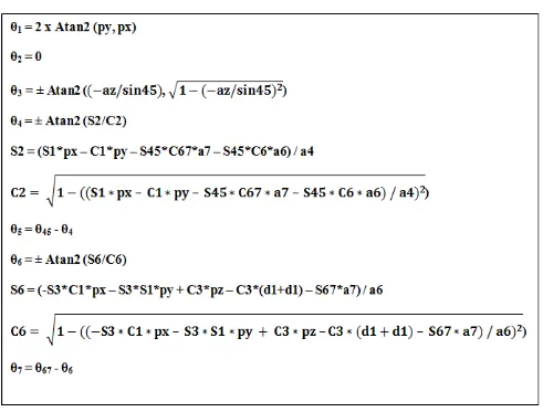
2) (13)Step 8: Similarly the other joint angles are found sequentially. The expressions for the joint angles are shown in Fig. 4.
Step 9: The known variables are substituted in the equations and the joint angles are found. The input variables are shown in Table 2.
Step 10: The Joint Angles are then tabulated as in Table 3.
[image:4.595.54.545.377.750.2]4.2
Sample calculation
[image:5.595.49.290.143.374.2]The robot parameters (link parameters) are constant. The required position and orientation of the end-effector of the robot is given as inputs.
Table 2. Inputs for Inverse Kinematics
αi
(degree) ai
(mm) di
(mm) nx ny nz
0 0 530 0.78 -0.06 0.62
90 0 220 ox oy oz
90 0 0 -0.63 -0.10 0.77
0 290 0 ax ay az
-90 0 0 0.02 -0.99 -0.12
0 180 0 px py pz
0 45 0 461.54 87.12 935.16
θ1 = 2 x Atan2 (py, px) (14)
As px is a positive integer then from the table 1 above the angle is calculated as,
θ1 = 2 x tan-1 (py / px) (15)
θ1 = 2 x tan-1 (87.09/ 461.57) = 21.37
θ2 = 0
Then θ3 = ± Atan2
(
(−az/sin45)
,1 − (−az/sin45)
2) (16)(- az / sin45) = (-(-0.12) / sin21.72) = 0.324
θ3 = + tan-1 (0.324 /
1 − (0.324)
2 = 18.906θ6 = ±Atan2((-S3*C1*px – S3*S1*py + C3*pz – C3*(d1+d1) –
S67*a7)/a6), 𝟏 − ((−𝐒𝟑 ∗ 𝐂𝟏 ∗ 𝐩𝐱 – 𝐒𝟑 ∗ 𝐒𝟏 ∗ 𝐩𝐲 + 𝐂𝟑 ∗ 𝐩𝐳 – 𝐂𝟑 ∗ (𝐝𝟏 + 𝐝𝟏) – 𝐒𝟔𝟕 ∗ 𝐚𝟕) / 𝐚𝟔)𝟐)
(17)
Since it is very complex, for the calculation purpose positive integers are only taken.
θ1 = 21.37, θ3 = 18.906 and θ67 = 23.22
((-S3*C1*px – S3*S1*py + C3*pz – C3*(d1+d1) – S67*a7) / a6) = 0.043
θ4 = ±Atan2((S1*px – C1*py – S45*C67*a7 – S45*C6*a6) /
a4), 1 − ((S1 ∗ px – C1 ∗ py – S45 ∗ C67 ∗ a7 – S45 ∗ C6 ∗ a6) / a4)2)
(18)
Since it has many terms consider only the positive of them for calculation
θ1 = 21.37, θ45 = 21.721, θ67 = 23.22, θ6 = 2.465
S1*px – C1*py – S45*C67*a7 – S45*C6*a6) / a4 = 0.018
θ4 = + tan-1 (0.018
/ 1 − (0.018)
2) = 1.048θ5 = θ45 - θ4 = 21.721 – 1.048 = 20.673
[image:5.595.319.534.303.493.2]Thus all the angles are successfully found.
Table 3. Final Angles Obtained From Manual Calculation
Angle Resultant value from manual calculation
θ1 21.37
θ2 0
θ3 18.906
θ4 1.048
θ5 20.673
θ6 2.465
θ7 20.755
5.
SOFTWARE DEVLOPMENT
Now-a-days software is available even to do the simple manipulation at a fast rate. The program codes are to be written in system language to develop the executable files. This software provides the platform for the understanding of the working of robot [6].
The software must be in the way to perform both forward as well as inverse kinematics. For forward kinematics, the height of lift and the angles of the corresponding joints are to be acquired as input parameters and the result is to produce the position of the end effector. For inverse kinematics, the desired position and orientation matrix of the end-effector are given as inputs and the joint variables are calculated.
The GUI is made in such a way that it describes the robot parameters in detail. It is made user friendly by the following aspects
3. The parameters involved in the robot are clearly defined and the final homogeneous matrix is provided on the separate screen.
4. The overall frame link assignment is also illustrated in the separate screen.
5. Separate windows are provided for forward and inverse kinematics.
6. The forward kinematics gives not only the final position of end-effector but the orientation matrix is also provided which is a input variable of inverse kinematics.
7. In inverse kinematics windows a sample calculation and the formula for calculation is depicted.
8. The final joint angles are provided in degrees rather than in radians.
The preceding features of the software make the robot user friendly. The windows are made multi-colored to differentiate the forward and inverse kinematics as shown in Fig. 7 and Fig. 8.
5.1
Algorithm
[image:6.595.322.538.72.320.2]The software is developed with proper algorithm as shown below. Fig. 5 depicts the algorithm which shows the choices provided to the user to control the software.
[image:6.595.101.498.413.717.2]
Fig 5: Algorithm development
Fig 7: Forward Kinematics Panel
Fig 8: Inverse Kinematics Panel
Table 4. Comparison of the software and Manual Results
Angle Result obtained from manual calculations
Result obtained from software
θ1 21.37 21.4
θ2 0 0
θ3 18.906 18.9
θ4 1.048 1.1
θ5 20.673 20.6
θ6 2.465 2.5
θ7 20.755 20.6
The technique of approximation is incorporated in the software which provides accurate results than the manual calculations.
6.
CONCLUSION
The inverse kinematics given away in this paper is found to be simple and easily understandable compared to many similar research works done in the past. The complete procedure of Inverse Kinematics is presented, which is also incorporated in Visual Basic language to develop the user friendly GUI. The unique feature of this newly developed software is conferred to show its significance and application. The comprehensive algorithm gives the complete knowledge of the software. The results obtained from the manual calculation and the software are compared and found close at hand. The manual results may be prone to fatal mistakes, but the feature of approximation has made the software to produce more accurate results consistently.
The future proposal is to perform the dynamic and workspace analysis. After authenticating the results to be safe the robot is fabricated and implemented in nuclear waste management to reduce the trepidation on nuclear industry. With these types of new inspection robot nuclear power production seems to be a safer means of power generation.
7.
ACKNOWLEDGMENTS
G.Shanmugasundar is very thankful to his research supervisor, Dr. R. Sivaramakrishnan, Associate Professor, Department of Production Technology, MIT, Chennai for his constant guidance and motivation throughout this research work. This work was supported by Dr. S. Venugopal, Head / Remote Handling, Irradiation Experiments and Robotics Division, Indira Gandhi Centre for Atomic Research, Government of India. The authors thank the anonymous reviewers for their helpful comments.
8.
REFERENCES
[1] Baki Koyuncu, and Mehmet Güzel, 2007 Software Development for the Kinematic Analysis of a Lynx 6 Robot Arm, World Academy of Science, Engineering and Technology 30
[2] Bruno Siciliano, Oussama Khatib, Springer Handbook of Robotics, (Springer-Verlag Berlin Heidelberg Springer ISBN: 978-3-540-23957-4 2008)
[3] De Xu, Carlos A. Acosta Calderon, John Q. Gan, Huosheng Hu, 2005 An Analysis of the Inverse Kinematics for a 5-DOF Manipulator, International Journal of Automation and Computing , 114-124
[4] J.Srinivas, R.V. Dukkipati, K.Ramji, 2009 Robotics Control and Programming, (New Delhi, Narosa Publishing House Pvt. Ltd, ISBN 978-81-7319-931-8).
[5] John J. Craig, Introduction to Robotics Mechanics and Control, PP 109-114, (Prentice Hall. 2005)
[6] Jorge Angeles, Fundamentals of Robotic Mechanical Systems: Theory, Methods, and Algorithms (Second Edition New York Springer, ISBN 0-387-95368-X)
[7] Li Han and Lee Rudolph, RSS 2006 Inverse Kinematics for a Serial Chain with Joints under Distance Constraints, Robotics: Science and Systems II pp. 177-184.
[8] Mohammed Reyad AbuQassem, 2010 Simulation and Interfacing of 5 DOF Educational Robot Arm, Master of Science dissertation submitted to Islamic University of Gaza Deanery of Graduate Studies Faculty of Engineering Electrical Engineering Department, June.
[9] R.K.Mittal, I.J.Nagrath, 2003 Robotics and Control, (New Delhi Tata McGraw-Hill Publishing Company Limited,.ISBN 0-07-048293-4).
[10]Rasit Koker, Cemil O z, Tarık Cakar, Huseyin Ekiz, 2004 A study of neural network based inverse kinematics solution for a three-joint robot, Robotics and Autonomous Systems 49 227–234
[11]S. Kumar, N. Sukavanam, And R. Balasubramanian, 2010 An Optimization Approach To Solve The Inverse Kinematics Of Redundant Manipulator, International Journal Of Information And Systems Sciences Volume 6, Number 4,. Pages 414–423
[12]Saeed B.Niku, Introduction to Robotics (New Jersey USA, Pearson Prentice Hall. 2001) ISBN-978-81-203-2379-7
[13]Sreenivas Tejomurtula, Subhash Kak, (1999) Inverse kinematics in robotics using neural networks, An International Journal of Information Sciences. Information Sciences 116 147-164
[14]Srinivas Neppalli, Matthew A. Csencsits, Bryan A. Jones, and Ian Walker,A, Geometrical Approach to Inverse Kinematics for Continuum Manipulators, International Conference on Intelligent Robots and Systems, Preprint submitted to 2008 IEEE/