N A N O E X P R E S S
Open Access
Conductivity of PEDOT:PSS on Spin-Coated
and Drop Cast Nanofibrillar Cellulose Thin Films
Dimitar Valtakari
1*, Jun Liu
2, Vinay Kumar
1, Chunlin Xu
2, Martti Toivakka
1and Jarkko J. Saarinen
1Abstract
Aqueous dispersion of conductive polymer poly(3,4-ethylenedioxythiophene)–poly(styrenesulfonate) (PEDOT:PSS) was deposited on spin-coated and drop cast nanofibrillar cellulose (NFC)–glycerol (G) matrix on a glass substrate. A thin glycerol film was utilized on plasma-treated glass substrate to provide adequate adhesion for the NFC-glycerol (NFC-G) film. The effects of annealing temperature, the coating method of NFC-G, and the coating time intervals on the electrical performance of the PEDOT:PSS were characterized. PEDOT:PSS on drop cast NFC-G resulted in 3 orders of magnitude increase in the electrical conductivity compared to reference PEDOT:PSS film on a reference glass substrate, whereas the optical transmission was only slightly decreased. The results point out the importance of the interaction between the PEDOT:PSS and the NFC-G for the electrical and barrier properties for thin film electronics applications.
Keywords:PEDOT:PSS; Nanofibrillar cellulose (NFC); Conductivity; Thin films
PACS:61.46.-w (structure of nanoscale materials); 68.37.-d (microscopy of surfaces, interfaces, and thin films); 81.05.Lg (polymers and plastics); 81.07.-b (nanoscale materials and structures: fabrication and characterization)
Background
Thin, lightweight, and flexible conductive films are use-ful for many applications from intelligent packaging, solar panels, radio frequency identification (RFID) tags to medical implants, wearable computers, and various sensors [1]. Traditionally, such films have been produced on plastics, glass, and other nonrenewable materials. However, the recent environmental concerns have re-sulted in the search for alternative and more sustainable materials. These must be cost-effective, widely available, and both ecologically and economically sustainable.
Cellulose is the most abundant biopolymer on the Earth and thus a suitable candidate for replacing fossil fuel-based solutions. Within the past decade, nanostruc-tured cellulose-based materials have raised large attention due to their unique properties. Nanofibrillar cellulose (NFC) has a high aspect ratio, large surface area, and high strength [2]. NFC can be utilized in various end-use prod-ucts ranging from thin films, coatings, and composites to aerogels and hydrogels. Recently, NFC-based conductive
films and composites for electronics applications have been studied; see, e.g., reviews [3, 4]. NFC films have good thermal [5–7] and chemical stability [8], tunable optical properties [5, 6, 9], high toughness [10], and low surface roughness [11]. Therefore, NFC films can be used as a substrate for flexible and transparent electronic de-vices for cost-effective manufacturing in a roll-to-roll process flow.
Various strategies have been employed to induce con-ductivity in NFC films. The NFC film can be coated [5, 8, 9, 12] or printed [9, 11, 13] with a conductive mater-ial. Alternatively, the conductive material can be inter-mixed with the NFC fibers that can be cast into a conductive composite film [6, 10, 14–17]. The conductive material can also be directly incorporated onto the NFC fibers using, for example, in situ chemical polymerization [18] or carbonization [19] that allows conductive films to be produced from such conductive fibers [20]. Different conductive materials such as silver nanowires [9, 12] or nanoparticles [11, 13], tin-doped indium oxide [9], carbon nanotubes (CNTs) [5, 8–10, 12, 14, 15, 17, 20, 21], graphene oxide [19], ZnSe quantum dots [6], polypyrrole [18], polyaniline doped with camphorsul-phonic acid [16], poly(p-phenylene ethynylene) [16]
* Correspondence:dimitar.valtakari@abo.fi
1Laboratory of Paper Coating and Converting, Center for Functional Materials (FunMat), Abo Akademi University, Porthansgatan 3, 20500 Åbo/Turku, Finland Full list of author information is available at the end of the article
and poly(3,4-ethylenedioxythiophene)– poly(styrenesul-fonate) (PEDOT:PSS) [5, 9, 20, 21] have been used in the literature. Nanostructured cellulose-based elec-tronics have been studied, e.g., in flexible supercapaci-tors [22], flexible nanopaper transissupercapaci-tors with high transmission and low surface roughness [23], photo-voltaic cells based on cellulose nanocrystal substrates [24], nonvolatile memory based on cellulose nanofiber paper [25], subcomponents made from nanofibrillar cellulose for “cut, stick and peel”-based flexible elec-tronics [26], and recently cellulose nanofibril paper-based high-performance flexible electronics [27].
PEDOT:PSS is a solution-processable conductive poly-mer that offers flexibility, high transparency, high ther-mal stability, low production cost, and compatibility with aqueous solution-based deposition techniques. PEDOT:PSS has a lower electrical conductivity than the other conductive polymers or metal oxides. However, the conductivity can be improved by addition of polyal-cohols such as glycerol [28], by adding polyelectrolytes [29], or by solvent [30] or an acid treatment [31, 32]. Highly conductive and transparent PEDOT:PSS films have been studied, e.g., for replacing indium tin oxide (ITO) in photovoltaics [33, 34] and touch screens [35]. Recently, a solar cell [9] and an OLED device [5] were demonstrated using a spin-coated conductive PED-OT:PSS on NFC substrate. Additionally, PEDPED-OT:PSS has been used with CNTs in the layer-by-layer coating of wood microfibers for paper-based batteries [20] and ca-pacitors [21].
In this work, we report a simple fabrication method of conductive PEDOT:PSS films on spin-coated or drop cast NFC-glycerol (NFC-G) layer on top of an oxygen plasma-activated glass substrate. We use glycerol as an anchor layer between the NFC-G layer and glass sub-strate since the NFC-G solution cannot be coated dir-ectly onto a pure plasma-activated glass substrate. A glycerol anchor layer provides good adhesion and repro-ducible results that allows a systematic study of the interaction between PEDOT:PSS and NFC-G coating. The electrical properties are studied as a function of the annealing temperature, the spin coating and drop casting of NFC, and the coating time intervals during film de-position. The effect of glycerol as a plasticizer on film formation and the resulting conductivity is discussed as well. PEDOT:PSS on NFC can be used to produce hu-midity or amine sensors, which can find applications in food packaging industry. These films can also be utilized in solar cell applications due to their tunable optical properties.
Methods
The NFC suspension was prepared from bleached birch Kraft pulp using 2,2,6,6-tetramethylpiperidine-1-oxyl
(TEMPO)-mediated oxidation followed by mechanical disintegration as reported by Liu et al.[36]. Ten grams of the pulp fibers were dispersed in 600 mL deionized (DI) water (Millipore 18.2 MΩ). The TEMPO (0.1 mmol/g fiber) and NaBr (1.0 mmol/g fiber) were dissolved in 300 mL DI water and then mixed with the pulp slurry. The concentration and the pH of the pulp were adjusted to 0.1 % and 10.0, respectively. The oxidation was started by adding the NaClO (10 mmol/g fiber) solution drop-wise. All NaClO solution was added for 8 h. During the reaction, the pH of the reaction mixture was kept at 10.5 by adding 0.5 M NaOH. After 24.0-h reaction, the mixture was precipitated in ethanol and purified by washing with DI water and centrifugation at 3500 rpm for 10 min for three times. The oxidized fibers were diluted to a concen-tration of 0.5 % and mechanically fibrillated with a domes-tic blender (OBH Nordica 6658, Denmark) for 5 min. The carboxylate content (1.79 ± 0.11 mmol/g) of the resulting NFC was determined by conductometric titration [36]. The chemicals were purchased from Sigma Aldrich and used without further purification.
The NFC and glycerol (≥99.0 %, Sigma-Aldrich, St. Louis, USA) solutions were prepared by weighing and diluting to given strengths using DI water and small 1.5 mL microcentrifuge tubes. All NFC-G coatings were well mixed and applied fresh on the surface immediately after the mixture preparation.
All samples were prepared on washed, cleaned, and dried clear microscope slide glasses cut into the size of 2.5 × 2.5 × 0.1 cm3. Furthermore, the glass slide surfaces were oxygen plasma treated in the etch mode in a high vacuum sample sputter coater (SCD 050, Bal-Tec AG, Balzers, Liechtenstein; now Leica Microsystems GmbH., Wetzlar, Germany) for 60 s at 20 mA and 0.05 mbar vacuum pressure for 3–15 min prior to spin coating. The plasma treatment lowered the water contact angle (KSV Cam 2000, Biolin Scientific Inc., Espoo, Finland) on the glass surface from 14° to 0°.
The spin-coated NFC-G layer serves two purposes as shown in Fig. 1: first, the PEDOT:PSS can be directly spin coated on top of it, and secondly, it serves as a rigid underlayer in which the drop cast NFC-G coating ad-heres preventing withdrawal from the edge during dry-ing. We wish to emphasize that NFC or NFC-G did neither adhere to the plain glass slide surface nor did it form a clean, uniform coating on the oxygen plasma-treated glass surface. However, addition of a 5.0 wt% gly-cerol coating as an anchor layer after the oxygen plasma surface treatment step resulted in good-quality spin-coated NFC-G films. The adhesion of the glycerol anchor layer was better on the oxygen plasma-coated surfaces than on an untreated plain glass. The glycerol coating has several advantages as it is colorless and semitransparent making it suitable for transmission measurements. It is also a plasticizer and a humectant for the NFC films to avoid brittleness and a well-known secondary dopant that can increase the overall electrical conductivity of the PEDOT:PSS by 2 to 3 orders of magnitude.
PEDOT:PSS samples were spin coated and annealed for 20 min at a given temperature range from 60 to 130 °C (Model 200, Memmert GmbH, Schwabach, Germany). Samples were kept aside prior to annealing for 20 to 30 min. Samples were stored overnight in dark and in humidity-controlled conditions at RH 50 % and measured for electrical conductivity on the following day. The sheet resistance was measured over two parallel hand-painted conductive silver paint (Electrolube) stripes
with inner borders 10 mm apart. A Keithley 2100 Digital Multimeter was used for sheet resistance measurements at 24 °C and RH 50 %. The scanning electron microscope (SEM, LEO 1530 VP Gemini, Carl Zeiss Microscopy Gmbh, Oberkochen, DE) was used to image the thickness and structure of the PEDOT:PSS-coated NFC-G samples on glass. These were either freeze-fractured after dipping in liquid N2 for a minimum of 5 s or alternatively frac-tured under ambient conditions. The sample light trans-mission was measured using a Perkin Elmer Lamba 900 spectrophotometer with an integrating sphere setup and the UV Winlab software.
Results and Discussion
The Effect of Annealing Temperature and NFC-G Mixture on the PEDOT:PSS Sheet Resistance
PEDOT:PSS aqueous dispersion coatings are typically annealed to increase their conductivity. Figure 2 shows the effect of annealing temperature on conductivity of the spin-coated PEDOT:PSS deposited on oxygen plasma-treated reference and glycerol-treated glass. The used annealing temperatures vary from 60 to 130 °C that are below the recommended drying temperature given by the polymer manufacturer of 130 °C. The PED-OT:PSS films become more stable above 80 °C, and the scatter in the measurement data decreases with the rais-ing annealrais-ing temperature. On a pure glass substrate, the PEDOT:PSS reaches a sheet resistance minimum at the 80 °C annealing temperature.
[image:3.595.57.540.88.321.2]The spin-coated PEDOT:PSS on glycerol anchor layer resulted in a significant drop in the sheet resistance values at lower annealing temperatures from 60 to 100 °C range. This is expected as glycerol is traditionally consid-ered as a secondary dopant for the PEDOT:PSS. It blends with the PEDOT:PSS and improves the conductivity by allowing the PEDOT and the PSS components to restruc-ture morphologically. The PEDOT:PSS conductivity can also be improved by blending, e.g., some polyols into the PEDOT:PSS that evaporate or pass through the PED-OT:PSS layer without a trace. On the glass substrates, the lowest sheet resistances are found in the middle and lower end of the used annealing temperature range.
The PEDOT:PSS coatings on drop cast NFC-G with a varying NFC concentration at 5.0 wt% glycerol in Fig. 3a show a significant decrease in the sheet resistance by 3 orders of magnitude compared to the reference PED-OT:PSS on glass without NFC. The drop cast NFC-G coatings were produced with three different NFC strengths, i.e., with three different viscosities while keep-ing the glycerol plasticizer level constant (5.0 wt%) in the NFC-G solution mixture. The 0.05 and 0.1 wt% NFC concentrations gave almost identical results. The sheet resistances dropped and leveled out with an increasing annealing temperature. The gel-like blend with the high-est viscosity of 0.2 wt% NFC had the highhigh-est sheet resist-ance. This can be caused by the reduced deformability of NFC due to the high viscosity, which can result in low-ered absorption and blending at the NFC/PEDOT:PSS interface. In the reference PEDOT:PSS, solvent evapor-ation takes place from a thin layer whereas NFC and gly-cerol absorb water from the aqueous PEDOT:PSS solution resulting in a different drying mechanism that
Fig. 2PEDOT:PSS sheet resistance on reference glass and glass with glycerol anchor layer
a
b
[image:4.595.57.541.89.301.2] [image:4.595.306.538.365.685.2]is susceptible for cracking. Therefore, on higher NFC concentrations, uneven shrinkage and mechanical stress during the annealing can result in cracking and reduced PEDOT:PSS film quality, and thus, a higher sheet ance as observed in Fig. 3a. However, the sheet resist-ance of PEDOT:PSS on drop cast NFC-G is significantly lower than the PEDOT:PSS reference.
Figure 3b shows the effect of glycerol concentration on the sheet resistance of PEDOT:PSS at a constant NFC con-centration of 0.1 wt%. The NFC itself is sufficient to re-duce the reference PEDOT:PSS sheet resistance levels by a factor of 30 from 550 kΩ/□down to <18 kΩ/□. This may be due to water still present in the NFC-G layer that can allow vapor transmission through and rearrangement of the PEDOT:PSS layer [37, 38]. The lowest sheet resistance is observed with the 5.0 wt% glycerol concentration, which is expected as glycerol is a secondary dopant for the PED-OT:PSS. However, a further increase of glycerol content to 10.0 wt% does not improve conductivity as the mechanical properties of the drop cast NFC-G layers start to fail and disintegrate during the spin coating. The overall PED-OT:PSS stability improves towards higher temperatures without the sheet resistance increase as observed in Fig. 2. We conclude that the pure drop cast NFC coating im-proves the PEDOT:PSS conductivity by an order of magni-tude. However, a much larger improvement is achieved through the combination of glycerol and water originating from the NFC-G mixture that allows vapor transmission and rearrangement of the PEDOT:PSS coating.
Sheet Resistance of PEDOT:PSS on Spin-Coated NFC-G
Drop casting is a slow process whereas spin coating pro-vides a fast track for prototyping. In our study, spin
coating of NFC-G films reduced the processing time from 24 h down to a few minutes. In addition, the sam-ple to samsam-ple variation was reduced with spin coating. This is especially important with multilayer structures as every additional sample preparation step with successive coating layers can be a source of error.
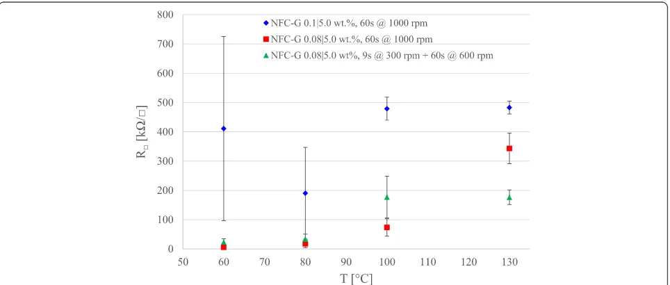
Figure 4 shows the PEDOT:PSS sheet resistances on a spin-coated NFC-G. We observe that PEDOT:PSS on 0.1/5.0 wt% NFC-G behaves similarly to the reference PEDOT:PSS spin-coated directly on a glass as shown in Fig. 2. The large standard deviations in the 60 and 80 °C points originate from the PEDOT:PSS instability that is absent in the 100 and 130 °C. Similar results indicate that the PEDOT:PSS and the NFC-G coatings act as sep-arate, isolate entities with no interaction between the two layers during the spin coating or annealing.
A reduction in NFC concentration from 0.1 wt% down to 0.08 wt% produces an NFC-G mixture with a lower viscosity. Thus, at a constant spinning rate (1000 rpm), a thinner film will be produced. The sheet resistance of the PEDOT:PSS is reduced due to the PEDOT:PSS inter-action with the glycerol at 60 and 80 °C. Furthermore, a slow initialization rate at 300 rpm will retain more liquid on the substrate that results in a thicker film. At lower temperatures, the sheet resistances remain at the previ-ous levels whereas at 100 and 130 °C, the performance is stabilized approximately to 200 kΩ/□ that is significantly lower compared to the PEDOT:PSS reference (550 kΩ/□).
We can conclude that the higher NFC concentration of 0.1 wt% forms a tight and dense layer with sufficient barrier properties to prevent the glycerol interaction with the PEDOT:PSS. On the other hand, at a lower NFC concentration of 0.08 wt%, the NFC-G layer is less
[image:5.595.58.540.499.704.2]dense allowing the glycerol to migrate into the PED-OT:PSS layer during the spin coating and annealing. The 100 °C point suggests that the NFC component dries quicker and becomes restrictive, blocking the glycerol and water from the PEDOT:PSS. Hence, the spin-coated NFC-G films can be customized to act as either a barrier (0.1 wt% NFC) or as a regulator (0.08 wt% NFC) that controls the release of glycerol and water into the PED-OT:PSS layer.
Finally, the time dependence of the start of the anneal-ing from the PEDOT:PSS coatanneal-ing is shown in Fig. 5. It is clearly seen that starting the annealing instantly 1 min after the coating results in lower sheet resistance with lower annealing temperatures than the 3-min interval. The 1-min samples have higher moisture content, and the samples annealed at higher temperatures may drive the water and perhaps some glycerol rapidly out from the PEDOT:PSS/NFC-G interface region, disallowing PEDOT and PSS to rearrange. The sheet resistance levels in Fig. 5 at 80 °C are approximately twice as high to those in Fig. 4. A closer look reveals that the 3-min sam-ples have a similar instability issue at 60 °C as with the PEDOT:PSS reference response shown in Fig. 2. The overall performance improves and becomes more stable converging to 300–400 kΩ/□ sheet resistance level be-tween annealing temperatures of 80 and 130 °C.
Coating Thickness, Wetting Characteristics, and Optical Transmission
An objective with our NFC-G model system on glass substrate was to retain the same semitransparent charac-ter provided by unsupported, standalone NFC films. The benefit of our model system is that the flat NFC-G films supported on the glass are suitable for the PEDOT:PSS
spin coating. Our conductivity results in Figs. 2, 3, 4, and 5 show that these samples are reproducible and thus suitable both for electrical and optical characterization.
The sample thicknesses of the PEDOT:PSS-coated NFC-G layers were determined using SEM. The samples were either annealed at 130 °C or left as such with no annealing. The annealing step is essential for the con-ductivity, electrical stability, and smoothness of the PED-OT:PSS layer. Annealing causes shrinkage of the PEDOT:PSS liquid dispersion particle, vertical segrega-tion into a mainly PEDOT phase at the bottom, and a PSS phase on top as well as degradation over a pro-longed exposure to heat [39].
Figure 6 shows cross sections of the PEDOT:PSS samples with and without annealing together with the spin-coated reference PEDOT:PSS on the oxygen plasma-activated glass on top (a). The annealed samples are shown to the left in Fig. 6 with spin coating (b1) and drop casting (c1) and the corresponding samples without an-nealing to the right, spin coated (b2), and drop cast (c2). The spin coating causes film shrinkage due to compres-sion and fast evaporation of water from the thin films. Furthermore, annealing causes shrinkage due to drying. The cross section samples for the SEM imaging are com-monly freeze fractured in liquid nitrogen. Unfortunately, moisture absorbed from the surrounding air can cause sample swelling with hygroscopic materials. In Fig. 6, on the left (a1, b1, c1), all drying steps are present, whereas on the right (b2, c2), the drying steps were reduced to a minimum. Finally, the cross section samples to the right were fractured at room temperature without freezing.
The spin-coated PEDOT:PSS sample without annealing (b2) has a thickness of 127 nm. This is slightly less com-pared to the 138–145 nm of the annealed and
[image:6.595.57.538.503.716.2]fractured counterpart (b1). This suggests that the spin-coated NFC-G has a dense texture being fairly resistant to the moisture. This is also supported by the water contact angle results. The spherical PEDOT:PSS water dispersion particles can be distinguished on the surface in the sample (b2). This suggests that the spin-coated NFC-G layer ac-counts for approximately 80 nm and the PEDOT:PSS rest-ing on top the remainrest-ing 47 nm from the total thickness of 127 nm.
The drop cast PEDOT:PSS samples have a significantly thicker NFC-G layer than the spin-coated counterparts as drop-casting produces a less dense texture with high water release and uptake ability. The drop cast PED-OT:PSS-coated sample shrank during annealing. How-ever, the sample swells after the freeze fracturing to 438–485 nm as seen in the sample (c1). Of the total thickness of 274 nm in the sample (c2) without anneal-ing, approximately 230 nm belongs to the NFC compo-nent. The water contact angle results show that the
PEDOT:PSS coating on top provides a barrier to mois-ture. Therefore, it is reasonable to assume that the swell-ing is mainly caused by moisture enterswell-ing from the open face of the fractured side, not from the top.
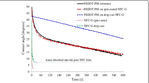
Water contact angle measurements are shown in Fig. 7. The PEDOT:PSS-coated samples were annealed at 130 °C, and all the samples were stored at RH 50 % and measured 24 h after sample preparation was completed. The spin-coated and drop cast pure NFC samples are highly hydro-philic with the latter showing very strong absorption of water between the 15 and 40-s time interval causing swell-ing and deformation of the NFC layer. Some marks from the drying water droplets were observed on the surface of the spin-coated NFC after completed drying. This indi-cates a limited water absorption into the NFC layer. We also tested the water contact angles on glycerol film, and the results were visually identical to the spin-coated NFC except the strong uneven and noncircular wetting pattern outwards from the wetting center.
a)
b1)
c1)
b2)
c2)
[image:7.595.56.542.89.456.2]The PEDOT:PSS films were less hydrophilic in com-parison to the uncoated NFC-G layers. The spin-coated PEDOT:PSS on NFC-G behaved identically to the PED-OT:PSS reference on glass. This indicates that the sessile drop method is insensitive to the morphological changes that can take place in the spin-coated PEDOT:PSS on NFC-G resulting in a better conductivity. The PED-OT:PSS on drop cast NFC-G shows approximately 15° higher water contact angles than the reference PED-OT:PSS. In general, the annealing step has a smoothen-ing effect on the PEDOT:PSS films. However, this may be compromised by the pores and pinholes in the NFC-G layer caused by water and glycerol evaporation through the PEDOT:PSS film. Nevertheless, the barrier properties of the PEDOT:PSS coating are quite remark-able as the water contact angle drops monotonously, at the same rate as the reference, suggesting only a limited water absorption. Visual inspection of the samples re-vealed only light marks on the surface from the drying water droplet.
The optical transmission results are in Fig. 8 for the coated PEDOT:PSS on reference glass and on spin-coated and drop cast NFC-G. The spin-spin-coated sample data overlaps with that of the reference with transmis-sion varying from approximately 94 to 84 % for the wavelength range 350–850 nm. Both maintain the same light blue color shade, and the components in the NFC-G layer seem not to affect the transmission. This is in accordance by the dense texture and strong barrier
properties of the NFC-G layer observed in the SEM and the contact angle measurements. On the other hand, the PEDOT:PSS on drop cast NFC-G has 1 to 8 points lower transmission across the measured spectral range of 350– 850 nm. The transmission loss is a fairly small sacrifice in comparison to the enhanced conductivity increase of three orders of magnitude. The transmission loss is caused by a small color shift towards deeper blue as a result of the PEDOT:PSS absorption into the NFC-G layer. The PEDOT:PSS liquid dispersion consists of more than 95 % water that is easily absorbed by the drop cast NFC-G layer as seen in the contact angle measurement results in Fig. 7. The same applies to the PEDOT:PSS li-quid dispersion. The submicron thickness of the color-less and semitransparent NFC-G film has a minor impact on the transmission drop. Transmission results for samples annealed at temperatures from 60 to 130 °C were rather similar, and the results stayed within one percentage point for all spin-coated samples and within 3 percentage points for all drop cast samples.
Conclusions
The conductive polymer PEDOT:PSS is typically applied on transparent surfaces such as glass or plastic film. Our work is focused on PEDOT:PSS on NFC-G, which can produce stand-alone, semi-transparent films. NFC can provide sustainable, recyclable, and biodegradable alter-natives to glass and plastic substrates.
0 5 10 15 20 25 30 35 40 45 50
0 60 120 180 240 300 360 420 480 540 600
Contact angle [degrees]
Time [s]
PEDOT:PSS reference
PEDOT:PSS on spin coated NFC-G
PEDOT:PSS on drop cast NFC-G
NFC-G spin coated
NFC-G drop cast
water absorbed into the pure NFC film
[image:8.595.59.540.89.357.2]Pure NFC films are very brittle but can be converted to flexible ones by blending with a suitable plasticizer. Here, we use glycerol as a plasticizer due to its additional multifunctional characteristics: it is colorless, semitrans-parent, adhesive, water-soluble, and a well-known second-ary dopant for the PEDOT:PSS. The semi-transparent NFC film, unlike glass and plastic, can have added func-tionality and be an active substrate with tailored properties that will interact and enhance the conductivity of the coated PEDOT:PSS on top of the NFC-G.
NFC films are most commonly produced through drop casting that is a time-consuming process. The dry film does not adhere to glass or plastic substrate. Gluing the NFC film onto a solid substrate may alter the optical and structural film characteristics. Therefore, an optic-ally semi-transparent model system was developed to study the PEDOT:PSS interaction on an NFC-G layer immobilized on glass either through drop casting or spin coating. These techniques enable spin coating of PED-OT:PSS on top of the NFC-G sample combining fast prototyping with good reproducibility. The electrical conductivity of PEDOT:PSS improved 3 orders of mag-nitude on the drop cast NFC-G samples. The high con-ductivity is a combined result from the water content and the glycerol in the NFC-G film allowing annealing of the samples across a broader temperature range.
The spin-coated PEDOT:PSS on NFC-G samples pro-vided a sensitive study platform. The conductivity levels were much lower than with drop cast NFC-G, but the changes in conductivity levels allowed a better under-standing about the interaction between the PEDOT:PSS and the NFC-G. Clearly, the water content has a
significant impact on the PEDOT:PSS. More import-antly, the moisture level in the NFC-G film has a de-cisive impact on the PEDOT:PSS conductivity level when the samples are annealed. Environmental stability of the transparent, conductive PEDOT:PSS films on NFC-G substrate is a key property for practical applica-tions that can either degrade the electrical functionality or be utilized, for example, in gas or humidity sensing of the environment. This work was carried out in well-controlled conditions to study fundamental interactions between PEDOT:PSS and NFC-G with minimized envir-onmental variables. We plan to return on this issue in a future communication.
We believe that conductive PEDOT:PSS films on NFC-G have potential for many applications in flexible electronics and sensors in the future.
Competing interests
The authors declare that they have no competing interests.
Authors’contributions
DV, VK, MT, and JJS designed and planned the experiments. JL and CX fabricated the nanofibrillar cellulose (NFC). DV conducted all the experiments and performed the data analysis. DV wrote the manuscript. All authors read and approved the final manuscript.
Acknowledgements
This work has been funded by the Academy of Finland (grants no. 250 122, 256 263 and 283 054). The Physics Laboratory staff at Abo Akademi University are greatly acknowledged for all the help, equipment, and facilities employed in this work. MSc Björn Törngren is acknowledged for performing the optical transmission measurements at the Laboratory of Physical Chemistry at Abo Akademi University. SEM samples were measured by M.Sc. Linus Silvander at the Laboratory of Inorganic Chemistry at the Abo Akademi University, Finland.
76 78 80 82 84 86 88 90 92 94 96
850 800 750 700 650 600 550 500 450 400 350
Transmission [%]
Wavelength [nm]
PEDOT:PSS reference
PEDOT:PSS on spin coated NFC-G PEDOT:PSS on drop cast NFC-G
[image:9.595.61.538.89.315.2]Author details
1
Laboratory of Paper Coating and Converting, Center for Functional Materials (FunMat), Abo Akademi University, Porthansgatan 3, 20500 Åbo/Turku, Finland. 2
Laboratory of Wood and Paper Chemistry, Abo Akademi University, Porthansgatan 3, 20500 Åbo/Turku, Finland.
Received: 12 August 2015 Accepted: 27 September 2015
References
1. Irimia-Vladu M, Głowacki ED, Voss G, Bauer S, Sariciftci NS (2012) Green and biodegradable electronics. Mater Today 15:340–346
2. Kumar V, Bollström R, Yang A, Chen Q, Chen G, Salminen P, Bousfield D, Toivakka M (2014) Comparison of nano- and microfibrillated cellulose films. Cellulose 21:3443–3456
3. Salas C, Nypelö T, Rodriguez-Abreu C, Carrillo C, Rojas OJ (2014) Nanocellulose properties and applications in colloids and interfaces. Curr Opin Colloid Interface Sci 19:383–396
4. Shi Z, Phillips GO, Yang G (2013) Nanocellulose electroconductive composites. Nanoscale 5:3194–3201
5. Zhu H, Xiao Z, Liu D, Li Y, Wadock NJ, Fang Z, Huang J, Ku L (2013) Biodegradable transparent substrates for flexible organic-light-emitting diodes. Energy Environ Sci 6:2105–2111
6. Xue J, Song F, Yin X, Wang X, Wang Y (2015) Let it shine: a transparent and photoluminescent foldable nanocellulose/quantum dot paper. ACS Appl Mater Interfaces 7:10076–10079
7. Fukuzumi H, Saito T, Iwata T, Kumamoto Y, Isogai A (2009) Transparent and high gas barrier films of cellulose nanofibers prepared by TEMPO-mediated oxidation. Biomacromolecules 10:162–165
8. Zheng G, Cui Y, Karabulut E, Wågberg L, Zhu H, Hu L (2013) Nanostructured paper for flexible energy and electronic devices. MRS Bull 38:320–325 9. Hu L, Zheng G, Yao J, Liu N, Weil B, Eskilsson M, Karabulut E, Ruan Z, Fan S,
Bloking JT, McGehee MD, Wågberg L, Cui Y (2013) Transparent and conductive paper from nanocellulose fibers. Energy Environ Sci 6:513–518 10. Salajkova M, Valentini L, Zhou Q, Berglung LA (2013) Tough and conductive
nanopaper structures based on cellulose nanofibrils and carbon nanotubes. Compos Sci Technol 87:103–110
11. Torvinen K, Sievänen J, Hjelt T, Hellén E (2012) Smooth and flexible filler-nanocellulose composite structure for printed electronics applications. Cellulose 19:821–829
12. Hu L, Choi JW, Yang Y, Jeong S, La Mantia F, Cui L, Cui Y (2009) Highly conductive paper for energy-storage devices. Proc Natl Acad Sci U S A 106:21490–21494
13. Penttilä A, Sievänen J, Torvinen K, Ojanperä K, Ketoja JA (2013) Filler-nanocellulose substrate for printed electronics: experiments and model approach to structure and conductivity. Cellulose 20:1413–1424
14. Koga H, Saito T, Kitaoka T, Nogi M, Suganuma K, Isogai A (2013) Transparent, conductive, and printable composites consisting of TEMPO-oxidized nanocellulose and carbon nanotube. Biomacromolecules 14:1160–1165 15. Yoon SH, Jin H, Kook M, Pyun YR (2006) Electrically conductive bacterial cellulose by incorporation of carbon nanotubes. Biomacromolecules 7:1280–1284
16. van den Berg O, Schroeter M, Capadona JR, Weder C (2007) Nanocomposites based on cellulose whiskers and (semi)conducting conjugated polymers. J Mater Chem 17:2746–2753
17. Hamedi MM, Hajian A, Fall AB, Håkansson K, Salajkova M, Lundell F, Wågberg L, Berglund A (2014) Highly conducting, strong nanocomposites based on nanocellulose-assisted aqueous dispersions of single-wall carbon nanotubes. ACS Nano 8:2467–2476
18. Nyström G, Mihranyan A, Razaq A, Lindström T, Nyholm L, Strømme M (2010) A nanocellulose polypyrrole composite based on microfibrillated cellulose from wood. J Phys Chem B 114:4178–4182
19. Li Y, Zhu H, Shen F, Wan J, Han X, Dai J, Dai H, Hu L (2014) Highly conductive microfiber of graphene oxide templated carbonization of nanofibrillated cellulose. Adv Funct Mater 24:7366–7372
20. Aliahmad N, Agarwal M, Shrestha S, Varahramyan K (2013) Paper-based lithium-ion batteries using carbon nanotube-coated wood microfibers. IEEE Trans Nanotechnol 12:408–412
21. Agarwal M, Xing Q, Shim BS, Kotov N, Varahramyan K, Lvov Y (2009) Conductive paper from lignocellulose wood microfibers coated with a
nanocomposite of carbon nanotubes and conductive polymers. Nanotechnology. doi:10.1088/0957-4484/20/21/215602
22. Gao K, Shao Z, Li J, Wang X, Peng X, Wang W, Wang F (2013) Cellulose nanofiber-graphene all solid-state flexible supercapacitors. J Mater Chem A 1:63–67
23. Huang J, Zhu H, Chen Y, Preston C, Rohrbach K, Cumings J, Hu L (2013) Highly transparent and flexible nanopaper transistors. ACS Nano 7:2106–2113 24. Zhou Y, Fuentes-Hernandez C, Khan TM, Liu J, Hsu J, Shim JW, Dindar A,
Youngblood JP, Moon RJ, Kippelen B (2014) Efficient recyclable organic solar cells on cellulose nanocrystal substrates with a conducting polymer top electrode deposited by film-transfer lamination. Org Electron 15:661–666 25. Nagashima K, Koga H, Celano U, Zhuge F, Kanai M, Rahong S, Meng G, He Y, De Boeck J, Jurczak M, Kitaoka T, Nogi M, Yonagida T (2014) Cellulose nanofiber paper as an ultra flexible nonvolatile memory. Sci Rep. doi:10.1038/srep05532
26. Kuwahara J, Ersman PA, Wang X, Gustafsson G, Granberg H, Berggren M (2013) Reconfigurable sticker label electronics manufactured from nanofibrillated cellulose-based self-adhesive organic electronic materials. Org Electron 14:3061–3069
27. Jung YH, Chang T, Zhang H, Yao C, Zheng Q, Yang VW, Mi H, Kim M, Cho SJ, Park D, Jiang H, Lee J, Qiu Y, Zhou W, Cai Z, Gong S, Ma Z (2015) High-performance green flexible electronics based on biodegradable cellulose nanofibril paper. Nature Commun 6:7170
28. Ouyang J, Chu C, Chen F, Xu Q, Yang Y (2005) High-conductivity poly(3,4-ethylenedioxythiophene): poly(styrenesulfonate) film and its application in polymer optoelectronic devices. Adv Funct Mater 15:203–208
29. Valtakari D, Bollström R, Toivakka M, Saarinen JJ (2015) Influence of anionic and cationic polyelectrolytes on the conductivity and morphology of poly(3,4-ethylenedioxythiophene):poly(styrenesulfonate) films. Thin Solid Films 590:170–176
30. Yan H, Jo T, Okuzaki H (2009) Highly conductive and transparent PEDOT/ PSS thin films. Polym J 41:1028–1029
31. Howden RM, McVaya ED, Gleason KK (2013) oCVD
poly(3,4-ethylenedioxythiophene) conductivity and lifetime enhancement via acid rinse dopant exchange. J Mater Chem A 1:1334–1340
32. McCarthy JE, Hanley CA, Brennan LJ, Lambertini VG, Gun’ko YK (2014) Fabrication of highly transparent and conducting PEDOT:PSS films using a formic acid treatment. J Mater Chem C 2:764–770
33. Vosgueritchian M, Lipomi DJ, Bao Z (2012) Highly conductive and transparent PEDOT:PSS films with a fluorosurfactant for stretchable and flexible transparent electrodes. Adv Funct Mater 22:421–428 34. Kim YH, Sachse C, Machala ML, May C, Müller-Meskamp L, Leo K (2011)
Highly conductive PEDOT:PSS electrode with optimized solvent and thermal post-treatment for ITO-free organic solar cells. Adv Funct Mater 21:1076–1081 35. Yan H, Jo T, Okuzaki H (2011) Potential application of highly conductive and
transparent poly(3,4-ethylenedioxythiophene)/poly(4-styrenesulfonate) thin films to touch screen as a replacement for indium tin oxide electrodes. Polym J 43:662–665
36. Liu J, Korpinen R, Mikkonen KS, Willför S, Xu C (2014) Nanofibrillated cellulose originated from birch sawdust after sequential extractions: a promising polymeric material from waste to films. Cellulose 21:2587–2598 37. Friedel B, Keivanidis PE, Brenner TJ, Abrusci A, McNeill CR, Friend RH,
Greenham NC (2009) Effects of layer thickness and annealing of PEDOT:PSS layers in organic photodetectors. Macromolecules 42:6731–6747
38. Friedel B, Brenner TJK, McNeill CR, Steiner U, Greenham NC (2011) Influence of solution heating on the properties of PEDOT:PSS colloidal solutions and impact on the device performance of polymer solar cells. Org Electron 12:1736–1745