N A N O E X P R E S S
Open Access
Effect of triplet multiple quantum well structures
on the performance of blue phosphorescent
organic light-emitting diodes
Seokjae Lee
1†, Jaryong Koo
1†, Gunwoo Hyung
1†, Donghwan Lim
1, Donghyung Lee
1, Kumhee Lee
2†,
Seungsoo Yoon
2*, Wooyoung Kim
3and Youngkwan Kim
1*Abstract
We investigate multiple quantum well [MQW] structures with charge control layers [CCLs] to produce highly efficient blue phosphorescent organic light-emitting diodes [PHOLEDs]. Four types of devices from one to four quantum wells are fabricated following the number of CCLs which are mixed p- and n-type materials, maintaining the thickness of the emitting layer [EML]. Remarkably, such PHOLED with an optimized triplet MQW structure achieves maximum luminous and external quantum efficiency values of 19.95 cd/A and 10.05%, respectively. We attribute this improvement to the efficient triplet exciton confinement effect and the suppression of triplet-triplet annihilation which occurs within each EML. It also shows a reduction in the turn-on voltage from 3.5 V (reference device) to 2.5 V by the bipolar property of the CCLs.
Background
Due to their high efficiency, phosphorescent organic emitting diodes [PHOLEDs] are promising light-emitting materials in organic light-light-emitting diodes [OLEDs]. An internal quantum efficiency of 100% could be realized in red and green PHOLEDs [1,2]. However, the performance of blue PHOLEDs still needs to be improved for lighting applications. Light emission in PHOLEDs depends on the properties of the organic material in the devices [3,4]. In particular, the energy level of the charge transport, host, and emitter materials influences the light-emitting efficiency. Besides, many different device architectures have attempted to improve the light-emitting efficiency of PHOLEDs. Hole and electron blocking layers or triplet exciton blocking layers [TEBLs] in PHOLEDs were introduced to confine both carriers and excitons within emitting layers [EMLs] [5]. A double emitting layer structure was also employed in OLEDs by utilizing phosphorescent materials doped in
two different hosts. As a result, these ways were effective in providing higher efficiency in PHOLEDs [6].
Another way to achieve high efficiency in OLEDs is to confine excitons inside the EML using the multiple quantum well [MQW] structure [7]. Only a few reports concerning the MQW structure with good carrier and exciton confinement ability have been presented on OLEDs until quite recently. For example, Qiu et al. [7] improved the charge balance by utilizing an organic MQW structure to decelerate hole transportation. Huang et al. [8] used MQW structures to increase the carrier recombination efficiency, where both charges and excitons were confined to the EMLs. Park et al. [9] and Kim et al. [10] also reported similar triplet MQW structures. Recently, Liu et al. [11] proposed a non-dop-ing EML method, instead of a host-emitter dopnon-dop-ing method, to improve the efficient triplet exciton confine-ment effect and the suppression of triplet-triplet annihi-lation that occurs via a single-step long range (Forster-type) energy transfer between excited molecules.
In this paper, we demonstrate efficient blue PHOLEDs by using iridium(III) bis[(4, 6-di-fluorophenyl)-pyridi-nato-N,C2’
]picolinate [FIrpic] doped inN,N’ -dicarbazo-lyl-3, 5-benzene [mCP] with charge control layers [CCLs] as an MQW structure. The device architecture
* Correspondence: [email protected]; [email protected] †Contributed equally
1
Department of Information Display, Hongik University, Seoul, 121-791, South Korea
2
Department of Chemistry, Sungkyunkwan University, Suwon, 440-746, South Korea
Full list of author information is available at the end of the article
was developed to confine excitons inside each EML and to manage triplet excitons by controlling the charge injection. A stacked recombination zone structure, which can prevent triplet quenching processes and tri-plet exciton confinement within recombination region, was designed, and its performance was compared with that of blue devices. In addition, a mixed CCL, which has a p-type mCP and an n-type 2, 2’,2"-(1, 3, 5-benze-netryl)tris(1-phenyl)-1H-benzimidazol [TPBi], reduced the turn-on voltage and enhanced efficiencies by prohi-biting triplet exciton diffusion out of each EML.
Methods
A glass substrate coated with a 180-nm-thick indium tin oxide [ITO] layer has a sheet resistance of 12Ω/sq. The ITO was cleaned with acetone, methanol, distilled water, and isopropyl alcohol in an ultrasonic bath. The pre-cleaned ITO was then treated with O2 plasma with the
conditions of 2 × 10⁻² Torr, 125 W, and 2 min. All
organic layers were sequentially deposited onto the sub-strate without breaking the vacuum at a pressure of 5 × 10⁻⁷Torr, using thermal evaporation equipment. The deposition rates were 1.0 to 1.1 Å/s for organic materi-als and 0.1 Å/s for lithium quinolate [Liq]. Finally, the aluminum cathode was deposited at a rate of 10 Å/s. The deposition rates were controlled with a quartz crys-tal monitor, and the doping concentrations of the emit-ters were optimized. After the organic and metal depositions, the devices were encapsulated in a glove box with O2 and H2O at concentrations below 1 ppm. A desiccant material consisting of barium oxide powder was used to absorb the residue moisture and oxygen in the encapsulated device. The devices had emission areas of 3 × 3 mm. The voltage, luminance, luminous effi-ciency, external quantum effieffi-ciency, power effieffi-ciency, and current density characteristics were measured and immediately recorded with a Chroma meter CS-1000A (Konica Minolta Holdings, Inc., Chiyoda, Tokyo, Japan). The current and voltage were controlled with a mea-surement unit (model 236, Keithely Instruments Inc., Cleveland, OH, USA).
Results and discussion
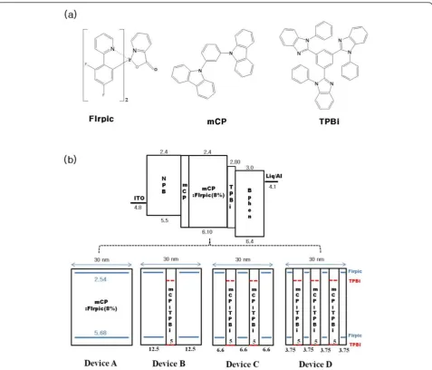
Figure 1a shows the chemical structures of FIrpic, mCP, and TPBi materials of blue PHOLEDs. FIrpic is the most well-known phosphorescent blue emitter, and mCP, as a carbazole-based material, is known to be a potential host material for blue electrophosphorescence because of its wide bandgap energy, high triplet energy, and good hole-transporting ability [12-14]. In addition, the high electron mobility of TPBi that provides good transport characteristics and barrier height of exciton diffusion out of EMLs do not exist due to the high
triplet energy level of TPBi [15]. Figure 1b shows the structures and energy level diagrams of blue PHOLEDs (devices A, B, C, and D). A series of phosphorescent blue devices were prepared with the structure of ITO as an anode; N,N’-bis-(1-naphyl)-N,N’-diphenyl-1, 1’ -biphenyl-4, 4’-diamine (NPB, 50 nm) as a hole trans-porting layer; mCP (5 nm) as a TEBL; single EML (device A) or MQW structure EMLs (devices B, C, and D); TPBi (10 nm) as a TEBL and electron transporting layer [ETL]; 4, 7-diphenyl-1, 10-phenanthroline (BPhen, 30 nm) as an ETL; Liq (2 nm) as an electron injection layer; and aluminum (Al, 100 nm) as a cath-ode. As shown in Figure 1b, devices A, B, C, and D have the following EML structure: device A, FIrpic doped in mCP (30 nm) as a reference device; device B, nconsists of [FIrpic doped in mCP (12.5 nm)]n = 2and [CCL (mCP/TPBi = 1:1, 5 nm)]n = 1; device C, n con-sists of [FIrpic doped in mCP (6.6 nm)]n= 3 and [CCL (mCP/TPBi = 1:1, 5 nm)]n = 2; device D, n consists of
[FIrpic doped in mCP (3.75 nm)]n = 4 and [CCL
(mCP/TPBi = 1:1, 5 nm)]n = 3 as an MQW structure
device, where the doping concentrations of FIrpic were optimized at 8 wt.%, respectively. MQW structure devices with CCLs, which were a mixed mCP of hole transport type and TPBi of electron transport type, can control the carrier movement with ease.
Figure 2 shows the lowest triplet states [T1] of materi-als, such as TEBL, EML, and CCL, and the triplet exci-ton transfer mechanism in [EML]n= 2and [CCL]n= 1of the triplet MQW structure. Both triplet exciton transfer and energy transition are shown in dotted arrows, while phosphorescence from the T1 state to the ground state is shown in solid arrows. The T1of mCP and TPBi were 2.90 eV and 2.73 eV, respectively, compared to 2.65 eV for FIrpic [16,17]. From their triplet state alignments, it can be speculated that there should be an efficient exothermic energy transfer from the host material triplet states to the FIrpic triplet state as well as an excellent triplet energy confinement on the FIrpic molecules within each EML. It is important to suppress any back energy transfer from the emitter triplet states to the others and enable consumption of all the electrically generated triplet excitons contributing to the emission.
n-type TPBi, for controlling the carrier movement. The CCLs, including the TPBi of good electron-transporting ability, enhanced the movement of electrons within the
EML and helped the holes’movement slow down
com-pared with conventional single EML without any CCLs. In this result, the turn-on voltage of devices B, C, and D are lower than that of device A. This also indicates that devices B, C, and D are better than device A for charge balance within EMLs.
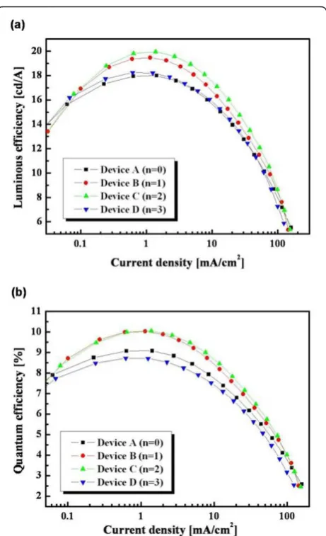
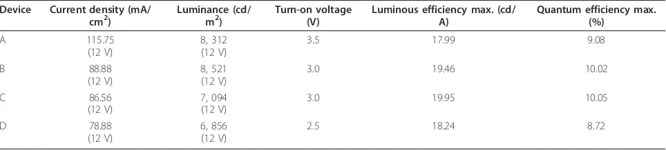
The current density, luminous efficiency, and quantum efficiency of devices A, B, C, and D were compared, as shown in Figure 4a, b. The maximum luminous efficien-cies of devices A, B, C, and D were 17.99, 19.46, 19.95, and 18.24 cd/A, and the maximum quantum efficiencies of devices A, B, C, and D were 9.08%, 10.02%, 10.05%, and 8.72%, respectively. As with device C with a triplet
MQW structure, n consists of [FIrpic doped in mCP
[image:3.595.60.538.87.495.2]recombination zones, the triplet exciton diffusions are prohibited inside each EML by CCLs with a high triplet state (T1). It effectively reduces exciton quenching pro-cesses, such as triplet annihilation and triplet-polaron annihilation [18,19]. In the case of device D
with a triplet MQW structure, n consists of [FIrpic
doped in mCP (3.75 nm)]n= 4; [CCL (mCP/TPBi = 1:1, 5 nm)]n = 3 shows lower efficiencies than the other devices due to a relatively narrow emissive region.
Conclusions
In conclusion, the present study reports on the high effi-ciency blue PHOLEDs based on a carrier and triplet
[image:4.595.307.538.85.464.2]exciton confinement inside recombination zones by using a triplet multiple quantum structure. The triplet energies of mCP and TPBi are higher than those of FIr-pic. Therefore, triplet multiple quantum structures with CCLs exhibited efficient carrier and triplet exciton con-finement within each EML. Moreover, CCLs can play a role in carrier movement with ease and triplet exciton blocking as expected from high triplet energy levels. In the electrical characteristic results of blue devices, the properties of device C with three recombination zones were found to be superior to the properties of devices A, B, and D. We attribute such high efficiencies and reduced turn-on voltage to the following two advantages caused by the triplet MQW structure: (1) efficient charge and exciton confinement effect by CCLs and TEBLs with high triplet energy level and (2) charge transportation balance in each EML by CCLs with Figure 3 Electrical characteristics of blue PHOLEDs. The
[image:4.595.58.291.89.235.2]luminance versus voltage characteristics (inset: current density versus voltage characteristics) of devices A, B, C, and D. The dotted circle on the graph shows reduction in the turn-on voltage from 3.5 V of the reference device (device A) to 2.5 V of the MQW structure device (device D).
Figure 2Schematic drawing of triplet energy levels. The lowest triplet states (T1) of materials, such as TEBL, EML, and CCL, and the triplet exciton transfer mechanism in [EML]n= 2and [CCL]n= 1of the triplet MQW structure. Both triplet exciton transfer and energy transition are shown in dotted arrows, while phosphorescence from theT1state to the ground state is shown in solid arrows.
[image:4.595.57.291.496.663.2]bipolar property. The described MQW device concept may be useful to fabricate highly efficient devices for future OLED display and lighting applications.
Acknowledgements
This work was supported by the ERC program of the Korea Science and Engineering Foundation (KOSEF) grant funded by the Korea Ministry of Education, Science and Technology (MEST; no. 20100009882).
Author details
1
Department of Information Display, Hongik University, Seoul, 121-791, South Korea2Department of Chemistry, Sungkyunkwan University, Suwon, 440-746, South Korea3School of Display Engineering, Hoseo University, Asan, 336-795, South Korea
Authors’contributions
SL and YK conceived and designed the experiments. SL and DL carried out the experiments with contributions from GH. KL and SY designed and synthesized the materials of OLEDs. DL measured the characterization of devices. WK provided the glass substrate coated with ITO. JK supervised the work. SL and YK wrote the manuscript. All authors read and approved the final manuscript.
Competing interests
The authors declare that they have no competing interests.
Received: 16 September 2011 Accepted: 5 January 2012 Published: 5 January 2012
References
1. Pfeiffer M, Forrest SR, Leo K, Thompson ME:Electrophosphorescent p-i-n organic light-emitting devices for very-high-efficiency flat-panel displays.
Adv Mater (Weinheim Ger)2002,14:1633-1636.
2. Watanabe S, Ide N, Kido J:High-efficiency green phosphorescent organic light-emitting devices with chemically doped layers.Jpn J Appl Phys 2007,46:1186-1188.
3. Shen J, Yang J:Physical mechanisms in double-carrier trap-charge limited transport processes in organic electroluminescent devices: a numerical study.J Appl Phys1998,83:7706-7714.
4. Mori T, Mizutain T:Application of energy transfer model to partially DCM-doped Alq3light-emitting diode.Polym Asv Technol1997,8:471-476. 5. Adamovich V, Cordero SR, Djurovich PI, Tamayo A, Thompson ME,
Andrade B, Forrest SR:New charge-carrier blocking materials for high efficiency OLEDs.Org Electron2003,4:77-87.
6. Lee JH, Lee JJ, Chu HY:Investigation of double emissive layer structures on phosphorescent blue organic light-emitting diodes.Synth Met2009,
159:1460-1463.
7. Qui Y, Gao Y, Wei P, Wang L:Organic light-emitting diodes with improved hole-electron balance by using copper phthalocyanine/ aromatic diamine multiple quantum wells.Appl Phys Lett2002,
80:2628-2630.
8. Huang JS, Yang KX, Liu SY, Jiang HJ:High-brightness organic double-quantum-well electroluminescent devices.Appl Phys Lett2000,
77:1750-1752.
9. Park TJ, Jeon WS, Choi JW, Pode R, Jang J, Kwan JH:Efficient multiple triplet quantum well structures in organic light-emitting devices.Appl Phys Lett2009,95:103303.
10. Kim SH, Jang J, Hong JM, Lee JY:High efficiency phosphorescent organic light emitting diodes using triplet quantum well structure.Appl Phys Lett 2007,90:173501.
11. Divayana Y, Sun XW:Observation of excitonic quenching by long-range dipole-dipole interaction in sequentially doped organic phosphorescent host-guest system.Phys Rev Lett2007,99:143003.
12. Holmes RJ, Forrest SR, Tung YJ, Kwong RC, Brown JJ, Garon S, Thompson ME:Blue organic electrophosphorescence using exothermic host-guest energy transfer.Appl Phys Lett2003,82:2422-2424. 13. Tokito , Iijima T, Suzuri Y, Kita H, Tsuzuki T, Sato F:Confinement of triplet
energy on phosphorescent molecules for highly-efficient organic blue-light-emitting devices.Appl Phys Lett2003,83:569-571.
14. Lei GT, Wang LD, Duan L, Wang JH, Qiu Y:Highly efficient blue electrophosphorescent devices with a novel host material.Synth Met 2004,144:249-252.
15. Hung WY, Ke TH, Lin YT, Wu CC, Hung TH, Chao TC, Wong KT, Wu CI:
Employing ambipolar oligofluorene as the charge-generation layer in time-of-flight mobility measurements of organic thin films.Appl Phys Lett 2006,88:064102.
16. Seo JH, Seo JH, Park JH, Kim JH, Hyung GW, Lee KH, Yoon SS, Kim YK:
Highly efficient white organic light-emitting diodes using two emitting materials for three primary colors (red, green, and blue).Appl Phys Lett 2007,90:203507.
17. Ren X, Li J, Holmes RJ, Djurovich PI, Forrest SR, Thompson ME:Ultrahigh energy gap hosts in deep blue organic electrophosphorescent devices.
Chem Mater2004,16:4743-4747.
18. Baldo MA, Adachi C, Forrest SR:Transient analysis of organic electrophosphorescence. II. Transient analysis of triplet-triplet annihilation.Phys Rev2000,62:10967-10977.
19. Reineke S, Walzer K, Leo K:Triplet-exciton quenching in organic phosphorescent light-emitting diodes with Ir-based emitters.Phys Rev 2007,75:125328.
doi:10.1186/1556-276X-7-23
Cite this article as:Leeet al.:Effect of triplet multiple quantum well
structures on the performance of blue phosphorescent organic light-emitting diodes.Nanoscale Research Letters20127:23.
Submit your manuscript to a
journal and benefi t from:
7 Convenient online submission 7 Rigorous peer review
7 Immediate publication on acceptance 7 Open access: articles freely available online 7 High visibility within the fi eld
7 Retaining the copyright to your article
[image:5.595.57.539.100.209.2]Submit your next manuscript at 7 springeropen.com Table 1 The electrical characteristics for blue PHOLEDs
Device Current density (mA/ cm2)
Luminance (cd/ m2)
Turn-on voltage (V)
Luminous efficiency max. (cd/ A)
Quantum efficiency max. (%)
A 115.75
(12 V)
8, 312 (12 V)
3.5 17.99 9.08
B 88.88
(12 V)
8, 521 (12 V)
3.0 19.46 10.02
C 86.56
(12 V)
7, 094 (12 V)
3.0 19.95 10.05
D 78.88
(12 V)
6, 856 (12 V)