© 2017, IRJET | Impact Factor value: 4.45 | ISO 9001:2008 Certified Journal
| Page 129
Designing and Developing of Multipurpose Pantograph Assembly
R.Vigithra
1,
V.
Sathya
21,
Assistant Professor-Grade (1), Department of Mechanical Engineering, Panimalar Institute of Technology, Chennai.
UG Student, Department of Mechanical Engineering, Panimalar Institute of Technology, Chennai.
---***---Abstract— This project explains about cutting methodology for various shapes. Pantograph is the concept we choose to cut the material into various shapes parallely at the same time. In the existing system each pattern of the material will be cut in different cutting tools and cutting machines. But in pantograph number of similar patterns can be marked, scaled and cut parallely at a time. This can be done by simple mechanical linkage that is connected in parallelogram manner. This concept reduces the time consumed for cutting similar shapes in enlarged or reduced scales. It also monitors the deviation in measurement as scaling is done parallely. It simplifies the operation and provides safety. It is simple in construction and very easy to operate. The mass cutting can be done by attaching this setup in any machine or by manual operation. This affordable machine can be handled by any individuals. Key Words: Linkage, Patterns, Pantograph, Parallelogram, Reduced and enlarge Scales.
I. INTRODUCTION
Pantograph is a mechanism used to reproduce path described by a point exactly on an enlarged (or) reduced scale. Pantograph cutter machine is operated manually and hence there is no need of electrical power consumption. Operating cost is low which lead to economical. This type of machine is used in all kinds of fabrication industries where there is a need to cut the M.S. into required shapes for production purposes.
Figure1.1: Pantograph cutter
Further this can be modified by converting into engraving machines; pantograph copy milling machines, etc., The pantograph is mostly used for the representation of plane areas and figures such as maps, planes, etc. It is used as an indicator rig in order to reproduce to a small scale displacement of the crosshead. It is also used to guide cutting tools. A modified form of pantograph is used to collect power at the top of electric locomotives.
Figure1. 2: Tracing the image
2. WORKING PRINCIPLE
© 2017, IRJET | Impact Factor value: 4.45 | ISO 9001:2008 Certified Journal
| Page 130
Figure 2.1: Working of pantograph
3. MATERIAL SELECTION
3.1EN8 STEEL
EN8 carbon steel is a common medium carbon and medium tensile steel, through hardening medium carbon steel. EN8 carbon steel is also readily machinable in any condition. EN8 steels are generally used in untreated condition. But EN8 steels can be further surface- hardened by induction processes, producing components with enhanced wear resistance. Steel EN8 materials in its heat treated forms possess good homogeneous metallurgical structures, giving consistent machining properties.
[image:2.612.44.313.102.270.2]P
Figure 3.1- Image of EN8 steel
3.1.1 HEAT TREATMENT OF EN8 STEEL
EN8 steel is usually supplied untreated but also able to be supplied to orders in the normalized or finally heat treated, which is adequate for a wide range of applications.
TEMPERING: Carbon steel EN8 or o80m40 can be tempered at a heat of between 550C to 660C (1022F to 1220F) heating for about 1 hour for every inch of thickness, then cooling in oil or water.
NORMALISING: The EN8 bright mild steel takes place at 830C to 860C (1526F to 1580F) then it is cooled in air.
QUENCHING: After cooling in oil or water again heating to a particular temperature will harden the steel.
Figure 3.2: Heating treatment of steel
3.1.2 APPLICATION OF EN8 CARBON STEEL
EN8 steel material is suitable for all the general engineering applications requiring a higher strength than mild steel such as,
General purpose axles Shafts
Gears
Bolts and nuts
Automobile and general engineering components.
3.1.3 WELDING OF EN8 STEEL
Modern EN8 bright Mild Steel contains a lot less carbon then it used to, this mean that it is possible to weld pieces up to 18mm thick without preheating using MIG wire (SG2) or a 7018 electrode.Over 18mm would require a pre-heat of 100°C (212°F) in order to prevent cracking.
[image:2.612.69.282.435.561.2]Anneal afterwards is recommended to prevent breaking.
[image:2.612.325.537.526.638.2]© 2017, IRJET | Impact Factor value: 4.45 | ISO 9001:2008 Certified Journal
| Page 131
3.1.4 COMPOSITION OF EN8 STEELCarbon 0.36% - 0.44%
Silicon 0.10% - 0.40%
Manganese 0.60% - 1.00%
Sulphur 0.050 max
[image:3.612.326.585.360.475.2]phosphorus 0.050 max
Table -1: composition
3.1.5 MECHANICAL PROPERTIES OF EN8 STEEL
Condition Yield Stress x 106 Pa
Tensile Stress
MPa Elongation %
Normalized 280 550 16
Cold drawn
(thin) 530 660 7
Table -2: Properties
4. COMPONENTS
A pantograph is a mechanical linkage connected in a manner based on parallelogram links. The different components of pantograph are,
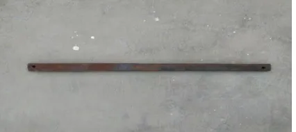
Main arm
Main arm guide link Cutting torch link Front link
Required bolts and nuts 7.1 MAIN ARM
The main arm is fixed to the pillar by the help of welding. The main link is held or supported with the pillar by the help of the main arm. This is made up of mild steel and the shape is rectangular plate. When the guide link is moved manually the cutting torch holding link also moves. The other details and specification are mentioned below. When the guide link moves from one place to another the other links which is welded with the guide link also found to be moving. Bolts and nuts are used to fix the guide link at particular position after settings are made.
Figure 4.1- Main arm
4.2 MAIN ARM GUIDE LINK
The guide link which is made up of EN8 material can be moved along the guide ways, which is found on the main link and it can be fixed at any position. This guide link can be moved in longitudinal direction. This can be moved in either towards cylindrical column or away from the column. When the guide link moves from one place to another the other links which is welded to the guide link is also found to be moving to fix the guide link at one particular position after settings are made.
4.3 FRONT LINK
The front link is moderate mild steel made as rectangular pipe. This front link can be moved in a longitudinal direction. And also in longitudinal manner either towards cylindrical column or away from the column. when the front links moves from one point to another, links which is welded to the front link is also found to be moving. Bolts and nuts are used to fix the front link at one particular position after settings are made. The front link can be moved manually and hence no power is required to move the front link.
Figure 7.2- Front link
4.4 BASE STAND
The base stand is the supportive structure for the entire pantograph cutting machine. It consists of the following components;
Working stand
Tracing needle
Template stand
Cylindrical column
4.5 WORK STAND
[image:3.612.82.295.552.647.2]© 2017, IRJET | Impact Factor value: 4.45 | ISO 9001:2008 Certified Journal
| Page 132
Figure 4.3- Work stand
7.6 TRACING NEEDLE
A hole is drilled in the C-frame and the drilled threaded bush is fixed. This is made up of mild steel material with the grade number EN1A. The purpose of threaded bush is to fix the job holder with the main frame which also acts as a base. Similarly two or more holes are found to be drilled in a C-frame, where the job holder along with the threaded bush can be fixed at any hole which makes the operation easy.
Figure 4.4- Tracing needle
7.7 TEMPLATE STAND
[image:4.612.324.586.247.372.2]A stand is used which is made up of mild steel for supporting the template. This template holder can be raised up or down along vertical column by means of threaded screw. This template stand is found to be fixed in the rectangular frame which is already welded to the base frame.
Figure 4.5- Template stand
7.8 CYLINDRICAL COLUMN
This is in a cylindrical shape, made up of mild steel which is found to be welded at the junction of two C-frames. This cylindrical pillar is the one which supports the main arm. A collar the main link is rigidly fixed in cylindrical collar or pillar. The dimensions of the column vary from top to bottom end. That is the diameter of the pillar is slightly increased from top end to the base end where it has to be welded in the base.
Figure 7.6- Cylindrical column
7.9 TEMPLATES
Template is made up of mild steel. There are various types of templates used. They are square template, elliptical template, circular template, etc. The shape of the template used in this project is rectangular/triangular shaped template. Whatever the shape we required, the tool cut on the plate is grooved on the square template. If we want to cut a square shaped plate then a square template can be used. Similarly elliptical, triangular, circular shapes can be cut by using the tracing needle and the required template.
5. Mechanism of Pantograph
[image:4.612.43.292.533.660.2]The basic form of a pantograph is a four- bar mechanism in the form of parallelogram ABCD, as shown
[image:4.612.350.547.568.656.2]© 2017, IRJET | Impact Factor value: 4.45 | ISO 9001:2008 Certified Journal
| Page 133
It consists of four links AB, BC, CD and DA are pin- connected at A, B, C and D respectively. Link BA is extended to a fixed pin O. Suppose Q is a point on the link AD of which the motion is to be enlarged, then the link BC is extended to P such that O, Q, P are in a straight line.
It may be noted that link BC is parallel and equal to the link AD and link AB is parallel and equal to link CD; thus ABCD is a parallelogram.
When the point Q on the link AD moves to new position Q1 by rotating the link OAB downwards, then A moves to A1, B to B1, C to C1, D to D1 and P to P1. The new configuration of the mechanism thus obtained is shown by a dotted line.
PROOF:
The path of point P describes the enlarged path that of point Q. in other words, the movement of Q (QQ1) is enlarged to PP1 in a definite ratio.
Considering two similar triangles OAQ and OBP, we can write OA/OB = OQ/OP
For a new (dotted) position of the mechanisms also, triangles OA1Q1 and OB1P1 are similar triangles since length of the links remain unchanged.
Now considering two similar triangles OA1Q1 and OB1P1, we can write
OA1/OB1 = OQ1/OP1 But OA1=OA and OB1=OB
OA/OB = OQ/OP = OQ/OP1………(a)
Since triangles OQQ1 and OPP1 are similar, we can write OQ1/OP1 = QQ1/PP1………….(b)
From equations (a) and(b), we get OA/OB = OQ/OP = QQ1/PP1 PP1 = QQ1 x(OP/OQ) PP1 = QQ1x(OB/OA)
It is clear that the point Q describes a path similar to the path described by point O. Also PP1 is a enlarged curve of the actual curve QQ1.
6. DESIGN CALCULATION
A
c B
10m/s O
D E Formula:
Angular velocity = 2πN/60
= 2π*10/60 = 1.04 rad/sec
ADVANTAGE
Less time processing
Simple and easy to operate
No need of skilled labour
It occupies less space
Economical
DISADVANTAGE
Cutting models are limited
APPLICATIONS
An instrument for copying a plane figure to a desired scale, consisting of styluses for tracing and copying mounted on four jointed rods in the form of a parallelogram with extended sides.
A similarly jointed framework, such as a power-collecting trolley on an electric locomotive or an extensible telephone arm.
A mechanical linkage based on parallelograms causing two objects to move in parallel; notably as a drawing aid.
A pattern printed on a document to reduce the ease of photocopying.
A similarly-formed conductive device, now usually Z-shaped, that collects electric current from overhead lines for trains and trams.
An instrument for the mechanical copying of engravings, diagrams, plans, etc., either upon the same scale or upon a reduced or an enlarged scale.
A device made of pairs of perforated arms joined together and used for reducing the cross-head motion of an engine for the purpose of indicating; a reducing motion used in taking indicator-cards of engines and working on the reducing principle of the ordinary pantograph.
© 2017, IRJET | Impact Factor value: 4.45 | ISO 9001:2008 Certified Journal
| Page 134
CONCLUSIONThus in this project the” Pantograph cutting machine” is designed and fabricated. This system is chosen to cut materials in various shapes parallely without any time delay. In existing system each material can be cut in different patterns, using different tool and machines. But in pantograph number of similar patterns can be cut at the same time. And this is simple to operate and it ensures the safety of the operator. The give pattern can be machined according to the required size; it can be either minimized or enlarged. This machine also monitors the dimension of the sample to be made. Since it does all functions such as marking, scaling and cutting parallely it can be used in various industries to cut mild steel. This can also be attached in any cutting machine with slight modification to increase the feed rate and depth of cut. This machine is economical and environment friendly. This can be handled by any individual.
REFERENCES
[1] Nagaraj.B, P.Pandiyan (2009) “KINEMATIC OF PANTOGRAPHMASTS”, International journal of mechanism and machine theory, VOL.44, NO.PP822-834.
[2] Yavin.Y (1998) “THE CONTROL OF MOTION OF A PANTOGRAPH” VOL.28, NO.PP13-23.
[3] R.S.Khurmi, J.K.Gupta (1990) “THE MECHANISM WITH LOWER PAIR” VOL.24, NO.PP232-233.
[4] P.F. Simonet, University of Michigan, School of Dentistry, Ann Arbor, Mich. USA
http://dx.doi.org/10.1016/0022-3913(81)90454-6
[5] Singh, S.K., Chebolu, A., Mandal, S. et al. Prod. Eng. Res. Devel. (2013) 7: 517. doi:10.1007/s11740-013-0479-x
[6] Liang, C., Ceccarelli, M. & Takeda, Y. Front. Mech. Eng. (2012) 7: 357. doi:10.1007/s11465-012-0340-5
[7] https://en.wikipedia.org/wiki/Pantograph
BIOGRAPHIES
R.Vigithra is an Assistant Professor – Grade (1) has more than a decade of teaching experience, received the B.E.