How to cite this paper: Rijab, M.A. and Al-Mosawi, A.I. (2014) Effect of Austempering Time on Microstructure and Wear Resistance of Ductile Iron Castings. Open Access Library Journal, 1: e1032. http://dx.doi.org/10.4236/oalib.1101032
Effect of Austempering Time on
Microstructure and Wear
Resistance of Ductile Iron Castings
Mustafa A. Rijab1, Ali I. Al-Mosawi21Mechanical Department, Technical Institute of Baquba, Baquba, Iraq 2Free Consultation, Hilla, Iraq
Email: aliibrahim76@yahoo.com
Received 28 August 2014; revised 2 October 2014; accepted 6 November 2014 Copyright © 2014 by authors and OALib.
This work is licensed under the Creative Commons Attribution International License (CC BY).
http://creativecommons.org/licenses/by/4.0/
Abstract
An experimental investigation was carried out to study the structure of ductile iron castings which were selected to perform the investigation: 1.4% Ni - 0.3 Mo and 2.4% Ni - 0.3 Mo. After austeni-tizing at 880˚C for 1.3 hr, the two alloys were austempered at 250˚C and 350˚C for time intervals of 60, 120, 240 minutes. Microstructure observation and measurement of UTS, and adhesive wear resistances were reported as functions of austempering time. The results also showed that the obtained structure properties are not believed to be the best possible, but rather they should be viewed as what can be expected with reasonable controls. Production of a conventional spare gear from austempered ductile iron was aimed and concluded at a later stage. The same casting and treat-ing conditions attributed to the optimum structure properties were used for production of the gear.
Keywords
Austempered, Ductile Iron Castings, Microstructure, Wear Resistance
Subject Areas: Industrial Engineering, Mechanical Engineering
1. Introduction
OALibJ | DOI:10.4236/oalib.1101032 2 November 2014 | Volume 1 | e1032 Alloyed ADI is usually used in conditions when increased hardenability is required for casting thick sections. Ni-Mo alloys are expected to provide a strong synergistic hardenability effect with good austemperability [7]. The combination of high strength, toughness and excellent machinability (usually at lower cost than competing materials), is the primary appeal [8]. It offers these superior combinations of properties because it can be cast like any other member of the ductile iron family, thus offering all the production advantages of a conventional ductile iron casting [9]. The attractive mechanical properties inherited from a definite austempering condition are aimed to be selected in order to produce a gear used in automotive application. Nickel was selected because of its favorable distribution within the microstructure, its lack of deleterious compound formation, and austem-perability [10] [11].
2. Materials and Methods
2.1. Materials
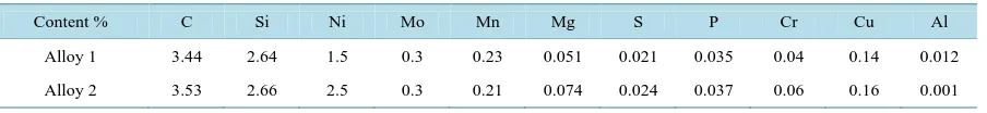
Two ductile iron alloys, having different nickel content, were selected for this study, alloy (1): 1.5% Ni - 0.3 Mo and alloy (2): 2.5% Ni - 0.3 Mo. The chemical compositions of the two alloys are presented in Table 1.
2.2. Samples Preparation
Cylindrical samples of 200 mm length and 20 mm diameter. For more precession and more accuracy of dimen-sions. The melt was then poured at a temperature range of 1300˚C - 1350˚C. Production of some gears with a definitely chemical composition and with an austempering condition that gives certain microstructures proper-ties as required by practical application was included at a later stage of this study.
2.3. Testes
ASTM specification standards were used to determine tensile, impact and wear properties. Conventional spare gears were also cast at a final stage by sand casting method, the chemical analysis of which was the same of that of alloy (1). The adhesive disc was stainless steel, of 60 mm outer diameter and 58 RC hardness. Wear of the specimens was measured by weight loss.
2.4. Heat Treatment Cycles
All heat treatment cycles performed during this study to produce ADI. The heat treatment cycles consisted of two stages: first, specimens were austenitized at 880˚C for 1.25 hr, in a muffle furnace, then austempered from austenitizing temperature to at 250˚C and 350˚C in salt bath (NaNO3 + KNO3). Holding at these temperatures
was for predetermined times, followed by cooling to room temperature in water. The austempering times were selected to be 60, 120, 240 minutes. It is of interest to mention that quenching from austentizing temperature to the salt bath should be rapid enough to avoid any transformation of the austenite to ferrite or pearlite.
2.5. Microstructures Examination
The specimens were etched in 2% nital solution (2% nitric acid + 96% ethylaecohol), examined and photo mi-crographic using universal inverted metallurgical optical microscope.
3. Results and Discussion
The microstructures of cast iron used throughout this work are shown in Figure 1. Figure 1(a) illustrates the microstructure of the as-polished surface for alloy (1), whereas Figure 1(c) depicts the corresponding micro-structure of alloy (2). The micromicro-structures of the as-etched conditions for alloys (1) & (2) are also shown in
Table 1. Chemical composition of ductile irons used for austempering.
Content % C Si Ni Mo Mn Mg S P Cr Cu Al
Alloy 1 3.44 2.64 1.5 0.3 0.23 0.051 0.021 0.035 0.04 0.14 0.012
OALibJ | DOI:10.4236/oalib.1101032 3 November 2014 | Volume 1 | e1032
Figure 1. The microstructure of both alloys (1) & (2), prior to and after etching.
Figure 1(b), Figure 1(d). Comparing Figure 1(a) with that of Figure 1(c) for alloys (1) & (2), it can be con-cluded that the nodule count is significantly higher in Figure 1(c) as compared to Figure 1(a). Such increase is fairly inherited from the potent role of Ni in enhancing the graphitization process (3% in alloy vs. 2.5% in alloy 1). The as polished structures in both Figure 1(a) and Figure 1(c) indicated that there might have been a slight inhomogeneity of Ni which reflects some non-homogeneous distribution of graphite particles (nodules) into a ferritic/pearlitic matrix.
From Figure 1(b), Figure 1(d) it is noticed that the amount of ferrite in the matrix of alloy (2) is significantly larger than in alloy (1), whereas alloy (1) contains mainly a pearlitic matrix along with little amount of ferrite areas around graphite nodules. The morphology of ferrite is in the form of bull-eye structure resulting from se-gregation of silicon and/or nickel around graphite nodule in the microstructure of alloy (1) Figure 1(b). The mi-crostructures of ADI depend on significant variables among which are: base chemistry alloying additions and heat treatment [4] [5].
The microstructures of ductile irons austempered at 250˚C for different austempering time intervals corres-ponding to 30, 60, 120 and 240 minutes for alloys (1) & (2) are shown in Figure 2. As can be seen, the matrices for alloys (1) & (2) consist mainly of martensitic and lower bainite. Retained austenite might not be expected. This is due to insufficient diffusion of carbon to the austenite to stabilize it, thus martensite may form during rapid cooling to room temperature and retained austenite might be slightly expected after 30 minutes, austem-pering time [3] [7]. As the austempering time increases, the amount of martensite in the matrix decreases. In contrast, the amount of retained austenite might increase until a critical point.
Such critical austempering time provides the best combination of strength and ductility. On the other hand, extended austempering time tends to enhance the bainitic transformation and hence, the amount of retained aus-tenite decreases subsequently with increasing the austempering time until a definite point i.e. the onset of second stage austempering [9]. The presence of carbides is not beneficial in ADI since they are inferior to ductility and impact toughness. This type of bainitic structure is found in Figure 2 and may provide ADI with higher strength and a relatively lower elongation [2] corresponding to ASTM standard grades [10].
The microstructures of ductile irons austempered at 350˚C for different austempering time intervals are shown in Figure 3. The matrix structure is expected to comprise upper bainite, retained austenite, and martensite. The apparent amount of transformed upper bainite increases by increasing the austempering time. At shorter aus-tempering time, untransformed austenite formed martensite by subsequent quenching. With longer ausaus-tempering time, martensite disappeared due to the increased stability of the untransformed austenite, which is enriched by carbon. This carbon is rejected from ferrite due to the high silicon content of the ductile cast iron. The formation of carbides will be suppressed. A similar result was reported in other findings. This treatment provides also high strength and higher elongation corresponding to ASTM standard specifications [6]. At short austempering time, the martensite was observed for alloys (2) & (1) until 30.
OALibJ | DOI:10.4236/oalib.1101032 4 November 2014 | Volume 1 | e1032
Figure 2. Microstructure change of ductile iron austempered at 250˚C for dif-ferent austempering time intervals, upon austenitizing at 880˚C for 60 min, 500×.
Figure 3. Microstructure change of ductile iron austempered at 350˚C for
dif-ferent austempering time intervals, upon austenitizing at 880˚C for 60 min., 500×.
Table 2. Relative wear resistance of ADI gears.
Wear properties G2 G1
Steel ADI Steel ADI
Original weight 241 211 310 297
Weight after loading for 120 hr on the machine - 207 - 289
OALibJ | DOI:10.4236/oalib.1101032 5 November 2014 | Volume 1 | e1032 pering temperatures is the critical austempering time after which the weight loss reaches a minimal steady state (60 - 120 min at 350˚C & 240 min at 250˚C) for alloy (1) and (120 - 240 min at 250˚C & 60 - 120 min at 350˚C) for alloy (2). The wear resistance of ADI is explained in view of both microstructural of the alloys after austem-pering. However, it is interesting to notice that the peaks in weight loss are associated in the peaks of the elonga-tion percentage curve.
4. Conclusion
Austempering treatment at 250˚C fulfills the production of ADI of high strength, while austempering at 350˚C produces ADI with high ductility. Austempering at 350˚C for Ni-Mo alloyed ductile irons produces probably due to molybdenum segregation in cell and/or grain boundaries. The emergence of multi-peaks upon austem-pering of Ni-Mo alloyed ductile iron is a point that needs much more investigation.
References
[1] Hughes, I.C.H. (1998) Ductile Iron. ASM Handbook: Casting, Vol. 15, ASM International, Materials Park, 647-666.
[2] Massone, J.M., Boeri, R.E. and Sikora, J.A. (1996) Decomposition of High Carbon Austenite in ADI. AFS Transac-tions, 133-137.
[3] Ductile Iron Society (2001) Ductile Iron Data for Design Engineers.
[4] Eid, M.R. (2001) Effect of Graphite Nodularity on Structure and Mechanical Properties of Austempered Cast Iron. M.Sc. Thesis, Cairo University, Cairo.
[5] Abd Elhakeem, A.A. (2002) Austempering of Spheroidal Graphite Cast Iron. M.Sc. Thesis, Cairo University, Cairo.
[6] Forrest, R.D. (2000) Austempered Ductile Iron for Both Strength and Toughness Part II. Machine Design, 134-146.
[7] Elliott, R. (2004) Austempering of an Mn-Mo-Cu Alloyed Ductile Iron Part 1—Austempering Kinetics and Processing Window Part II. Materials Science and Technology, 12, 233-248.
[8] Gundlach (2006) Monitoring the Bainite Reaction during Austempering of Ductile Iron and High Silicon Cast Steel by Resistivity Measurement Part III. AFS Transactions, 32, 17-24.
[9] Young, J.M. (2008) Influence of Austempering Temperature on the Characteristics of Austempered Ductile Iron Al-loyed with Cu and Ni. AFS Transactions, 43, 113-122.
[10] Morton, P.A. (2009) A Guide to Mechanical Properties Possible by Austempering 1.5% Ni - 0.3% Mo Ductile Iron Part II. AFS Transactions, 67, 78-93.