© 2016, IRJET | Impact Factor value: 4.45 | ISO 9001:2008 Certified Journal | Page 671
“AUTOMATION IN AIRCRAFT”
Shripad Shashikant Chopade, M Tech (Machine Design & Robotics), UPSC (IES), Indian Railway Service of Mechanical Engineers, Government of India, Ph.D Research Scholar, India
shripadschopade@gmail.com, shripadiesofficer@gmail.com
---***---ABSTRACT:
The cooling coils have wide range ofapplications in the field of refrigeration and air
conditioning. The cooling coils performance depends
mainly on its maintenance. The optimum performance
result depends on various factors such as velocity of the
flow primary surface area, number of tubes, fins spacing
etc. The application also depends upon the number of
rows of cooling coils. The cooling coils used in condensers
are normally used for heat rejection. A fresh air
application requires maximum 8 rows of the coils.
Variations in any of the design factor may also affect the
performance of the coil.
Keywords: Compressor, Direct expansion Evaporator,
Feeder Pipes, Flooded Evaporators, Flow of Refrigerant,
Thermostatic Expansion Valves.
I INTRODUCTION
The air cooling coil with direct expansion uses a
thermostatic expansion valve and these coils are used in
the majority of comfort air conditioning applications,
mostly below 100 tons capacity. If we look at the basic
refrigeration cycle and the part played by the evaporator,
the function of an evaporator is to take the heat into the
system from the surrounding atmosphere. The
refrigeration entering in the coil is a low pressure low
temperature mixture of a saturated liquid and vapour. As
refrigerant mixture gradually travels towards the outlet of
the coil, the liquid while absorbing the heat gases
converted in to vapour and at outlet the entire refrigerant
is in the form of superheated gases.
II CONDITION FOR OPTIMUM PERFORMANCE
2.1 Factors to Be Ensured For Optimum Performance
In order to get maximum performance from the
cooling coil we try to ensure that maximum proportion of
liquid enters the evaporator inlet with minimum
proportion of vapour. This is essential because it is latent
heat while converting the liquid refrigerant into vapour,
absorbs a large amount heat from the surrounding. Heat
absorbed the vapour is insignificant. The proportion of
liquid to vapour increase can be ensured by sub cooling
the liquid before it enters the expansion valve so that at
the evaporator less flash gas is formed.
2.2 Factors under Designers Control
The general equation of coil capacity is
Q = U x A x ΔT
U = Over all heat transfer coefficient.
A = Coil surface area
Some of the factors that influences coil design are as
follows
Tube diameter – 5/8”, ½”, 3/8”, or 7 mm
Tube spacing and the arrangement
© 2016, IRJET | Impact Factor value: 4.45 | ISO 9001:2008 Certified Journal | Page 672
Fin thickness, fin material, configuration
either plain/ corrugated or slotted etc.
2.3 Measures to Reduce Heat Transfer Resistance
The main objective of the designer is to reduce the
resistance to heat transfer and can be achieved by
Increasing heat transfer coefficient on air side
by increasing the ratio of external to internal
area or by increasing air side heat transfer
coefficient.
Increasing the air velocity over the coil.
III
Factors controlling the performance
[image:2.595.342.542.175.449.2]3.1 Effect of Air Velocity Increase on Capacity
Fig 1 Effect of Air Velocity Increase
The above figure indicates that as the velocity of
air increase the coil capacity increases. However the rate
of increase is less at higher face velocities as can be seen
from the reduced slope of coil performance coil. We know
that increasing velocity means more air quantity (Cfm). So
we take both the results into account i.e. coil
performance and fan performance to assess the net
result.
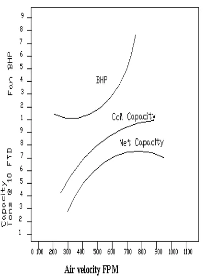
3.2 Overall Performance of Fan and Coil Combination
Fig 2 Overall Performances of Fan and Coil Combination
The fan laws indicate that the fan horse power
increases as the cube of velocity increases. As shown in
the above figure after a particular velocity the net heat
effect in fact is a capacity loss, since the motor heat input
more than offset the gain in coil capacity.
3.3 Effect of Increasing Heat Transfer area
Increasing the external surface area is the most
common approach to improving coil performance. Once
the tube is selected the internal area gets fixed where as
external area can be increased by adding fins of various
designs and increasing the number of fins per unit length.
[image:2.595.41.283.398.590.2]© 2016, IRJET | Impact Factor value: 4.45 | ISO 9001:2008 Certified Journal | Page 673 secondary to primary surface area increase the
effectiveness per square foot area decreases conversely
lower the ratio for the required performance the more
effective the surface per square foot of area. While
comparing coils of difference manufacturers one should
check the primary area provided and not the total surface
area because more primary area of coil will provide more
efficient coil.
[image:3.595.354.565.186.318.2]3.4 Effect of using Small Diameter Tube
Fig 3 Effect of using Small Diameter Tube
More compact tube arrangement.
Higher pressure drop
Smaller tube diameter
More fan power
Lower secondary to primary area
As shown in above figure more primary area
available face area is possible by reducing the tube
diameter and packing the tubes more compactly. (Lower
secondary to primary area ratio). The drawback is only
that more the compact coil higher is the air side pressure
drop, resulting in more fan power to deliver the same air
quantity.
3.5 Effect of Increasing Number of Rows
Fig 4 Effect of Increasing Number of Rows
As the number of rows of coil increases for a same
area or the coil is deeper lower will be the air leaving the
temperature and moisture content. The refrigeration
capacity also increases. It can be seen from the above
figure that each successive row of tubes is less efficient
and less effective. This means less moisture removal or
temperature drop is expected from 5th or 6th row
compared to 1st or 2nd row. The greatest rate of heat
transfer is where the air is entering the coil since at entry
condition, the moisture content and temperature is
highest as the air temperature curve approaches the
saturation line the curve becomes steeper indicating that
the ratio of moisture removal to temperature drop is
greatest at the last row or at the exit of the coil. Such coil
designs with more rows are used in cold rooms, blast
freezers, or in low temperature application. Coils with a
large face area and lower number of rows with very high
air quantities are preferred for the application where we
[image:3.595.64.248.312.500.2]© 2016, IRJET | Impact Factor value: 4.45 | ISO 9001:2008 Certified Journal | Page 674 grape storage room where humidity needs to be
maintained to prevent weight loss.
[image:4.595.48.247.172.319.2]3.6 Effect of Fin Spacing
Fig 5 Effect of Fin Spacing
Closer fin spacing also lowers the coil condition
curve as shown in the above fig. similar to one with face
area increases. However closer fins means a higher
pressure drop across a coil, resulting in decrease in air
quantity or increase in fan horse power for the same air
quantity. In case of coils used for low temperature
application the defrosting becomes difficult if the coils
have closer fin spacing.
3.7 Effect of Increase in Air Flow
Fig 6 Effect of Increase in Air Flow
Higher air flow will raises the coil condition curve
which means the air outlet temperature will be higher to
compare to the coil subjected to a lower air flow. The
refrigeration capacity however increases because of air
flow rate increases in greater proportion than decrease in
enthalpy.
Q α Cfm x ΔH.
Where ΔH = the enthalpy difference.
By increasing air flow the heat removal will be
faster and the temperature will be more uniform in the
conditioned space. Increasing air quantity will however
mean a higher fan power as well as higher noise level.
[image:4.595.47.273.561.718.2]© 2016, IRJET | Impact Factor value: 4.45 | ISO 9001:2008 Certified Journal | Page 675
Fig 7 Effect on By Pass Factor
The design of coil also affects B.P Factor. As the air
travels over the coil, if it remains in contact with the coil
for longer duration, the bypass factor reduces, which
mean the supply air condition never to the saturation
line. As the air leaving the coil is nearer to be saturated
line the required air quantity reduces. It also means that
the supply air temperature it lower and air leaves in drier
condition as more moisture is removed from it. While
estimating cooling loads and air quantity we have to
assume certain by pass factor which depends upon the
coil configuration.
IV BY PASS FACTOR
4.1 By Pass Factor for Varying Load Depth
Table 1 By Pass Factor for Varying Coil Depth
From the analysis of the above table following conclusion
can be drawn.
As the fin density increases, there is more resistance
for air to travel and by pass factor reduces.
As the number of row increases the air remains in
contact for a longer duration leading to a lower
bypass factor.
As the velocity increases, since the air passes through
the coil faster, the bypass factor. If we reduce the
velocity below a particular point, the chance of coil
freezing increases
If the velocity increased beyond a point, the increased
fan horse power neutralizes the gains in capacity,
which has been demonstrated. Depth of
coil
(rows)
8 fins per
inch velocity
300-700
fpm
14 fins per inch
velocity 300-700
fpm
2 0.42-0.55 0.22-0.38
3 0.27-0.40 0.10-0.23
4 0.15-0.28 0.05-0.14
5 0.10-0.22 0.03-.09
6 0.06-0.15 0.01-0.05
[image:5.595.69.268.131.265.2]© 2016, IRJET | Impact Factor value: 4.45 | ISO 9001:2008 Certified Journal | Page 676
V MAINTENANCE OF COOLING COILS
5.1 Necessity for Keeping the Coils Clean
The coils do get dirty. In fact, in humid climates
particularly coils not only gets dirty, but they become
home to fungi, slime and all types of microorganism.
Justin Salmon said that ‘Dirty coils are like termites’. It is
not a matter of if you will get them but it’s more a matter
of when and how severe.
5.2 Way to Keep the Coil Clean
It is of course, best to start with a clean coil. As the
part of commissioning process clean the coil to remove
the construction dirt. Then begin a regular schedule of
cleaning at least twice year. The most important thing is
the maintenance staff can do to ensures years of trouble
free coil operation is to use ASHRAE 60 percent efficient
filters and change them frequently. Filters are cheap and
will intercept most of the dirt and fungal spore before
they get to the coil. Proper filtration may even decrease
the need to clean a coil. To ensure the cleanliness inspect
the coil on regular basis.
How does Dirty Coil Increases the Cost of Coil
We should know that the dirty coil is an inefficient
coil. It increases the cost by decreasing the efficiency of
the two factors. The first is fan power lost due to
increased static pressure loss through the coil. Reduction
in capacity caused by the layer of dirt bio logical growth
coating heat transfer surfaces.
Frequency of Cleaning the Coils
The state of Minnesota recommends the cleaning of
the coil twice in a year whether the coil looks dirty or not
in fact, if a coil looks dirty then it may be too late to clean
effectively.
VI COIL CONSTRUCTION
6.1 Chilled Water Coil Construction
In the above coil shown the tubes used are of copper
and are arranged parallel to one another either in
staggered or non staggered pattern, along the length ‘L’
of coil a staggered pattern is commonly used. Plate or
ripple fins are used to enhance the heat transfer area.
Thus primary surface area is enhanced greatly by adding a
secondary area of fins the total area including fin is called
as ‘Outside surface area’ for use in the calculations. The
cross section (L x H) across which air flow is called the face
surface area or the finned area. Thus L is finned length
and H is finned height. Fins are arranged perpendicular to
the tubes. Fin spacing varies between 8 and 14 fins per
inch of tube. Average air velocity across the face area is
called coil face velocity or simply faces velocity. Thus,
Face velocity (fpm) = Dehumidification air flows (cfm)
Face area (sq. ft)
The number of rows of copper tubes in the direction
of air flow is termed as depth of coil. Coils with 3, 4, 6 or 8
rows are commonly used. Refrigerant or chilled water
enters the first row and leaves the coil from the last row.
A coil in which chilled water or refrigerant is supplied to
all the tubes in the first row (also referred to as tubes high
© 2016, IRJET | Impact Factor value: 4.45 | ISO 9001:2008 Certified Journal | Page 677 the supply is given to alternate tubes in face we get a half
circuit coil.
6.2 Final Coil Selection Procedure
For sizing the coil the following data is required from the
heat load calculations.
Room DB temperature (f)
Fresh air DB temperature (f)
Dehumidification air quantity (cfm)
Fresh air quantity (cfm)
Grand sensible heat factor(GSHF)
A.C load (ton)
Apparatus dew point (ADP) (f). This denotes average
outside surface temperature of the coil.
VII COILS AND THEIR APPLICATION
7.1 Direct Expansion Coil
The two direct expansion coils is generally used for
light loaded jobs. Minimum latent load and a high
air volume.
3 and 4 coils are frequently used for air
conditioning applications
5 row coils for large latent load.
6 row coils are used for applications with stringent
controls on relative humidity.
8 row coils are used for 100% fresh air circulation.
7.2 Chilled Water Coils
For normal air conditioning application 3,4, or 5 row
coils are used
6 row coil for application involving high outside air.
8 row coil for 100 % fresh air application.
7.3 Condenser Coil
In normal air conditioning these are used for heat
rejection.
VIII CONDENSATE TRAPS FOR COOLING COILS
The condensate trap perhaps is a most overlooked
item in the design and the installation of fan coils and air
handlers with cooling coils often condensate traps are
inadequately described in contract do comments and
sometimes are not described at all which levels important
details to be determined by the installing contractor.
There are wide misconceptions about how condensate
traps work and how to properly size them. Little or no
though is devoted to simple, inexpensive details that can
make them such easier to inspect and maintain.
8.1 Review
The purpose of one of these traps is to allow
accumulating condensate to drain off while preventing air
from entering draw thru unitor escaping a blow thru unit.
A cooling coils drain pan opening is located at the point in
an air flow system where the air pressure either positive
or negative is the greatest. It makes sense to prevent an
air “leak” at this location, especially in view of the effort
we typically expend to seal and pressure test system duct
work. In short the fundamental purpose of one of these
traps is to use a column of condensate in such a way as to
prevent air movement in to or out of the equipment
© 2016, IRJET | Impact Factor value: 4.45 | ISO 9001:2008 Certified Journal | Page 678
8.2 Potential Problems
An improperly constructed or missing trap can cause the
following problems
No Trap or Trap Outlet is too Low For draw thru units in
either of these situations; condensate accumulating in the
pan will be subjected to a “jet” of incoming air, which
often results in spray being carried over into the fan inlet
area. This sometimes is referred to as “geysering” for
blow thru units, escaping air may be the most serious
consequence, but in the presence of copies consideration,
a turbulent air/ water mix in pan also may cause some
spillage as spraying of water downstream of the coil.
Trap Outlet too High In draw thru units with this problem
an air seal will be maintained, however if the condensate
net “Column” height in the trap is less than the
equipments negative air pressure in inches of water
column, the condensate will be unable to drain away. This
will cause the accumulating condensate to overflow the
pan into the surrounding part of the equipment casing. In
a blow thru unit, an outlet as high as the inlet will work
during fan operation as high as the inlet will work during
fan operation as long as the rest of the trap is properly
dimensioned.
One Trap Shared by Two or More Fan Coil Units If one of
the fan coil units sharing a trap is shut down, the other
will blow air into or draw air from the inactive system,
depending on whether the units are of the draw thru or
blow thru variety. For this reason each fan coil unit should
have its own trap.
Dry Trap A common problem in very arid climates and
during periods when cooling coils are inactive such as
winter, in evaporation of the water in traps. A liquid seal
can be maintained by either continues drip or
intermittent trap “Priming”. Designers are uncertain
whether or not evaporation occurs or who anticipate that
it does should specify either a means of priming or trap
features that will allow priming to be easily added later. A
dry trap on a draw thru unit can be the sources of the
object ional odors and noxious fumes in a building ( At a
military air base in the desert a draw thru air handless
was located near a flight line. While the unit fresh air
intake was located near a flight line. While the unit fresh
air intake was located well away from any sources of
contaminated air, the flow drain for the trap was not and
building occupants were sickened by the fumes or burn
jet fuel inducted through the dry trap. Priming the trap
solved the problem). Priming water should be applied to
the downstream side of the trapped care should be taken
to assure adherence to plumbing codes regarding air gaps
for protecting portable water sources.
Draw Thru Traps The necessary dimension of a trap on a
draw thru unit and the maximum level of condensate that
can exist in such a trap with the fan off. The
recommended safety factor of 1 in. added to the casing
pressure in a reasonable balance between the need to
account for unanticipated increase in that (negative
pressure and the practical need to keep the total trap
depth (L) to a minimum especially on pad mounted
equipment. Many traps are improperly installed because
dimension “L” was not taken into account in mounting
© 2016, IRJET | Impact Factor value: 4.45 | ISO 9001:2008 Certified Journal | Page 679
Blow Thru Traps The fig. shows the required dimensions
of traps on blow thru units and maximum level of
condensate that can exit in such a trap with the fan off.
Here again 1 in. safety factor is a practical
recommendation for accounting for an increase in casing
pressure caused beyond the situation by the designers
control. In most system 1 in. of water gauge is a
significant percentage of the casing air pressure. Of
course the designer can increased the calculated
equipment pressure as necessary.
8.3 Recommendation
A trap with two tees and plugs allows easy access
for inspection cleaning and if necessary, priming.
Although the plugs can be wrench tight, a hand tight
condition usually prevents air leakage on the inlet side,
and one does not have to have a wrench to inspect the
trap. The purpose of the plug on the outlet side is to keep
dirt small animals, and insect out of the trap. Traps
commonly are constructed of either copper or plastic
pipe. Under the pressure of design deadlines, it often is
difficult to pay attention to detail that all project deserve.
In the matter of condensate traps, however, a couple of
simple standard drawings in a designers CADD repertoire,
with fill in the blank dimensions, will go a long way
towards demonstrating completeness of design and
preventing problem.
IX CONCLUSION
The increase in air flow will increase the
refrigeration capacity of the cooling coils. Closer fins leads
to higher pressure drop which result in decrease in air
quantity and increase in fan H.P for same quantity of air.
Increase in number of rows of coil increases the
refrigeration capacity. More is the compact coil higher is
the air side pressure drop, resulting in more fan power to
deliver the same air quantity. Proper maintenance of the
coil within the regular interval of time also reduces the
cost of the coil. Increase in heat transfer area improves
the coil performance.
REFERENCES
[1] www.Msifla.com
[2]Service clinic coil cleaning By Dillard W. M. and
Salmon J.S.
[3]Voltas Engineers (Handbook)
[4]Blue stars engineers (Handbook)
[5]Air- conditioning and refrigeration journal (July Sept
2003) Page 78-82
[6]Air- conditioning and refrigeration Journal (Oct-Dec
2002) Page 75-79, Page 90-92
BIOGRAPHIES