© 2017, IRJET | Impact Factor value: 5.181 | ISO 9001:2008 Certified Journal | Page 1312
Improving Efficiency of Submersible Pump Impeller of Mixed Flow
Type by Design Modification through CFD Analysis
Naveen Nagalinga Lohar
1, Prof. S A Janawade
2.
1
Department of Mechanical Engineering (M.Tech in Design Engineering)
KLE Dr. M S Sheshgiri College of Engineering and Technology Udyambag, Belagavi, Karnataka, India 590008
2
Department of Mechanical Engineering (Professor)
KLE Dr. M S Sheshgiri College of Engineering and Technology Udyambag, Belagavi, Karnataka, India 590008
---***---Abstract -
Subject of this dissertation work is based on mixed flow pump. Mixed flow pumps have wide range of applications in fields like agricultural irrigation, flood control etc, and also in domestic utilities. But losses occurred inside pump reduces efficiency of mixed flow pump and they also consume large electricity. So by increasing efficiency of pump for the same energy consumption, energy can be saved. So to improve performance of mixed flow pump work is carried out at design level and parameters affecting design and performance of pump are identified. Then to improve efficiency of pump, first analytical designing is done for new improved efficiency pump impeller. These analytical solutions are then used to model the new improved impeller. In ANSYS Blade Modeller’s Vista CPD under ANSYS Workbench 1D model is created. Solid model of impeller is done using ANSYS BladeGen. CFD analysis is carried out in ANSYS CFX. The results of CFD analysis of improved efficiency impeller is compared with analytical solutions, for justification of results which shows close match between both results. Then the results of improved efficiency impeller are compared with existing pump impeller and it is found that by changing inlet and exit angles of impeller blade, reducing number of blades and backward curved vanes improve pump performance significantly.Key Words: Mixed flow pump impeller. Efficiency. Pump parameters, CFD analysis, ANSYS CFX.
1. INTRODUCTION
Pump is a device that uses mechanical energy to move the fluid. Pumps play a very important part in many domestic and industrial applications. Different types of pumps are used in many applications. Pumps are classified mainly into 3 categories based the method they use for lifting fluid and they are gravity, direct lift and displacement pumps. Depending on the configuration of impeller and specific speed pumps are classified as radial, mixed and axial flow pump. Pumps work either rotary or reciprocating mechanism.
1.1.
BROAD VIEW OF PUMPS
Broadly pumps are classified into two types according to their operating method and they are dynamic pumps and positive displacement pumps. A positive displacement pump makes liquid move by trapping a fixed quantity of liquid and driving that volume of liquid into exit pipe. They are also called steady flow pumps.
In dynamic pumps by increasing the velocity of flow kinetic energy is transferred to the liquid, so these are called velocity type pumps. Dynamic pumps are classified into 3 types and they are axial flow pump, radial flow pumps and mixed flow pumps. Radial flow pumps are centrifugal pumps and in these pumps fluid leaves the impeller in radial direction and enters the pump at the centre. In axial flow pumps fluid particles do not change their path because at the entry and exit change in radius is very small.
Mixed flow pumps (MF pumps) are used in large scale among different types of pumps available. In these pumps head is partly developed partly by centrifugal action and partly by bane lift. In these pumps liquid enters axially and leaves in radial way. Impeller is an important part of a submersible pump and pump performance depends on geometry of impeller. Pump performance can be improved by changing the parameters of the pump. Produced liquids, after being subjected to great centrifugal forces caused by the high rotational speed of the impeller, lose their kinetic energy in the diffuser where a conversion of kinetic to pressure energy takes place. This is the mechanism of radial and mixed flow pumps.
2. PROBLEM IDENTIFICATION AND OBJECTIVES
© 2017, IRJET | Impact Factor value: 5.181 | ISO 9001:2008 Certified Journal | Page 1313
Table -2.1: Existing impeller data
Quantity(symbol) Value Unit
Head(H) 46 Meter
Discharge(Q) 0.0078 m3/sec
Rotational speed(n) 2880 Rpm
No of stages(m) 6 No
2.1. Objectives
Designing mixed flow impeller using ANSYS B lade design module.
To use CFD software in designing impeller. To make comparison between analytical and CFD
solutions.
To check the effect of design parameters on head and efficiency by CFD analysis
3. DESIGN OF IMPELLER
3.1 Design of Impeller Layout Profile
Specific speed selection has to be done in U.S. customary units for selection of new impeller by using existing impeller parameters.
From the above equation value of N comes out to be 2527.72rpm.
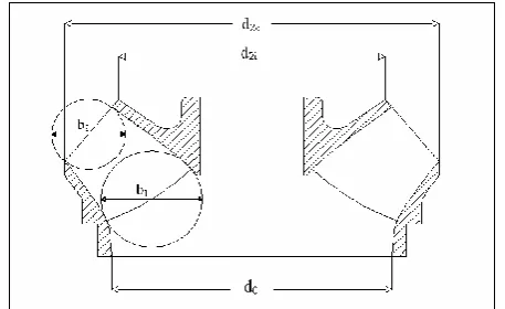
Figure 3.1. Selected impeller layout profile from Layne Bowler Library
For above value of N(u s), we get Δhigh = 3.2 and Δlow= 3.8 as
[image:2.595.313.553.379.487.2]shown in figure 3.2 of Cordier diagram.
Figure 3.2. Cordier Diagram for Δ value selection.
From above equation by putting values of Δlow and Δhigh we
get d2m-low =109.49mm and d2m-high =92.205mm and d2m-avg
=100.85mm.
Ratio d2m / d2o=0.92 and d2o=109.69mm and d2i= 91.25mm
from below figure.
Figure 3.3 d2m/d2o ratio design chart
Then shaft diameter is found by using,
But power transmitted Pm is given by,
By taking n=2880 rpm, =40 MPa, and Pm=906.13 hp ds=18mm.
[image:2.595.47.276.527.667.2]© 2017, IRJET | Impact Factor value: 5.181 | ISO 9001:2008 Certified Journal | Page 1314 Ko value is between 4 to 4.5. for better efficiency take it
near to 4. So value of do= 55.75mm
The volumetric and mechanical efficiencies are taken as 96% for the pump to be designed. The pump efficiency is taken as 76% we can find hydraulic efficiency from the equation below
Using the volumetric efficiency, 𝜂v and the design point flow
rate Q, the flow rate Qi can be calculated by using equation below,
Qi=0.0085 m3/sec
A0, net area in the impeller inlet eye, is given by,
A0 value is 2186.59mm2
Inlet blade angle β1=250 and outlet blade angle β2=180
[image:3.595.320.550.58.268.2]Geometrical values obtained from analytical calculation are listed below
Table 3.1: Geometrical parameters obtained from analytical design of the impeller
Quantity Symbol Value Unit
Shaft Diameter ds 18 Mm
Hub Diameter dh 25.2 Mm
Inlet Diameter D2i 91.25 Mm
Outlet Diameter D20 109.6 Mm
Blade Inlet Angle β1 25 Degree
Blade Outlet Angle β2 18 Degree
3.2. Modeling of Impeller
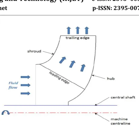
[image:3.595.308.578.307.482.2]Solid modelling of the impeller is done using Ansys blade modeller available under Ansys workbench component system Vista CPD. By giving parameters like input and output angle ,tip diameter meridional impeller graphic sketch is available as in below diagram.
Figure 3.4 Meridional Sketch of the Impeller
Figure 3.5 Blade modelling in VISTA CPD
[image:3.595.29.288.498.646.2] [image:3.595.309.583.518.698.2]© 2017, IRJET | Impact Factor value: 5.181 | ISO 9001:2008 Certified Journal | Page 1315
4. ANALYSIS OF IMPELLER
4.1. Analysis of Pump Impeller
It follows the following steps.
4.1.1. Solid Modeling
[image:4.595.61.262.232.443.2]Solid model of the impeller blade is done using ANSYS Bladegen module, and it is shown in Figure 4.1
Figure 4.1 Solid Model of Impeller from ANSYS Bladegen
4.1.2. Meshing
Geometry has to be broken up into small, manageable pieces called elements. The corner of each element is called a node, and it is at each node that a calculation is performed. All together these elements and nodes comprise the mesh. The pump impeller meshing is carried out using a ANSYS TurboGrid Meshing tool as shown in the figure 4.2.
Figure 4.2 Meshing of Impeller using ANSYS TurboGrid.
4.1.3. Material Selection
Volume inside the suction intake, lower and upper extensions are assigned to water and impeller is treated as solid material and torque calculation is done. Impeller surrounding volume is taken as rotating, and speed and axial rotation are mentioned.
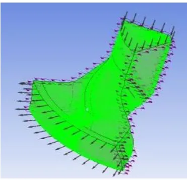
4.1.4. Definition of Boundary Condition
[image:4.595.340.526.296.474.2]At inlet and outlet rise in pressure is determined in analysis. At inlet I atm. Pressure is defined and at outlet volumetric flow rate is defined to determine rise in pressure. Fluid domain is selected in CFX pre basic with material properties of water and shear stress model. After this solver control is defined with 1000 number of iterations.
Figure 4.3 Definition of Boundary Conditions using CFX
4.1.5. Analysis Setup
Software automatically selects incompressible when material assigned is water to volume.
4.1.6 Analysis of Pump
CFD analysis results are available at results post. Pressure and velocity are determined across hub and shroud. To found the hydraulic efficiency torque is utilized and head also found as below.
Head is given by below equation,
The values of Vf1 and Vf2 are determined by velocity triangles
and Vf1= 6.416m/sec and Vf2= 13.2 and U2=16.53m/sec and
=18 degree and g= 9.81m/sec. then value of head becomes H=8.98m/sec= 9m/sec.
[image:4.595.38.286.586.744.2]© 2017, IRJET | Impact Factor value: 5.181 | ISO 9001:2008 Certified Journal | Page 1316 Where =301.59 rad/sec, =16.24Nm, m=6, =1000kg/m3
and H=9.
Therefore hydraulic efficiency =87.87%.
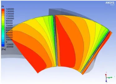
The values obtained from CFD analysis are as shown below.
[image:5.595.342.525.99.281.2]Figure 4.4 Contour of Mass Averaged Pt on Meridional Surface
Figure 4.5 Contour of Mass Averaged W on Meridional Surface
[image:5.595.68.255.208.344.2]Figure 4.6 Contour of Pt at blade LE
[image:5.595.341.526.316.477.2]Figure 4.7 Contour of W at Blade LE
Figure 4.8 Velocity Streamlines at Blade TE
Table 4.1: CFD Results of pump parameters
Head developed 9.60 M
Discharge 0.008125 m3/s
Hydraulic
efficiency 93.68 %
Total efficiency 86.67 %
Shaft power 2127.46 W
[image:5.595.66.257.392.534.2] [image:5.595.67.254.584.719.2]© 2017, IRJET | Impact Factor value: 5.181 | ISO 9001:2008 Certified Journal | Page 1317
Table 4.2: Comparisons of CFD and analytical results
Paramete r
Analytical calculations CFD results
Existing
design design New Existing design design New
Head 7.45
m/stage
9
m/stage
8.12
m/stage
9.60
m/stage
Hydraulic
efficiency 65% 87.87% 67.1% 93.68%
5. RESULTS AND CONCLUSION
From table 4.2 i.e. the comparison between CFD and analytical results of existing and new designed impeller we can conclude that,
1) Head is increased from 8.12 m/stage to 9.60 m/stage in CFD results, 7.45 m/stage to 9 m/stage in analytical results. 2) Hydraulic efficiency is also increased from 67.1% to 93.68%.in CFD and in analytical results also increased from 65% to 87.87%.
From these points (1) and (2) it can be concluded that, the overall efficiency of the newly designed pump is increased compared to existing pump.
REFERENCES
[1] V.G Chhanya, P.J Thoriya , “Design And CFD Analysis Of Submersible Pump Impeller Of Mixed Flow Type For Performance Improvement”, International Journal of Advance Engineering and Research Development, Volume 2, Issue 6, June -2015, e-ISSN(O): 2348-4470p-ISSN(P): 2348-6406, pp. 468-475.
[2] Suresh Pittala, Diriba T, “Computational Fluid Dynamics Analysis of Impeller Design For A Pump”, International Journal of Mechanical Engineering (IJME), Vol. 5, Issue 4, ISSN(P): 2319-2240; ISSN(E): 2319-2259: Jun - Jul 2016; pp. 63-74.
[3] Hao Bing, Shuliang Cao, “Three-dimensional design method for mixed-flow pump blades with controllable blade wrap angle”, Proceedings of the Institution of Mechanical Engineers, Part A: Journal of Power and Energy 2013 227: 567 originally, DOI: 10.1177/0957650913489296
[4] Jidong Li, Yongzhong Zeng, “Optimum Design on Impeller Blade of Mixed Flow Pump Based on CFD”, Procedia Engineering 31, 2012, pp. 187-195.
[5] Micha N l Varchola, Peter Hlbocan, “Geometry Design of