http://dx.doi.org/10.4236/epe.2015.73006
Analysis of the Harmonic Response of
a Modulation Permanent Magnetic
Transmission Equipment Based on ANSYS
Zhiping Zeng1, Jun Li1, Shiyi Zhang2, Yintao Hong1, Yaohong Wang1
1School of Mechatronics & Automotive Engineering, Chongqing Jiaotong University, Chongqing, China 2School of Marine Navigation, Chongqing Jiaotong University, Chongqing, China
Email: [email protected]
Received 21February 2015; accepted 10March 2015; published 16March 2015
Copyright © 2015 by authors and Scientific Research Publishing Inc.
This work is licensed under the Creative Commons Attribution International License (CC BY). http://creativecommons.org/licenses/by/4.0/
Abstract
This paper analyzes the structure and transmission principles of a modulation permanent magnet gear transmission. Its 3D data model is built based on the known optimized parameters from re-search team. Its structure of the harmonic response is analyzed and discussed under the software ANSYS. The displacement response and the initial 6 order response frequency and phase angle are obtained. The change rule of these responses is known under the forced vibration.
Keywords
Magnetic Field Modulation, Permanent Magnetic Transmission, ANSYS, Harmonic Response Analysis
1. Introduction
Permanent Magnet Gear
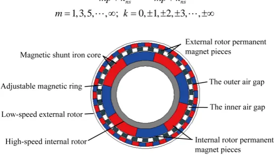
The magnetic field modulation technique is based on the basic structure of the internal mesh permanent mag-netic gear, which can modulate the permanent magmag-netic field to achieve the goal of non-contact transmission [12]. Its structure is shown inFigure 1. The structure of magnetic field modulation permanent magnet gear is studied in this paper.
In the structure, the internal mesh gear mainly includes:
1) A high-speed internal rotor which consists of internal rotor permanent magnet and the inner yoke. 2) A low-speed external rotor which consists of external rotor permanent magnet and the outer yoke.
3) The adjustable magnetic interleaved ring which consists of high permeability material and non-magnetic materials. Its function is modulation magnetic field of the inside and outside rotor.
4) The inner and outer layers are a air gap between the adjacent rotors. Its assembly structure is shown in
Figure 2.
According to the theory of electromagnetic field, in the modulation permanent magnet transmission after modulated the magnetic field, the inside and outside permanent magnet ring will produce a space magnetic flux density harmonics and the magnetic flux density harmonic number is [13]:
,
1, 3, 5, , ; 0, 1, 2, 3, ,
m k ns
p mp k
m k
= +
= ∞ = ± ± ± ±∞ (3)
where: p is the number of pole pairs of rotor permanent magnet, ns is the number of pole blocks of magnetic ring tone.
The angular velocity of space magnetic flux density harmonics is:
,
1, 3, 5, , ; 0, 1, 2, 3, , ns
m k r s
ns ns
k mp
mp k mp k
m k
ω = ω + ω
+ +
= ∞ = ± ± ± ±∞
[image:2.595.177.449.550.706.2](4)
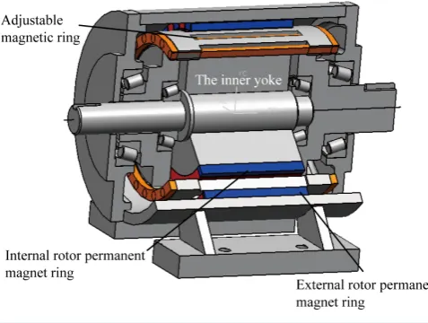
Figure 2. An assembly structure of magnetic field modulation permanent magnet gear.
where: ωr is the speed of inner rotor permanent magnetic loop, ωs is the speed of adjustable magnetic ring. In the structure the modulation magnetic ring is fixed, the internal and external permanent magnet ring rotates so as to achieve torque transmission. Therefore, in the formula (4) ωs=0, the transmission ratio of permanent magnet gear equipment is:
out in r r s n G p n n p ω ω = = − - (5)
where: the negative “−” represents that the rotation direction of internal and external permanent magnet rotors is opposite. nout is the number of pole pairs of external permanent magnet ring, nin is the number of pole pairs of
internal permanent magnet ring. According to the transmission ratio formula (5), we can know that the transmis-sion ratio of equipment only related to the number of pole pairs of inside and outside permanent magnet ring, but not to the number of pole plates of adjustable magnetic ring.
3. The Model of Modulation Permanent Magnetic Transmission
3.1. Material PropertiesPermanent magnet material is NdFeB, which is the linear demagnetization curve (NdFe30). The main parame-ters and constant parameparame-ters are shown inTable 1 [14]. In addition, the yoke part of internal high-speed rotor and external low-speed rotor are structural steel. Its modulus of elasticity is E = 206 Gpa, Poisson ratio is μ = 0.28, density is DENS= 7850kg/m3.
3.2. Permanent Magnet Gear Finite Element Model
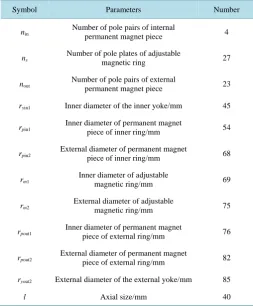
The main structural parameters of finite element model of the gear transmission are selected from the optimized parameter data by research team designing shown asTable 2.
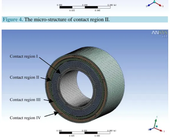
According toTable 2 and the structure parameters of permanent magnet gear and formula (5), we can get the transmission ratio is 5.75. In order to simplify the model without affecting the accuracy of model, we omitted some subordinate structural parameters, such as structure smoothing and rounding. The interference checking on it is completed. Then the model is been imported into ANSYS. The established finite element model is shown in
Figure 3, in which the microstructure of the adjustable magnetic ring can be seen inFigure 4 (the microstruc-ture of contact region II).
3.3. Set the Contact Options
[image:3.595.190.429.86.266.2]Permanent magnet remanence/T 1.10
Permanent magnet coercive force/KA/m −838.00
Permeability of vacuum 4π × 10−7
Relative permeability 1.0997
Magnetization/A/m −8.9 × 10⁵
Permanent magnet conductivity/S/m 625,000
Table 2. The structure parameters of modulated permanent magnet gear.
Symbol Parameters Number
nin
Number of pole pairs of internal
permanent magnet piece 4
ns
Number of pole plates of adjustable
magnetic ring 27
nout Number of pole pairs of external permanent magnet piece 23
ryin1 Inner diameter of the inner yoke/mm 45
rpin1 Inner diameter of permanent magnet
piece of inner ring/mm 54
rpin2
External diameter of permanent magnet
piece of inner ring/mm 68
rm1
Inner diameter of adjustable
magnetic ring/mm 69
rm2 External diameter of adjustable magnetic ring/mm 75
rpout1 Inner diameter of permanent magnet
piece of external ring/mm 76
rpout2
External diameter of permanent magnet
piece of external ring/mm 82
ryout2 External diameter of the external yoke/mm 85
[image:4.595.190.442.228.372.2] [image:4.595.185.439.411.718.2]Figure 3. The finite element model of modulated permanent magnet gear.
Figure 4. The micro-structure of contact region II.
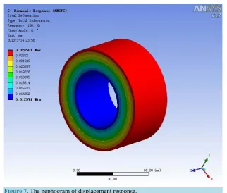
[image:5.595.169.458.466.701.2]modality is the fundamental frequency modality of the structure, which has a great effect on the actual vibration of the structure. After analyzing and comparing of the initial six order modal displacement response amplitude, we can get that the maximum of the displacement response amplitude is the maximum displacement of the first-order modality (0.024501 mm), and the maximum displacement response amplitude is smaller than the fit clearance of inner and external ring of the permanent magnet gear transmission. Therefore when it operates the vibration of rotors is lowest and almost without noise. The structure fits the design requirements and technology demands of permanent magnet gear transmission. It can ensure the system running smoothly under the sinusoi-dal excitation and vibrating lower.
5. Conclusion
The harmonic response analysis can be used to determine the steady state response of a linear structure which is
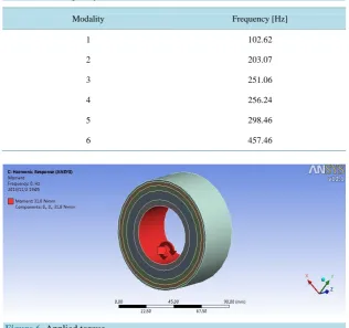
Table 3. The frequency of the initial six modalities.
Modality Frequency [Hz]
1 102.62
2 203.07
3 251.06
4 256.24
5 298.46
[image:6.595.155.472.419.716.2]6 457.46
Figure 7. The nephogram of displacement response.
under a changed load by the harmonic rules. In this paper, the harmonic response of a modulation NdFeB per-manent magnetic transmission equipment is analyzed and its response change regularity. The maximum dis-placement response amplitude of the first-order modality is maximum in the entire frequency. It is 0.024501 mm and the maximum displacement response amplitude is smaller than the fit clearance of inner and external ring of the permanent magnet gear transmission. In design, according to the response change regularity, designer can better analyze the stress which corresponds to the peak frequency and predicts the operating stability and con-tinuous dynamic of the system. Thus, we can judge the system whether it will be non-effectiveness which is caused by resonance, fatigue or other forced vibration in operation. So in practical design or application, we need to try to control the first-order modal displacement response amplitude as much as possible so that the equipment and operation system can be ensured to have better reliability and stability.
Acknowledgements
This project is supported by National Natural Science Foundation of China (No. 51305472), Natural Science Foundation of Chongqing CSTC, China (CSTC2013yykfB0184) and the Postgraduate Education Innovation Foundation of Chongqing Jiaotong University under Grant 20120108.
References
[1] Wang, H.-S., Hou, Y.-P. and Cheng, S.-K. (2008) Development and Prospect of Non-Contact Permanent Magnetic
Gear Transmission. MEMS, 02, 71-73.
[2] Zhang, J.-T. and Xia, D. (2005) Research on the Transmission Characteristic of a Magnetic Gear. Machinery Design &
Manufacture, 05, 69-70.
[3] Yang, C.J. and Gu, H.W. (2008) Current Situation of the Permanent Magnetic Drive Technology and Its Prospect.
Journal of Mechanical Transmission, 32, 1-5.
[4] Liu, X.H. (2008) Design and Research on a Novel Field Modulated Magnetic Gear. Shanghai University, Shanghai.
[5] Nagrial, M.H., Rizk, J. and Hellany, A. (2007) Design and Development of Magnetic Torque Couplers and Magnetic
Gears. International Conference on Electrical Engineering, 11-12 April 2007, 1-5.
[6] Wang, J.L. and Liu, Q.F. (2010) The Principle and Application of Magnetic Gear Transmission. Journal of Mechanical
[14] Ge, Y.J., Xin, Q. and Nie, C.Y. (2012) Research on the Relationship of the Field Modulated Permanent Magnetic Gear