http://dx.doi.org/10.4236/jmp.2015.62019
Investigation of Scattered Radiation Dose at
the Door of a Radiotherapy Vault When the
Maze Intersects the Primary Beam
Sean Michael Tanny, Nicholas Niven Sperling, E. Ishmael Parsai
Department of Radiation Oncology, Division of Medical Physics, University of Toledo Medical Center, Toledo, Ohio, USA
Email: [email protected]
Received 27 January 2015; accepted 13 February 2015; published 25 February 2015
Copyright © 2015 by authors and Scientific Research Publishing Inc.
This work is licensed under the Creative Commons Attribution International License (CC BY).
http://creativecommons.org/licenses/by/4.0/
Abstract
NCRP 151 provides very detailed examples demonstrating the necessary concerns for shielding a conventional radiotherapy vault with a maze where the useful beam is parallel to the maze. How-ever, it provides little guidance on how to properly shield a vault with the maze-wall acting as part of a compound primary barrier. We have modeled a new radiotherapy vault with this configura-tion and assessed the addiconfigura-tional photon shielding burden at the door with MCNP5. MCNP simula-tions demonstrated an increase in overall photon shielding burden at the door relative to calcula-tions that only consider photon workloads presented in NCRP 151. Two additional components of scattered radiation are considered and methods for calculation are presented.
Keywords
Radiation Protection, Radiation Shielding, Scatter, Monte Carlo
1. Introduction
NCRP Report 151 lays out the broad considerations for shielding a megavoltage linear accelerator to achieve reasonably low levels of radiation [1]. An example is provided for the medical physicist to accurately calculate the shielding requirements for a radiation therapy vault with a maze. However, the example for a conventional linear accelerator vault presented in NCRP 151 only applies to a layout where the useful beam does not intersect the maze barrier. Facilities utilizing a design where the primary beam does intersect the maze barrier require ad-ditional guidance.
or a configuration with the useful beam intercepting a standard maze. A direct shielded door or shortened maze design for a high-energy accelerator (>10 MV) requires considerable shielding material to provide adequate tenuation from direct photo-neutrons and gamma capture photons. Designing a longer maze barrier helps to at-tenuate these effects, but requires more shielding material. Allowing adjacent vaults to share barriers minimizes the amount of shielding material for a facility, which can lead to having the primary beam incident on the maze depending on the facility geometry. With a beam incident on the maze, it is desirable to split the primary barrier shielding between the maze barrier and the maze wall, making the maze barrier as thin as possible to minimize dose at the door and the necessary volume of concrete required for the facility. Splitting the primary barrier into a compound barrier introduces new considerations, namely primary beam that is scattered from the maze barrier to the door, primary transmission through the maze barrier incident on the door, and primary transmission through the maze barrier that is then scattered to the door by the far maze wall.
A variant of this problem was previously investigated by Facure et al. where they studied the effects of pho-ton dose-equivalent at the vault door from “unusual” gantry orientations [2]. They found that an increase by up to a factor of 7 for photon dose-equivalent could be achieved by orienting the gantry at 45˚ to the maze normal, but that photon dose-equivalent was reduced by approximately a factor of 2 by pointing the gantry directly to-wards the maze. However, their study did not attempt to define a method to calculate this photon dose. Addi-tionally, they did not simulate higher energy accelerators capable of producing beams > 10 MV.
Biggs explored the necessary thickness of door shielding for 4 and 10 MV accelerators when the primary beam intercepted a standard maze and a shortened maze [3]. They concluded that the relative accuracy of the NCRP 49 and NCRP 51 formalisms provided a conservatively safe estimate of the photon dose-equivalent, but that the dose-equivalent at the door was higher for situations where the beam was perpendicular to the maze. This increase in dose-equivalent was larger for the higher-energy beam. There was also a greater variation in dose-equivalent at different positions across the door than with a conventional vault.
Zavgorodni evaluated scattered dose transmitted through under-shielded ceilings incident on adjacent build-ings in 2001, similar to the situation of the maze barrier [4]. This investigation included both simulation and di-rect measurement, demonstrating agreement within 40%. They determined that a power-law fit for scatter frac-tions was adequate to model the measured dose for all energies. Their work did include a method for calculating the scattered dose from a broad beam, but the scatter fractions were calculated over large distances (5 - 10 me-ters) whereas the door is commonly situated within half that distance. With the area of interest much closer to the scattering source, we no longer can approximate the source as a point. Effects from an elongated scattering source will be more pronounced at the shorter distances involved when shielding the door.
Our goal is to identify how the beam intercepting the maze barrier contributes to the photon shielding work-load at the door. We have developed a model consistent with the derivation presented by Zavgorodni and have created a Monte Carlo simulation to determine the appropriate shielding in this situation [4]. The additional photon workload has been compared to the photon dose calculated using the existing formalisms presented in NCRP 151 for leakage scatter, patient scatter, leakage transmission, and wall scatter [1].
2. Methods
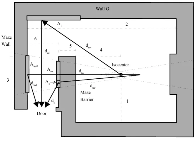
2.1. Vault LayoutFigure 1 presents the layout of the vault, with the relevant dimensions listed inTable 1. The primary beam is normally incident on the maze barrier, but is not directly incident on the vault door. The bold arrows onFigure 1 depict the paths of scattered radiation to the door. The path for leakage transmission from isocenter through the maze barrier to the door centerline has been omitted for clarity, but should still remain a consideration for shielding in this configuration.
2.2. Monte Carlo Model
A Monte Carlo model of the vault was designed using the MCNP5 code from Los Alamos National Laboratory
Figure 1.Diagram of simulated vault. Numbered segments correspond to lengths inTable 1. Thick arrows show potential paths for radiation to reach the door. The path for leakage transmission from isocenter to door centerline has been omitted for clarity.
Table 1. Vault dimensions for MCNP simulation and shielding design calculations.
Dimension Number on Figure 1 Distance (m)
Isocenter to Wall G 1 4.42
Outer Boundary of Door to Far Edge of Maze 2 3.97
Outer Boundary of Door to Mid-line of Field 3 2.60
Isocenter to Maze Barrier 4 3.28
Maze Barrier Thickness 5 1.22
Maze Width 6 1.98
Wisconsin 53711-4948). Spectra for 6 and 18 MV were run. These were compared with the accepted spectra from Mohan et al. and determined to be comparable [6]. A planar source was created at the opening of the ma-chine head directly below the multi-leaf collimator (MLC) with an opening angle corresponding to a 40 × 40 cm2 field at isocenter. A 40 × 40 × 40 cm3 water phantom was centered about isocenter (i.e. the center of the phantom was placed at isocenter). Simulations were run for 1010 histories. Photon energy cutoffs were set to 30 keV to decrease simulation time. Preliminary runs showed less than a 2% difference for simulations with a 10 keV photon cutoff.
The maze barrier was divided lengthwise into 11 cm thick cells, with the 11 cm furthest from isocenter being divided into 10 cm long by 20 cm high segments. The relative photon-importance within each layer of the maze barrier was increased from 1 - 10. The photon importance for cells beyond the maze barrier was maintained at 10. The tally region beyond the door was subdivided into 20 × 10 × 2 cm3 cells that were vertically centered along the beam line. Tallies were placed beyond each barrier and beyond the door, as well as a 20 × 20 × 1 cm3 scoring plane centered about isocenter at 20 cm depth within the water phantom. Dose at isocenter was then scaled appropriately using the TMR (20) to determine dose at dmax.
[image:3.595.89.538.381.494.2]at-tenuation. The second half of the maze barrier was used to avoid any variation between initial and equilibrium HVLs. The simulated HVL was compared to a calculated HVL using TVLs for concrete presented by NCRP 151 [1].
Scatter-fractions were derived from the relative contributions of cells in the outer portion of the maze barrier to the relative contribution of dose in the door. These were normalized to the strength at 1 m from the maze bar-rier via by correcting for inverse square effects. Scatter intensity was renormalized by dividing the ratio of the simulated field size to a 400 cm2 field. This process is summarized in Equation (1),
( )
Cell 2 2Maze 400 cm 1 m k k k j k D d a D F
θ =
(1)
Simulated concrete material was a density of 2.35 g⋅cm−3 and a composition by weight of 2.2% hydrogen, 57.5% oxygen, 1.5% sodium, 0.12% magnesium, 2.0% aluminum, 30.5% silicon, 1.0% potassium, 4.3% cal-cium, and 0.6% iron [7]. This composition is somewhat different from the simulated materials used by Biggs, and Facure et al. Biggs cites their concrete composition as being from NCRP Report 31 and Facure et al. util-ized compositions used during prior work [2] [3]. The compositions differ in the relative composition by weight, along with minor additives, such as sodium, magnesium, and potassium, but all works utilize a density of 2.35 g⋅cm−3.
2.3. NCRP Formalism for Door Workload
The method for calculating the patient-scatter workload, HPS, at the vault door is presented in Equation (2),
( )
(
)
Maze 1 1
2 400
j j
PS
j sca sec zz
W U a A F
H
d d d
θ α
=
∑
(2)where aj(θ)is the scatter fraction of patient-scattered radiation at angle θ and energy j, Wj is the primary
work-load for energy j, UMaze is the use factor for the maze, F is the maximum field size in cm2 at isocenter, A1 is the
area of wall G visible from the maze entrance, α1 is the concrete albedo for wall G, dsca is the distance from
tar-get to patient (typically 1 m), dsec is the distance from patient to wall G, and dzz is the distance from wall G to the
maze entrance [1].
Leakage transmission and leakage scatter, HLT and HLS, are calculated using Equations (4) and (5) respectively.
1 2 TVL 1 TVL 10 t j M − − +
= (3)
( )
Maze 2 j j LT j LW LU M
H
d
=
∑
(4)(
)
Maze 1 1 2 j
LS
j sec zz
W LU A
H
d d α
=
∑
(5)L is the maximum allowable amount of head leakage, taken as 0.001, Mj is the full maze barrier attenuation
factor given by Equation (3), dLis the distance from the isocenter to the center of the door, t is the thickness of
the maze barrier including slant thickness, and the other variables are equivalent to what was defined above for patient scattered radiation [1].
The primary wall-scattered radiation component discussed in NCRP 151 and McGinley 2002 is not present in the current configuration, and is not calculated here [1] [8].
2.4. Additional Photon Components for Compound Barrier Configuration
mean free path (MFP) from the left edge of the maze barrier in Figure 1. We can determine the MFP from the half-value layer (HVL) by Equation (6),
( )
HVL MFPln 2
= (6)
We assume that radiation which makes it to this point in the maze barrier escapes without further attenuation. Radiation reaching within one MFP of the left edge of the maze barrier has a high likelihood of scattering and then escaping the barrier. Typically there is one predominant angle for calculating the scatter workload, but our situation applies to an extended source at close range, thus increasing the range of relevant scattering angles considerably. A more accurate method to calculate the scattered dose is to divide the irradiated area into sub- segments and calculate the contribution from each one. We utilize the scatter fractions respective to the angle from each subsection of the maze barrier to the door, scaled by the area of the maze barrier subsection over the total irradiated area of the maze. The effective source strength is given by the workload of each energy at iso-center multiplied by the maze attenuation factor, given by Equation (7). This is summed over the total area of the maze exposed to primary radiation. The maze-scatter workload for the door, HMS, can be calculated as shown
in Equation (8),
1 2 TVL MFP 1 TVL 10 t j B − − − +
= (7)
( )
(
)
Maze 2
400
j j j k k
MS
jk tar k tot
W B a U A F
H
d d A
θ
=
∑
(8)where aj(θk)is the scatter fraction for the k-th maze section of the j-th energy, t is the thickness of the maze
bar-rier, Ak is the area of the k-th maze section, Atot is the total area of the far maze barrier irradiated, dtar is the
dis-tance from the target to the far side of the maze, and dk is the distance from the k-th maze section to the point in
the door.
Primary transmission scattered from the maze wall is calculated using Equation (9),
(
)
Maze Wall Wall 2 j j
WS
j WD TW
W M U A
H
d d α
=
∑
(9)where Wj and UMaze are as defined above, Mj is given by Equation (3), AWall is the irradiated area of the maze
wall, αWall is the concrete albedo of the maze wall, dTW is the distance from the target to the maze wall, and dWD
is the distance from the maze wall to the door.
2.5. Total Photon Workload at the Door
The scattered photon shielding workload at the door for the gantry directed at the maze, HMaze, can be calculated
as the summation of these different components, as shown in Equation (10),
Maze PS LS LT MS WS
H =H +H +H +H +H (10)
Unlike standard vault design where there is a greater symmetry between radiation dose at the door for a single gantry angle and overall radiation dose at the door, this current vault design is very sensitive to the direction of the radiation beam. Rather than multiplying HMazeby a single factor to get HDoor, only the patient scatter, leakage
scatter, and leakage transmission components can be extended to other gantry angles with the standard multi-plier of 2.64 [1] [8]. We do not explore the accuracy of this empirical factor in this study. The contribution of maze-scatter and wall-scatter should be negligible when the gantry is not directed towards the maze. Thus, the total photon workload at the door, HDoor, can be calculated by Equation (11),
(
)
Door 2.64 PS LS LT MS WS
H = × H +H +H +H +H (11)
[image:5.595.243.381.280.339.2]3. Results
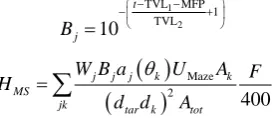
3.1. Monte CarloFigure 2. Simulated vs. calculated HVLs within the maze barrier. Normalized to intensity halfway through the maze barrier.
13.1 cm compared to 10.0 cm and 13.1 cm for concrete HVLs calculated from NCRP 151 for 6 and 18 MV, re-spectively [1]. These are demonstrated inFigure 2. The mean difference between simulated attenuation and the fit value was 0.97% and 0.23% for 6 and 18 MV, while the statistical uncertainty of each tally within the maze barrier was less than 0.05%. Of the additional photon dose in the door, 90.8% ± 2.8% was contributed by the fi-nal 11 cm of the maze barrier for both 6 and 18 MV.
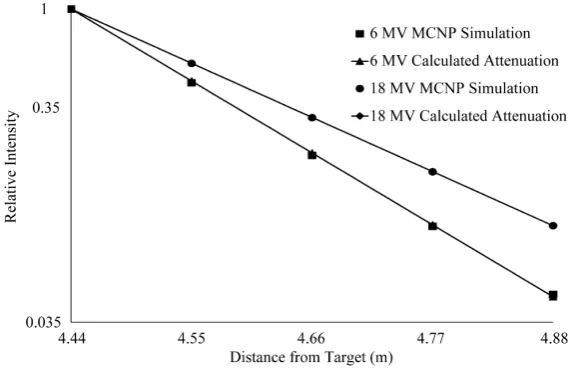
The maximum dose in the door from maze-scattered radiation relative to the dose at isocenter was 6.81 × 10⁻⁹ ± 17.6% for 6 MV. The maximum dose in the door per Gray at isocenter was 5.20 × 10⁻⁷ ± 0.3% and 5.84 × 10⁻⁷ ± 0.2% for 6 and 18 MV, respectively. The location of maximum dose in the door was at the corner furthest from the maze barrier. The tallies nearest the maze barrier recorded 80% ± 0.4% of the maximum dose within the door for 6 MV. Scatter fractions from concrete are presented inFigure 3 andFigure 4 and numerically in
Table 2. These are calculated from two of the tallies within the door. The range of angles covered extends from 16 to 78 degrees, with most of these being covered by both tallies.
3.2. NCRP Calculation Formalism
Table 3presents results from an NCRP style calculation for the relative contributions of photon dose at the door in Gray per Gray delivered to isocenter. Patient scattering and wall scatter albedos were taken as 0.5 MeV effec-tive energy. Use of this energy for patient scatter is recommended by NCRP 151 [1]. Wall scatter within the maze is dealing with a significantly lower effective energy once the primary beam has been transmitted through the barrier. Gamma-capture photons were not simulated, but were calculated for 18 MV. These dominate the to-tal photon shielding burden for high-energy, reaffirming that scattered radiation doses can be safely neglected when shielding gamma-capture photons.Table 4presents equivalent dose rates at the door for a machine with a weekly workload of 1000 Gray.
4. Discussion
The scattering fractions derived from the MCNP simulation require some attention. There is similar data for scattering phenomenon from the patient, but patient scatter fractions are not expected to be ideal for this situa-tion. There are several differences between the situation of patient scatter and the situation presented here. The Zeff of concrete can vary between 12 - 13, while the Zeffof tissue is ~8. The spectral changes introduced by the
Figure 3. Simulated 6 MV maze scatter fractions.
[image:7.595.88.536.515.611.2]Figure 4. Simulated 18 MV maze scatter fractions.
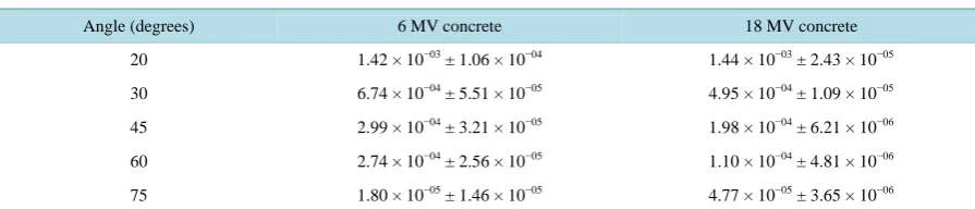
Table 2. Simulated maze scatter fractions for 6 and 18 MV.
Angle (degrees) 6 MV concrete 18 MV concrete
20 1.42 × 10−03 ± 1.06 × 10−04 1.44 × 10−03 ± 2.43 × 10−05
30 6.74 × 10−04 ± 5.51 × 10−05 4.95 × 10−04 ± 1.09 × 10−05
45 2.99 × 10−04 ± 3.21 × 10−05 1.98 × 10−04 ± 6.21 × 10−06
60 2.74 × 10−04 ± 2.56 × 10−05 1.10 × 10−04 ± 4.81 × 10−06
75 1.80 × 10−05 ± 1.46 × 10−05 4.77 × 10−05 ± 3.65 × 10−06
Both of these data sets demonstrate larger scattering fractions than our simulations, but we still find that the contribution is not negligible.
Table 3. Relative intensities of sources of photon dose equivalent at the vault door as per an NCRP style calculation. Values are in Gy at the door per Gy at isocenter. Contributions are calculated for the radiation field pointing towards the maze.
Photon component 6 MV 18 MV
Patient scatter 1.68 × 10⁻⁸ 1.17 × 10⁻⁸
Leakage scatter 1.21 × 10⁻⁸ 1.21 × 10⁻⁸
Leakage transmission 2.23 × 10⁻¹⁰ 8.31 × 10⁻¹⁰
Maze scatter 3.99 × 10⁻¹⁰ 1.95 × 10⁻¹⁰
Wall scatter 2.27 × 10⁻⁸ 1.25 × 10⁻⁷
Gamma capture --- 6.49 × 10⁻⁷
Total (Excluding gamma capture) 5.23 × 10⁻⁸ 1.49 × 10⁻⁷
Table 4. Dose equivalents in Sv∙wk−1 at the vault door for a machine with a weekly workload of 1000 Gy.
6 MV calculated 6 MV simulated 18 MV calculated 18 MV simulated
HMaze 5.23 × 10⁻⁵ 1.30 × 10⁻⁴ 1.57 × 10⁻⁴ 1.46 × 10⁻⁴
HDoor 1.01 × 10⁻⁴ -- 8.41 × 10⁻⁴ --
TVL for gamma-capture photons will be enough to effectively shield this lower energy scatter. Additionally, for 18 MV, the gamma capture photon dose equivalent is nearly 5 times greater than the scattered photon dose. Thus, for higher energy machines this additional photon dose equivalent can safely be ignored when shielding for gamma capture photons.
The NCRP formalism calculates that the additional shielding workload at the door accounts for 20% of the photon dose equivalent at 6 MV for a single gantry angle and is approximately 9% of the overall photon dose for all gantry angles. MCNP simulation results demonstrate a significantly smaller effect. The components of wall scatter and maze scatter only contribute to 3% of the total photon dose at the door, while all components besides gamma capture contribute 7%. This supports that scatter doses to the door can still be disregarded for high- en-ergy accelerators in this configuration. While the relative contribution of photon dose-equivalent for 18 MV is lower, the absolute contribution is still larger than the contribution from 6 MV. This supports the previous find-ings of Biggs [10]. Similar to what Biggs found, we also determine that the dose distribution at the door is no longer uniform in this configuration, but varies across the door by 20% for 6 MV. The location of dose maxi-mum is at the corner of the door furthest from the maze barrier, which should be expected as it will have the shallowest scattering angles from maze scatter.
5. Conclusion
We have developed a method to account for additional photon dose-equivalent at the maze door for a high-ener- gy therapy accelerator that has been verified by MCNP simulation. This equation utilizes scatter fractions and TVLs of concrete available to the medical physicist from NCRP 151. The agreement between analytic calcula-tions and simulated results demonstrated that the additional dose-equivalent at the vault door was increased from a traditional vault layout, discounting capture gamma photons. However, further study needs to be done to ac-curately determine the proper scatter fractions for this type of situation. Until such time, our methodology should only be used as an approximation of the additional shielding burden for the door.
References
[1] National Council on Radiation Protection and Measurements (2005) Structural Shielding Design and Evaluation for Megavoltage X- and Gamma-Ray Radiotherapy Facilities.
[2] Facure, A., Cardoso, S.C., da Rosa, L.A.R. and da Silva, A.X. (2010) Radiation Protection Dosimetry, 138, 251-256. http://dx.doi.org/10.1093/rpd/ncp245
[3] Biggs, P. (1991) Health Physics, 62, 465-472. http://dx.doi.org/10.1097/00004032-199110000-00001
[5] X-5 Monte Carlo Team (2005) LA-UR-03-1987. Los Alamos National Laboratory, USA.
[6] Mohan, R., Chui, C. and Lidosfsky, L. (1985) Medical Physics, 12, 592-597. http://dx.doi.org/10.1118/1.595680 [7] Williams III, R.G., Gesh, C.J. and Pagh, R.T. (2006) Pacific Northwest National Laboratory, 14-18.
[8] McGinley, P. (2002) Shielding Techniques for Radiation Oncology Facilities. 2nd Edition, Medical Physics Publishing, Madison.
[9] Taylor, P.L., Rodgers, J.E. and Shobe, J. (1999) Medical Physics, 26, 1442-1446. http://dx.doi.org/10.1118/1.598670