© 2017, IRJET | Impact Factor value: 5.181 | ISO 9001:2008 Certified Journal | Page 2294
PERFORMANCE ANALYSIS OF DIFFERENT MODULATION SCHEMES
USING Wi-MAX AND LTE
Miss Prachi N Zodpe, Dr Prof S P Mohani
1
Electronics and Telecommunication (digital system), Government college of engineering, Jalgaon,
Maharashtra, India
2
Prof
.
Electronics and Telecommunication (digital system), Government college of engineering, Jalgaon,
Maharashtra, India
---***---Abstract - Wi-MAX and LTE both in light of IEEE standard,
are two opponent innovations by the by, are in fact fundamentally the same as. Transfer innovations have been contemplated and considered in the institutionalization procedure of the up and coming era of MIMO framework, for example, LTE 8, Advance LTE 10, IEEE 802.16e, IEEE 802.16m.
This work presents and looks at components of two advances in physical layer, and furthermore gives execution investigation of various regulation plans (BPSK, QPSK, and 16-QAM) in Wi-MAX and LTE advances. Overall Interoperability for Microwave get to (Wi-MAX) and Long Term Evolution (LTE) are relied upon to be basic advances for portable broadband remote correspondence in the up and coming years. The device utilized for execution investigation of Wi-MAX and LTE is MATLAB 16.The IEEE 802.16 gives better versatile voice, video and information.
The work breaks down and analyzes two propelled advances Wi-MAX and LTE in physical layer and furthermore gives execution investigation of various balance plans, for example, BPSK , QPSK, 16-QAM, and 64-QAM in light of SNR or Eb/No and BER. A standout amongst the most critical multi-bearer transmission systems utilized as a part of the most recent remote correspondence field is known as Orthogonal Frequency Division Multiplexing (OFDM).
1. INTRODUCTION
The quick growth in multimedia controlled applications has triggered an insatiable thirst for high data rates and resulted in an increased demand for technologies that support very high speed transmission rates, mobility and efficiently utilize the available spectrum & network resources. OFDM is one of the paramount resolutions to achieve this goal and it offers a promising choice for future high speed data rate systems.
A number of attractive approaches have been proposed & implemented to reduce PAPR with the expense
A number of attractive approaches have been proposed & implemented to reduce PAPR with the expense of increase
transmit signal power, bit error rate (BER), computational complexity and data rate loss etc. So, a system trade-off is required. These reduction techniques are basically divided into three types of classes such as signal distortion, multiple signaling & probabilistic and coding In this paper, sufficiency cutting and sifting based plan (flag twisting) is utilized to lessen PAPR with a little trade off of BER. The primary goal of this paper is to research the similar execution examination of various higher request regulation procedure on that specific outline.. IEEE 802.16e is a mobile version of Worldwide Interoperability for Microwave Access (Wi-MAX) that plays an important role in the evolution towards 4G. The use of specialized mathematical tools such as MATLAB/Simulink or Mathematics is widely extended to perform such simulations. These tools provide a wide set of built-in libraries that allow a rapid development of prototypes.
We also observe that the downlink of mobile Wi-MAX network can support video streaming up to 4 Mbps with the Mean Opinion Score (MOS) value of 4.5. On the uplink, the bitrate of 1Mbps is supported with MOS 4.5 at the cell center and with MOS 3.2 at the cell edge, respectively. On the uplink, the bitrate of 1 Mbps is supported with MOS 4.5 at the cell center and with MOS 3.2 at the cell edge, respectively.
We find that the VoIP quality at the cell center is perfect, where the value of Perceptual Evaluation of Speech Quality exceeds 4. At the cell edge, the quality is degraded but still adequate. We also observe that the downlink of mobile Wi-MAX network can support video streaming up to 4 Mbps with the Mean Opinion Score (MOS) value of 4.5. On the uplink, the bitrate of 1Mbps is supported with MOS 4.5 at the cell center and with MOS 3.2 at the cell edge, respectively. On the uplink, the bitrate of 1 Mbps is supported with MOS 4.5 at the cell center and with MOS 3.2 at the cell edge, respectively.
© 2017, IRJET | Impact Factor value: 5.181 | ISO 9001:2008 Certified Journal | Page 2295
provided. Finally, the handover case has very limited impact to the overall quality degradation of both VoIP and video streaming.
Wi-MAX and LTE are playing an important role in the evolution towards 4G. As a mobile version of Wi-MAX, mobile Wi-MAX uses similar technologies and has comparable performance to LTE . The increased utilization of data websites such as Facebook and You tube ignite the need for higher capacity and higher data rate supported technology. The increased utilization of data websites such as Facebook and You tube ignite the need for higher capacity and higher data rate supported technology. The development of the 4G (4th generation) Orthogonal Frequency division multiple access (OFDMA) based wireless technologies such as Mobile Wi-MAX (Worldwide Interoperability for Microwave Access) and 3GPP (3rd Generation Partnership Project) LTE (Long Term Evolution) which have been identified as promising, permitting higher data rate in wireless broadband access. The specification of the bandwidth, modulation and coding scheme, data rate, multiplexing, error correction, transmitting data in frames, synchronization between transmitter and receiver.
International standards do not define boundaries for subscriber module usage. Additionally, dead spot and areas of poor reception caused due to fading and blocking within coverage further reduce the efficiency of this standard. The concept of Wi-MAX is based on the Open Systems Interconnections (OSI) reference model which has the lowest layer as the physical layer which is based on OFDM technology. The most innovative security features that are presently used wireless access schemes are integrated in Mobile Wi-MAX for voice, data and multimedia services. Such features comprise, Advance Encryption Standard (AES) based authentication and encryption, Cipher-based Message Authentication Code (CMAC) and Hashed Message Authentication Code (HMAC) based control message protection schemes and Extensible Authentication Protocol (EAP) based authentication. Wi-MAX defines a WMAN, a kind of a huge hotspot that provides interoperable broadband wireless connectivity to fixed, portable, and nomadic users. It allows communications which have no direct visibility, coming up as an alternative connection for cable, DSL, and T1/E1 systems, as well as a possible transport network for Wi-Fi hot-spots.
The blend of Multiple-Input Multiple-Output (MIMO) innovation with Orthogonal Frequency Division Multiplexing (OFDM) is considered as the best answer for give high information rates under recurrence specific blurring channels. Far in a strikingly brief time has been accomplished ever. Evolution of wireless access technologies is about to reach its fourth generation (4G).The (LTE) technology for different MIMO-OFDM techniques under realistic assumptions such as user mobility or bandwidth-limited feedback channel. In this paper we present a MIMO
OFDM-based simulator that includes the main physical and link layer functionalities.
A long way in a remarkably short time has been achieved in the history of wireless. Mobile communications systems revolutionized the way people communicate, joining together communications and mobility.
The use of specialized mathematical tools such as MATLAB/Simulink or Mathematics is widely extended to perform such simulations. These tools provide a wide set of built-in libraries that allow a rapid development of prototypes. The use of Multiple –Output (MIMO) technology in combination with OFDM increases the diversity gain and/or the system capacity by exploiting spatial domain. An open-source MATLAB based LTE physical layer test system is displayed in by and by, it is demonstrated that broadly useful reproduction stages like MATLAB prompt long execution times. The current interest for higher information rate administrations from remote system clients is overpowering. The two advances, Wi-Max and LTE, rivaled each other beginning their pre-4G renditions and proceeded with their 4G adaptations while having much in like manner.
2. LITERATURE SURVEY
2.1. HISTORY
2.1.1. First Generation (From now on, referenced as 1G)
The first commercially automated cellular network (the 1G generation) was launched in Japan by NTT (Nippon Telegraph and Telephone) in 1979, initially in the metropolitan area of Tokyo. 1G cellular network were invented in the 1980s. The key idea behind 1G was that the geographical area is divided into cells (typically 10-25km), each served by a “base station.” Cells are small so that frequency reuse can be exploited in nearby (but not adjacent) cells. Metropolitan area of Tokyo. The network had been expanded to cover the whole population of Japan and became the first nationwide 1G network.
Technologies under 1G: 1G comprised of the following Mobile technologies: Mobile Telephone Systems (MTS), Advance Mobile Telephone Systems (AMTS).
© 2017, IRJET | Impact Factor value: 5.181 | ISO 9001:2008 Certified Journal | Page 2296
2.2. SECOND GENERATION (From now on, referenced as 2G)
2G cellular telecom networks were commercially launched on the GSM standard in Finland by Radio linja in 1991.It provided the facility of Short Message Service (From now on, referenced as SMS) and used the bandwidth range of 30 - 200 KHz. 2G used digital signals for voice transmission and had a speed up to 64 kbps.
Technologies under 2G: Some key benefits of 2G Network over it spread ecessors was that, Digital Encryption was supported by 2G systems which had higher penetration efficiency thereby being more efficient network spectrum.2G comprised of the following General Packet Radio Service (GPRS), Code Division Multiple Access (CDMA), Global System for Mobile Communication (GSM) and Enhanced Data Rates for GSM Evolution (EDGE). After
2Gwas launched, the previous mobile telephone systems were coined as 1G Systems. Although it has been eons since its inception, 2G networks are still used in many parts of the world.
Issues with 2G:. As conditions declined, advanced signs began to totally come up short, while simple deteriorated continuously, for the most part holding a call longer and permitting no less than a couple of words to get past. The scope of sound that is passed on is decreased. In less populated ranges, the weaker computerized Signal conveyed on higher frequencies may not be Sufficient to achieve a phone tower.
2.3. THIRD GENERATION (From now on, referenced as 3G)
Voice calls are translated through Circuit Switching. Alongside Verbal correspondence it incorporates information administrations, get to TV/video, new administrations like Global Roaming. 3G utilizes Wide Band Voice Channel that is by this the world has been contracted to a little town in light of the fact that a man can contact with other individual situated in any piece of the world and can even send messages as well. Universal Mobile Telecommunications-2000(IMT-2000), also called 3G or third Generation, is an era of benchmarks for cell phones and versatile broadcast communications administrations satisfying the International Telecommunication Union.
Technologies under 3G: Voice calls are translated utilizing circuit exchanging. It likewise gives offices, for example, Global Roaming Clarity in voice calls, Fast Communication, Internet, Mobile T.V, Video Conferencing, Video Calls, Multi Media Messaging Service (MMS), 3D gaming and Multiplayer Gaming.
Issues with 3G: The information utilization of 3G now and again turns out to be so substantial because of the high
transmission rates that it puts a major load on the system; to reduce which, numerous cell administrators executed information use tops which were disadvantageous toclients.
Fig 2.2 Mission Of Project
2.4. FOURTH GENERATION (From now on, referenced as 4G)
In March 2008, the International Telecommunications Union-Radio interchanges part (ITU-R) determined an arrangement of necessities for 4G gauges, named the International Mobile Telecommunications Advanced (IMT-Advanced) particular, setting crest speed prerequisites for 4G benefit at 100 megabits for each second (Mbit/s) for high portability correspondence, (for example, from trains and autos) and 1 gigabit for each second (Gbit/s) for low versatility correspondence, (for example, people on foot and stationary clients). One of the underlying gadgets to get to 4G organize was USB remote modem which was later trailed by mobile phones with Wi-Max and LTE innovation. A 4G system not only provides voice and other 3G services but also provides ultra-broadband network access to mobile devices.
Technologies under 4G: 4G comprised of the following Mobile technologies: Long Term Evolution (LTE) Standard based on the GSM/EDGE and UMTS/HSPA, 3rd Generation Partnership Project (3GPP), Multiple In Multiple Output (MIMO) smart antenna technology, Orthogonal Frequency Digital Multiplexing (OFDM), 802.16e – Worldwide Interoperability for Microwave Access (Wi-MAX), 802.20– Mobile Broadband Wireless Access (MBWA)
Issues with 4G:In ebb and flow investigate, this issue is tended to by full scale differences methods, otherwise called amass helpful transfer, and furthermore by Beam-Division Multiple Access (BDMA). 3G and 4G parts made for one mainland is not generally good with another landmass sue to conveying recurrence groups.
2.5. FIFTH GENERATION (From now on, referenced as 5G)
© 2017, IRJET | Impact Factor value: 5.181 | ISO 9001:2008 Certified Journal | Page 2297
connectivity, are home automation, smart transportation, security, etc.
Need for 5G:
5G offers help for intuitive sight and sound, voice, video, Internet, and other broadband administrations which are more compelling and more alluring and have Bidirectional exact movement insights.
Improved security highlights; better subjective radio/Software Development Radio (SDR). Higher framework level ghostly proficiency.Several Artificial Intelligence supported applications at high Data transfer capacity with numerous sensors empowered cell phones.
3. SYSTEM DEVELOPMENT
3.1SIMULATION AND RESULT
Simulation procedure
3.1.1 Run Transmitter
The first venture in the reenactment is to utilize the transmitter to make a carefully balanced flag from an arrangement of pseudo-arbitrary bits. When we have made this flag, x(n),we need to make some estimation so fit.
3.1.2 Establish SNR
The signal-to-noise-ratio(SNR),Eb/N0,is usually expressed in decibels, but we must convert decibels to an ordinary ratio before we can make further use of the SNR. If We set the SNR to m dB, then Eb/N0=10m/10.
Using Matlab, we find the ratio,„ebn0‟,from the SNR in decibels, snr db‟, as: ebn0=10^(snr db/10). Note that Eb/N0 is a dimensionless quantity.
3.1.3 Determine Eb
Strength per-bits the aggregate vitality of the flag, isolated by the quantity of bits contained in the flag. We can likewise express vitality per-bit as the normal flag control. Increased by the span of one piece. In any case, the articulation for Eb is: Eb= 1 N•f bit N n=1x2(n), Where N is the aggregate number of tests in the flag, and f bit is the bit rate in bits per-second. Utilizing Matlab , we find the vitality per-bit,eb‟,of our transmitted flag, x‟, that Has a bit rate,fb‟,as: eb =sum(x.^2)/(length(x)∗fb). Since our signal, x(n),is in units of volts, the units of Eb are Joules.
3.1.3. CALCULATE N0
With the SNR and vitality per bit now known, we are prepared to calculateN0,the uneven power ghastly thickness of the commotion. We should simply isolate Eb by the SNR,
Providing we have changed over the SNR from decibels to a proportion. Using Matlab, we find the power spectral density of the noise,„n0‟,given energy per bit„eb‟,andSNR„ebn0‟,as: n0 =eb/ebn0. The power spectral density of the noise has units of Watts per Hertz.
[image:4.595.319.549.189.247.2]3.2 Wi-MAX Physical Layer
Fig 3.1: Wi-MAX Physical Layer (Transmitter Side)
3.2.1 Randomizer
Randomization is the main procedure did in the physical layer after the information bundle is gotten from the higher layers. The randomization procedure is utilized to limit the likelihood of transmissions of non-tweaked subcarriers.The process of randomization is performed on each burst of data on the downlink and uplink, and on each allocation of a data block. The stream of packets is randomized using a pseudorandom binary sequence (PRBS) generator. The randomized bits are the modulo-2 summation of the data with the PRBS output.
3.2.2 Channel Encoding
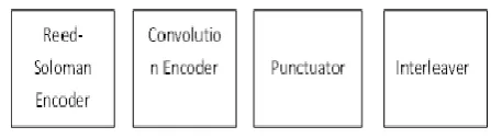
The encoding process consists of a concatenation of an outer Reed-Solomon (RS) code and an inner convolutional code (CC) as a FEC scheme. That means that first data passes in block format through the RS encoder, and then, it goes across the convolutional encoder. The last part of the encoder is a process of interleaving to avoid long error bursts. Now we consider various blocks of channel encoder in detail.
Fig 3.2 Encoding Process in Wi-MAX
3.2.2.1 RS Encoder
A Reed-Solomon code is specified as RS (n, k,t) with l-bit symbols. This means that the encoder takes k data symbols of l bits each and adds 2t parity symbols to construct an n-symbol codeword. Thus, n, k and t can be defined as: n:number of bytes after encoding,
[image:4.595.320.544.548.611.2]© 2017, IRJET | Impact Factor value: 5.181 | ISO 9001:2008 Certified Journal | Page 2298
3.2.2.2 Convolutional encoder
After the RS encoding process, the data bits are further encoded by a binary convolutional encoder, which has a native rate of ½ and a constraint length of 7. A convolutional code is a kind of FEC code that is indicated by CC (m, n, k), in which every m-bit data image to be encoded is changed into a n-bit image, where m/n is the code rate (n> m) and the change is an element of the last k data images, where k is the imperative length of the code.
3.2.2.3 Puncturing process
Puncturing is the process of systematically deleting bits from the output stream of a low-rate encoder in order to reduce the amount of data to be transmitted, thus forming a high-rate code.
3.2.2.4 Interleaver
Interleaving does not change the state of the bits but it works on the position of bits. Interleaving is done by spreading the coded symbols in time before transmission. The incoming data into the inter-leaver is randomized in two permutations. First permutation ensures that adjacent bits are mapped onto non-adjacent subcarriers. The second change maps the neighboring coded bits onto less or more critical bits of heavenly body therefore maintaining a strategic distance from long keeps running of less solid bits. The piece between leaver interleaves all encoded information bits with a square size comparing to the quantity of coded bits per OFDM image.
3.2.3 IQ Mapper
Once the flag has be encoded, it enters the tweak piece. All remote correspondence frameworks utilize a tweak plan to delineate bits to a shape that can be electively transmitted over the correspondence channel.Thus, the bits are mapped to a subcarrier amplitude and phase, which is represented by a complex in-phase and quadrature-phase (IQ) vector. The IQ plot for a modulation scheme shows the transmitted vector for all data word combinations. QPSK, 16QAM and 64QAM modulations are supported by the system.
3.3 OFDM Modulator
In this section firstly inverse fast Fourier transform is used to produce a time domain signal and then cyclic prefix is added to reduce the effect of multipath.
Channel: The channel that we used is pure AWGN. This is a noise channel. This channel effects on the transmitted signals when signals passes through the channel. It adds white Gaussian noise to the input signal. After adding Gaussian noise data is then passed to the receiver.
Receiver: The complementary blocks are implemented in the receiver: the CP is removed, sub carriers are demodulated via the FFT transform, and then sub-carrier de-mapping is performed. After that Channel decoding process is performed with the help of de-interleaver, convolution decoder and RS decoder. Data is then de randomized and in last we get final data.
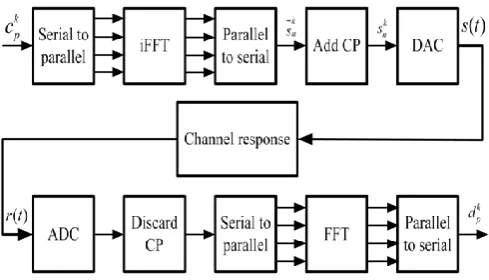
3.3.1 Basic model of OFDM system
[image:5.595.311.556.298.438.2]OFDM is a special form of multicarrier modulation (MCM) with densely spaced subcarriers with overlapping spectra, thus allowing multiple-access. MCM works on the criteria of transmitting data by dividing the stream into several bit streams, each of which has a much lower bit rate and by using these sub-streams to modulate several carriers.
Fig 3.3 Block Diagram of OFDM Transmitter Receiver
In multicarrier transmission, data transfer capacity partitioned in numerous non-covering subcarriers however a bit much that all subcarriers are orthogonal to each other .In OFDM the sub-channels cover each other to a specific degree, which prompts a capable utilization of the aggregate bandwidth[14]. The data grouping is mapped into images, which are conveyed and sent over the N sub-channels, one image for each channel.
The data bit stream of OFDM is divided into N data streams using a rate of with each being parallel to each other. i.e., the available spectrum must be divided into several narrow sub-channels.
4.1 Throughput
Throughput is the rate of effective message delivery over communication channel. The data delivered over a physical, logical link and it can pass through a certain network node. Throughput is normally measured in bits per second and sometimes in data packets per second. The system throughput is the amount of the data rates that are delivered to all terminals in a network.
© 2017, IRJET | Impact Factor value: 5.181 | ISO 9001:2008 Certified Journal | Page 2299
Throughput is basically identical to digital bandwidth consumption, where the load in packets per time unit is indicated as the arrival rate. The throughput in packets per time unit is indicated as the withdrawal rate.
4.2 BER
Bit Error Rate (BER) is an important measurement to determine the integrity of the transmitted data in a communication system.
The performance of the wireless communication system can be determined by analyzing the BER in the noisy channel (transmission medium). Thus combination of different coding and modulation technique will be used to reduce the effect of noise and achieve the optimum BER for high speed data communication.
On the surface, BER is a simple concept its definition is simply:
BER = Errors/Total Number of Bits
Eb/No and BER can also be defined in terms of the probability of error (POE),
POE=1/2(1-erf)√Eb/N0
where ,
erf is the error function.
Eb is the vitality in one piece and No is the commotion control unearthly thickness (commotion control in a 1 Hz data transmission). The vitality per bit, Eb, can be controlled by separating the transporter control by the bit rate. No is in control (joules every second) per Hz (seconds).
4.2.1 BER Measurement
While the basic concept of BER measurement is simple send a data stream through the system and compare the output to the input its execution is not trivial. we don‘t want to wait forever to make a BER measurement, So a pseudorandom data sequence is used for this test We call it "pseudorandom" since we can't make a genuinely irregular flag utilizing deterministic (numerical) techniques. It is likewise conceivable to include Rayleigh (blurring) attributes to the flag, utilizing different channels with variable time postponements to reenact changing way conditions.
The mathematical nature of digital signal transmission also allows computer simulation, but with the practical limits imposed by production variations in system components. In a digital communication, the BER is the received bits with faults at receiver and it is calculated by dividing the faults bits with total number of bits that have been transmitted over a given time period.
The transmitted BER is the ratio of number of sensed bits that are incorrect before error improvement and
the total number of transferred bits. The BER may be better with choosing a strong signal strength by using a slow and robust modulation system, line coding system and by also applying channel coding system such as dismissed forward error correction codes.
4.3 Modulation Technique
4.3.1 Quadrature Amplitude Modulation(QAM)
The QAM is tweak handle in which two sinusoidal bearer are 90 out of stage as for the other transmitted information over a given physical channel. Since the orthogonal bearer possess a similar recurrence band and diverse 90 stage move each can be regulated exclusively transmitted over a similar recurrence band and isolated by demodulation at the beneficiary end. The transporter flag c(t) can be communicated in twice of side band stifled bearer quadrature. C(t) = I(t) cos wct + Q(t) sin wct.
4.3.2 QPSK
It is a multilevel modulation technique it uses 2 bit per symbol to present each phase. By comparing it with BPSK it has more apparitional efficiency. But it required more complex receiver. The QPSK which is the Quadrature Phase Shift Keying is also called 4-PSK (4-Phase Shift Keying). The data which is fed into the modulator is separated in two different channels. Each of these channels is in charge of transporter regulation. The QPSK can show itself in a group of stars chart of four states. Along these lines, it has the ability to encode two bits for every image. Hypothetically, the proficient transfer speed of QPSK is observed to be 2 bit/sec/Hz.
4.3.3 16-QAM
The 16-QAM characterizes the QAM in a 16-state situation. This implies this balance procedure can encode four bits for every image. Much the same as the QPSK, the 16-QAM information is additionally isolated into two unique channels. Thus, two bits are transmitted with each channel.These bits are later combined and added and fed into the channel modulators. Since the 16-QAM signifies 4 bits per symbol. Thus, its symbol rate is ¼. The digital television receives its signal from the source in groups of 16 symbols. The forward error correction bitrates in this case is around 18 Mb/sec. the ratio has been found to be 1/3. The 16-QAM has 16 constellation points in total with each quadrant displaying 4 points.
4.3.4 64-QAM
© 2017, IRJET | Impact Factor value: 5.181 | ISO 9001:2008 Certified Journal | Page 2300
16-QAM is that it can convey higher throughput and in this manner demonstrate better execution.When the data is divided into two different channels, the information sent through the channels is later combined and then they are received by the receiver. The ”Forward Error Correction” for in this state scenario is 2/3. For this reason, its bit rate is 24 megabits per second.
5.1 Simulation Results for BER Performance
The cut and sifted flag is gone through the AWGN channel and BER are measured for various regulation methods. It is appeared from these assumes that the BER execution turns out to be more awful as the CR diminishes.That means, for low value of CR, (More amount of clipping), the BER is more.
[image:7.595.308.571.82.313.2]Model for the Wi-MAX and LTE is built from the standard documents. The performance of the Wi-MAX and LTE –PHY layer was tested and evaluated at different noise levels. We performed our simulation in Matlab Simulink version r2014a.
Fig 5.1 Plot of BER Versus Eb/No Using BPSK
We have preferred the Matlab because it is adequate for the simulation of different signal processing methods used in wireless networks. After running our simulation model at different values of signal to noise ratio we got different values of bit error rate.
Fig 5.2 Plot of Bit Error Rate Using BPSK
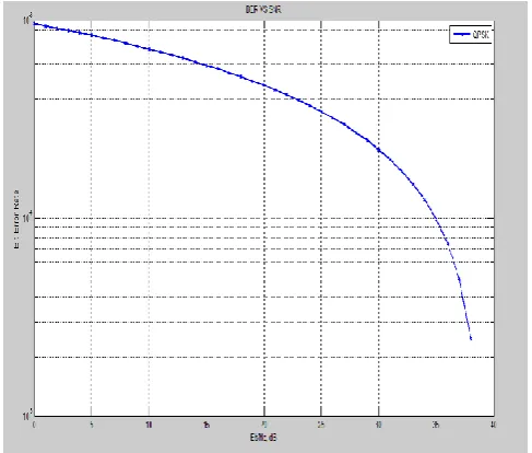
The BER Vs. SNR plots for QPSK, 16-QAM and 64-QAM. From figures it is clear that increasing the value of Signal to Noise Ratio (SNR) decreases the value of Bit Error Rate (BER). If you see the result of Wi-MAX, it is performing well when QPSK is used, almost equal when 16QAM is used and LTE is performing slightly well when 64QAM is used.
Fig 5.3 Plot of BER And SNR Using QPSK
[image:7.595.312.556.434.641.2]© 2017, IRJET | Impact Factor value: 5.181 | ISO 9001:2008 Certified Journal | Page 2301
Fig 5.4 Plot of BER And SNR Using 16 QAM
Fig 5.5 Comparison of Modulation Techniques Used for Wi-MAX and LTE
[image:8.595.42.281.299.454.2]5.2 Simulation Results of SNR Using Image
Fig 5.6 Photograps Showing Effects of Varrying Receiver Signal to Noise Ratio (SNR=40)
Fig 5.7 Photographs Showing Effects of Varying Receiver Signal to Noise Ratio(SNR=35)
[image:8.595.326.541.367.485.2]In this section the result is based on different features Of the image like looks, contrasts, resolution .Receiver SNR should be compared usually with original image of high contrasts and low contrasts. As the input image is given, the output is : As the SNR is larger, the output image is more clear with high resolution .As the SNR is low, the output image is little blur with low resolution.
Fig 5.8 Photograps Showing Effects of Varrying Receiver Signal to Noise Ratio (SNR=10)
5.2 CONCLUSION
Factors that influenced the competition are not only technological. Other factors influenced the fate of the competition. The final outcome is that Wi-MAX people realized that it is necessary to harmonize and integrate with LTE rather than continue rivalling it. This formed the future migration strategy for Wi-MAX.
The clipped & filtered signal is passed through the AWGN channel and BER are measured for different modulation techniques. for low value of CR, (More amount of clipping), the BER is more.
[image:8.595.50.274.531.695.2]© 2017, IRJET | Impact Factor value: 5.181 | ISO 9001:2008 Certified Journal | Page 2302
5.3 Future scope
This section describes the proposed model and algorithm. We Studied basic structure of OFDMA based system in downlink access. Paper focuses on the downlink (DL) transmission from a base station (BS) to mobile unit (MU) and system model used is MIMO downlink state in a time division duplexer (TDD) mode. To study the OFDMA system we selected the region having with latitude 440 3‘ 32.4” north and longitude 1230 5‘ 41.48”west has been choose.
REFERENCES:
[1] R. Pazhyannur, “Comparison of LTE and WiMAX,” in IP NGN Architecture Leadership Journal Q, 2010.
[2] Yang Yang, Honglin Hu, Jing Xu, and Guoquiang Mao, “Relay Technologies for WiMAX and LIE-Advanced Mobile Systems.” IEEE Commun. Mag., vol. 47, no. October, pp. 100– 105, 2009.
[3] D. M. K.N.S. Kumar, M.Kata, P.Chaitanya, “LTE-Advanced :Future of Mobile Broadband,” 2009.
[4] “The Mobile Broadband Standard,” Global Initiative. [Online]. Available: www.3gpp.org. [Accessed: 20-Jan-2015]. [5] “Performance analysis of both WIMAX and LTE Master MDM Internship Performance analysis of both WIMAX and LTE technologies Supervisor : Salima Hamma,” 2013. [6] H. Ekström, A. Furuskär, J. Karlsson, M. Meyer, S. Parkvall, J. Torsner, and M. Wahlqvist, “Technical solutions for the 3G longterm evolution,”IEEE Commun. Mag., vol. 44, no. March, pp. 38–45, 2006.
[7].Agilent, "Digital Modulation in Communications Systems An Introduction",application Note 1298.
[8]. Askar, S.; Al-Raweshidy, H.S., "Performance evaluation of IEEE802.16-2004 WiMAX with fixed high fading channels," Wireless and Microwave Technology Conference (WAMICON), 2011 IEEE 12th Annual , vol., no., pp.1,6, 18-19 April 2011.
[9]. Yong Su Lee; Young-Il Kim; Won Ryu; Lee Ho Jin; TaeSik Kim; Whan-Woo Kim, "BER performance of pilotaided channel estimation in mobile-Wi-MAX in the presence of frame synchronization errors," ICT Convergence (ICTC), 2011 International Conference on , vol., no., pp.485,486, 28-30 Sept. 2011.
[10]. Moraitis, N.; Vouyioukas, D.; Constantinou, Philip, "Propagation Study and Performance Evaluation of a Mobile Wi-MAX System at 3.5 GHz," Communications (ICC), 2011 IEEE International Conference on , vol., no., pp.1,5, 5-9 June 2011.