Development of an expert system for cutting-off process
selection.
CHOW, K. L.
Available from Sheffield Hallam University Research Archive (SHURA) at:
http://shura.shu.ac.uk/19464/
This document is the author deposited version. You are advised to consult the
publisher's version if you wish to cite from it.
Published version
CHOW, K. L. (1995). Development of an expert system for cutting-off process
selection. Masters, Sheffield Hallam University (United Kingdom)..
Copyright and re-use policy
See
http://shura.shu.ac.uk/information.html
101 536 5 57 4
Sheffield Hallam University
REFERENCE ONLY
ProQuest Number: 10694345
All rights reserved
INFORMATION TO ALL USERS
The quality of this reproduction is dependent upon the quality of the copy submitted.
In the unlikely event that the author did not send a com plete manuscript and there are missing pages, these will be noted. Also, if material had to be removed,
a note will indicate the deletion.
uest
ProQuest 10694345
Published by ProQuest LLC(2017). Copyright of the Dissertation is held by the Author.
All rights reserved.
This work is protected against unauthorized copying under Title 17, United States C ode Microform Edition © ProQuest LLC.
ProQuest LLC.
789 East Eisenhower Parkway P.O. Box 1346
Development of an Expert System for
Cutting-off Process Selection
K. L. Chow
A thesis submitted in partial fulfilment of the
requirements of
Sheffield Hallam University
for the Degree of Master of Philosophy
CONTENTS
ITEMS
PAGE
Abstract i
Acknowledgements »
List of figures iii
List of tables iv
Chapter 1
Introduction 1
1.1 Background 1
1.2 Aims and objectives 1
1.3 Cutting-off process 2
1.4 Problems in selecting cutting-off process 4
Chapter 2
Literature Review 7
2.1 Introduction 7
2.2 Cutting-off process selection 7
2.3 Reported uses of expert systems for selection tasks 11 2.4 Reasons for using an expert system in preference to conventional program 14
2.5 Expert system tool selection 17
2.6 Conclusions 19
Chapter 3
Cutting-off process selection: Industrial practice in U.K. 20
3.1 Introduction 20
3.2 Objectives of survey 20
3.3 Survey design 20
3.4 Selection of the survey method 21
3.5 Design of questionnaire 21
3.6 Survey data analysis 24
3.7 Survey results 24
3.7.1 Cutting-off process user company 25
3.7.2 Cutting-off tool manufacturer 33
3.7.3 Cutting-off machine manufacturer 35
Chapter 4
Knowledge engineering for cutting-off process selection
4.1 Review of knowledge engineering \
4.2 Knowledge elicitation
4.3 Results of the knowledge elicitation 4.4 Development of selection methodology
4.4.1 Selection methodology
Chapter 5
Development of cutting-off process selection expert system
5.1 Introduction
5.1.1 Identification of problem 5.1.2 Task analysis
5.1.3 Information processing 5.1.4 Prototype development 5.1.5 System development and test 5.2 The cutting-off process selection system
5.2.1 First level: hardness 5.2.2 Second level: Material 5.2.3 Third level: Tolerance 5.2.4 Fourth level: Surface finish 5.2.5 Fifth level: Kerf loss 5.2.6 Sixth level: Cross section 5.3 Cutting parameter selection system 5.4 Cost analysis system
5.5 Report
Chapter 6 System testing
6.1 Introduction 6.2 Testing procedure 6.3 Phase testing
6.3.1 Phase 1
6.3.1.1 Phase 1 section 1 6.3.1.2 Phase 1 section 2 6.3.2 Phase 2 test
6.3.3 Phase 3 test 6.4 Discussion of results 6.5 Analysis and correlation
6.5.1 Cutting-off process
Chapter 7
Discussions and future work 73
Conclusions 75
Future work 78
References 79
Appendices
Appendix 1 Sawing process
A. 1.1 Power hacksaw A. 1.2 Circular sawing A. 1.3 Friction cutting A. 1.4 Abrasive disc cutting A. 1.5 Band sawing A. 1.6 Oxyfuel gas cutting A. 1.7 Arc cutting A. 1.8 Laser beam cutting A. 1.9 Wateijet cutting
Appendix 2
Expert System Building Tools
A.2.1 ESE - Expert System Environment A.2.2 Knowledge Tool (KT)
A.2.3 Adviser (ICL)
A.2.4 Knowledge Based Management System (KBMS) A.2.5 Application Expert (AE)
A.2.6 Knowledge Engineering System (KES) A.2.7 XI Plus
A.2.8 KAS A.2.9 EXPERT A.2.10 AGE A.2.11 EMYCIN
Appendix 3
Mail Questionnaires 30
A.3.1 Process user 30
A.3.2 Cutting-off machine tool manufacturer 39
Appendix 4
Expert System Verification 43
Appendix 5
Testing Examples 45
A.5.1 Phase 2 test examples 45
A.5.2 Phase 3 tests - Industrial testing 50
Appendix 6
Abstract
The manufacturing engineer is faced with many different processes and a wide variety of alternative combinations of parts and cutting-off tools. The problem is therefore to select the optional and most economical combinations of processes and parameters for cutting-off a given product. To assist in this problem, each cutting-off tool or machine manufacturer and supplier recommends cutting conditions for their products which are neither consistent nor have a scientific base. As with other machining technologies, the cutting-off process domain has an abundance of data, but veiy little documented knowledge.
It was proposed to undertake an investigation into the possibility of using a knowledge-based system for the selection of cutting-off processes, cutting-tools and the associated parameters.
This project uses a survey to investigate the U.K. industry practice in the selecting of cutting-off process and machines used in their business and the nature of their business. The survey method, design and survey questionnaires as well as the findings are also reported.
From the survey finding and interviews with experts, a prototype system structure has been developed. This system is similar to an expert's thinking in solving a problem. The structure of the system and how it works is also revealed in this report.
The steps in building an expert system are discussed in this report, it states what is knowledge acquisition and the problems and methods used in knowledge acquisition.
Acknowledgements
The author would like to express his thanks to Mr. G. Cockerham and Mrs. J. Grove for their advice, guidance and assistance on many occasions during the time spent on the research programme. He would also like to offer thanks to Dr. D. Gillibrand and Dr. T. Perera for their advice in the writing up and final auditing of the thesis.
Thanks to the members of the academic and technical staff who have made contributions to the success of the research programme. Their support of this project is very much appreciated and in particular the help given to maintain contact with the supervisor following his move away from Sheffield.
List of figures
Page
Figure 1.1 Cutting action 3
Figure 2.1 Hardness of various tool materials as a function of temperature 8 Figure 2.2 Different cutting-off process tolerance range 8 Figure 2.3 Different cutting-off process surface finish ranges obtainable 9 Figure 2.4 Kerf loss of different cutting-off process 10 Figure 3.1 Cutting-off process user questionnaire layout 21 Figure 3.2 Cutting-off tool manufacturer questionnaire layout 22 Figure 3.3 Cutting-off machine manufacturer questionnaire layout 22 Figure 3.4 Number of employees employed in the cutting-off process user
companies 25
Figure 3.5 Industry sector of the survey respondents 26
Figure 3.6 Production type of survey respondents 26
Figure 3.7 Personal responsible for selecting cutting-off processes 27 Figure 3.8 Personal responsible for selecting cutting-off machines 27 Figure 3.9 Personal responsible for selecting cutting-off tools 28 Figure 3.10 Personal responsible for selecting cutting-off parameters 28 Figure 3.11 Resources used to select cutting-off machine 29 Figure 3.12 Resources used to select cutting-off tool 29 Figure 3.13 Types of cutting-off machine tools used by the respondents 3 0
Figure 3.14 Cutting-off process employed by users 30
Figure 3.15 Cutting-off tools used by survey respondents 31 Figure 3.16 Cutting-off tool materials used by users 31 Figure 3.17 Types of materials cut by survey respondents 3 2 Figure 3.18 Cutting-off machine operator skill levels 32 Figure 3.19 Number of employees employed in the cutting-off tool manufacturer
companies 33
Figure 3.20 Types of cutting-off tool manufactured by cutting-off tool companies 34 Figure 3.21 Cutting tool materials produced by cutting-off tool companies 34 Figure 3.22 Number of employees employed in the cutting-off machine
manufacturer companies 35
Figure 3.23 Types of cutting-off machine produced by machine manufacturers 36
Figure 4.1 The first expert's selection procedure 42
Figure 4.2 The second expert's selection procedure 42
Figure 4.3 Cutting-off process selection system 45
Figure 5.1 Prototype system flow diagram 50
List of tables
Page
Table 6.1 Processes which can be employed to cut various materials 61 Table 6.2 Tolerance range group of cutting-off processes 63 Table 6.3 Surface finish range group of different cutting-off processes 63 Table 6.4 Kerf loss range group of cutting-off processes 64 Table 6.5 Processes which can be employed to cut various cross sections 64
Table 6.6 Result of selected examples from expert 67
Table 6.7 Result of prototype system 68
Table 6.8 Comparison of human expert and expert system result of cutting-off
process 70
Table 6.9 Comparison of human expert and expert system result of cutting-off
process parameters 71
Table 6.10 Correlation of prototype system in selecting cutting-off processes 72 Table 6.11 Correlation of prototype system in selecting cutting-off process
Chapter 1
Introduction
1.1 Background
Cutting-off process selection know-how is built up over time by practical experience by practitioners. As with other machining technologies, the cutting-off process domain has an abundance of data, but very little documented knowledge. Problems faced by the cutting-off companies include the loss of expertise as skilled personnel leave and who cannot be replaced. There is no procedure or systematic approach in selecting cutting-off process and their cutting parameters. This work is therefore aimed at capturing expert knowledge in this field and making this knowledge available to assist manufacturing engineers, who need to select cutting-off processes and their parameters.
The situation described above is a common occurrence in many companies. It is therefore necessary to collate all of the cutting-off process, parameters and their selection information. This may be stored in a knowledge base and be used to provide a comprehensive assistance for the selection of cutting-off processes, parameters and their selection. Therefore the errors can be eliminated and time savings made in decision making. This results in enhanced efficiency and hence reduced cost of manufacturing, with an additional gain in product quality.
Therefore the feasibility of using a knowledge based system for the selection of cutting-off processes, cutting tools and associated machining parameters needs to be investigated by developing a prototype system for demonstrating the suitability of this approach.
1.2 Aims and objectives
The aims of this project are therefore to: a. Review the cutting-off processes.
b. Research the current industrial practice in U.K. for cutting-off.
c. Review the published research work and develop a methodology for cutting-off process selection.
The objectives of this project are therefore to
a. Carry out a feasibility of knowledge base approach to cutting-off process selection.
c. Test and validate the system, and comment upon the results and conclusions.
1.3 Cutting-off process
Today there is a diverse range of processes and tooling available to perform the basic function of cutting-off. These techniques can be divided into processes that do not generate waste and those that do. These can be classified into the broad process categories of shearing, sawing and abrading.
A. Shearing
Shearing is the process of cutting materials without the formation of chips or the use of burning or melting. The required shape of work is sheared from the metal strip by blades, the metal being deformed to shear failure. When both of the blades are straight, the process is called shearing. If the edges of either the blades or the dies are curved, the processes have special names, such as blanking, piercing, notching, shaving and trimming. All of these are essentially shearing operations.
The amount of clearance allowed between the punch and the die effects the appearance of the blanked edge and the accuracy of the finished blank. The clearance varies with the thickness and hardness of the metal being sheared, and can be up to 10% of the strip thickness.
B. Sawing
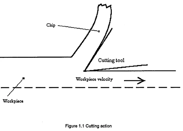
Sawing is the process in which chips are formed by a succession of small cutting edges, arranged in a narrow line on a saw "blade". Appendix 1 discusses the different sawing processes. To facilitate the sawing process, various motions and forces are required. The feed motion and feed force causes the tips of the teeth to penetrate the workpiece (figure 1.1). The cutting motion causes the sawing which ensures chip removal. The sawing rate varies with the feed rate and cutting speed. The sawing rates are limited by the following
factors:-a. The material to be cut e.g. uniformity and hardness. b. The saw blade material.
c. The heat treatment of the cutting edge. d. Feed per tooth.
Chip
Cutting tool
Workpiece velocity ■
[image:15.612.145.449.78.296.2]Workpiece
Figure 1.1 Cutting action
The properties of material to be cut, those of the saw blade material, and the heat treatment of the cutting edges all greatly affect the cutting speed. Soft steels and non ferrous metals may be cut at relatively high speeds. This can prevent the teeth clog in the workpiece. With increased alloying of the workpiece ,or heat treatment increasing material hardness, the cutting speed must be reduced [1]. This is because more cutting force is required to perform the operation, hence the temperature increases. In order to maintain the tool life, cutting speed must be reduced.
Heat treatment of the saw blade cutting edges increasing their hardness permits higher surface speeds. However a high degree of heat treatment will increase the susceptibility to fracture of the cutting edge. By contrast, a hardened high speed steel or a bimetal tool is considerably less sensitive [1]. This is because the saw blade is tougher than heat treated saw blade.
C. Abrading
The abrading tool presents a series of multi-point cutting tools to the work. The size of the chips removed depends upon the grit size used in the cutting tool. Therefore a fine grit should be used for finishing operations as it will remove finer chips and leave a smoother surface finish.
The ideal cutting action is achieved when the work is wearing away the bond at the same speed as the grains are dulled. Hence the dulled grains are torn away, exposing fresh grains. This action is known as 'self sharpening'.
1.4 Problems in selecting cutting-off processes
Sawing is the most widely used method for performing the cutting-off process. Sawing machines that perform this function include handsaws, hacksaws and circular saws. Different machines have different speeds, material losses, surface finish and power consumption. Therefore the choice of a cutting-off process can be a complex one and to complicate the choice, there are non-sawing techniques available for cutting materials. Whereas all sawing involves the cutting action of a series of small teeth, other basic machining methods can be adapted so that essentially the same job can be accomplished.
Power hacksawing is characterised by the reciprocating action of a relatively short, straight toothed blade that is drawn back and forth over the workpiece in much the same manner as a hand hacksaw. It differs from other sawing methods in that the back-and-forth motion of the blade makes a non-continuous cut.
Circular sawing machines are used exclusively for cut-off operations. The work is positively clamped and the saw blade fed into the work. The machine should have the necessary speeds and feeds to cover the range of work to be cut.
Band sawing machines are considered more versatile than any sawing machine previously discussed. They can perform simple cut-off, cutting along straight, curved lines. Band saws employ the continuous cutting action of an endless high speed toothed blade. Band saw machine can be classified as vertical machines (for straight and contour sawing), horizontal machine and vertical machine (used exclusively for friction sawing). More and detailed description of cutting-off process is given in Appendix 1.
the following factors:
i. Long term research into the machining processes associated with cutting-off have not yet produced comprehensive and widely applicable process parameters.
ii. There has been no attempt to collate and assimilate the body of knowledge used for cutting-off process selection purposes.
iii. Manufacturers regarded cutting-off process as a low level (technically) process.
Due to these problems, the cutting-off machine suppliers are dependent upon qualitative data and experience from tool manufacturers and users in order to select the appropriate process and cutting conditions.
In selecting cutting-off processes for a range of materials and cross sections, the manufacturing engineer is faced with many options. Currently, selection is based upon individual experience, knowledge, tool suppliers recommendations and known machine capabilities. The engineers approach to problem solving in these processes has been intuitive rather than systematic .
Each process has its own characteristics, the selection activities involve matching the requirement of the workpiece with the process capabilities of the selected processes. Selection of a particular cutting-off process depends not only on the parts to be cut-off but also on a large number of other factors. Some processes can cause change in the properties of the workpiece. Size, thickness and shape complexity of the part have a major bearing on the process selected to produce it. Before considering the type of cutting-off process or the saw type, the requirements of the operation should be carefully defined. For example, what productivity is required, how important is the surface finish, squareness, is the kerf loss (width of cut) critical, what space and power are available, workpiece configuration, material, size, weight, metal removal rate, tolerance etc.. This specification should then enable the basic process type to be identified, if not the actual saw type. Both the machine and saw manufacturers should be asked to recommend a suitable combination. If a particular process is found to be unreliable for producing the accuracy or surface finish required, another process must be chosen.
Sometimes these factors are closely related and the influences of quality on selection possibilities is an important consideration. For fast metal removal rate, fast cutting speed and feed will leave a poor surface finish on the workpiece compared, with a fine feed.
with automation devices. Therefore the approach of process selection and manufacturing cost must be considered and balanced.
It is now widely accepted that a systematic approach to problem solving is needed for routine use. The program designer must implement a set of specific objectives for investigating the needs and circumstances of the selection activity, and the synthesise these selection objectives into an optimum solution. The manufacturing engineer and sometimes the machine operator builds up a pool of knowledge and experience over time; this is used to select cutting-off processes.
Chapter 2
Literature Review
2.1 Introduction
This chapter reviews the existing cutting-off processes, expert systems in related selection work and cutting-off process selection.
2.2 Cutting-off process selection
K. Ishli, C. H. Lee and R. A. Miller [5] pointed out many handbooks which provide a qualitative guidance in selecting a process. However they do not provide a systematic means of comparing the suitability of each process for a given specification. Therefore many engineers select a process based on their experience, trial and error and testing programmes.
The major factors that influence the selection process are: a. Workpiece material condition
b. Tolerance c. Surface finish d. Kerf loss
e. Workpiece material f. Part shape and size
These factors are normally referred to as the functional requirements [5].
Before discussing the process selection method, it is useful to give a brief summary of how each major factor affects process selection:
a. Material condition
700 100 yo 80 c ■ p 3 O') 25 (id _1
„ L ______ 1 - .
200 100
[image:20.618.190.405.22.245.2]Tifinpcruture ( !' •
Figure 2.1 Hardness of various tool materials as a function of temperature [1].
b. Tolerance
Different cutting-off processes have different tolerance limitations (figure 2.2). In fact, there is a range of tolerances for which each process can be employed most economically. It is noted that tolerances are usually derived from mechanical, environment or aesthetic requirements.
Tolerance (mm) A •0.3 -0.4 -0.5 Pow er H acksaw Abrasive Saw ing m
L aser Beam Cutting
HP
W aterJet Cuttingmm
Circular S awOxyfuel G as Cutting
Cutting
Cutting-off processes
Figure 2.2 Different cutting-off process tolerance range [6, 13, 14].
8
[image:20.618.107.513.393.652.2]c. Surface finish
There are many types of surface finish specifications, and each process has its limitation (figure 2.3). This can also be effected by speed and feed rates used in the processing.
1000
500
Surface roughness ( frm)
A
200
Abrasive Sawing
mmm
Power Hacksaw
Bandsaw
Laser Beam
Wateijet Cutting
Circular Saw
Arc Cutting
[image:21.612.104.535.98.416.2]Cutting-off processes
Figure 2.3 Different cutting-off process surface finish ranges obtainable [6, 13, 14].
d. Kerf loss
The cutting-off process removes material in the form of chips. For economical use of material, the width of cut (kerf loss) must kept to as small as possible, minimising material waste. Each process has its limitations (figure 2.4).
Kerf loss (mm)
A
2010
9
8
7
6
5
4
3
2
1
0
Oxyfuel G as Cutting
Abrasive Sawing
m
Power Hacksaw
Laser Beam Cutting Bandsaw
Waterjet Cutting
[image:22.621.117.509.34.279.2]Cutting-off processes
Figure 2.4 Kerf loss of different cutting-off process [6, 13, 14]
e. Material
The physical properties of the material to be cut have a major effect on the part design, tooling, feed and speed rates used and the capacity of the sawing machine required. Their influence on the type of machine is generally minimal [6]. The material is primarily dependent on the physical and mechanical properties required [5]. In actual practice, the properties are considered are strength, hardness, and stiffness/ weight ratio. These material properties directly influence the production methods by which the material is worked.
f. Part shape and size
Both the size and geometry of the stock to be cut are important considerations because they determine the machine capacity and affect the type of sawing machine and process to be used [6].
Early published work (before 1970) on cutting-off process are concerned with a general description of the power hacksawing, circular sawing and bandsawing [7, 8, 9] and comparisons between these alternative processes [10, 11, 12]. From cutting-tool manufacturer's recommendation and handbooks [13, 14], the manufacturing engineer can select the cutting-off process and tools.
2.3 Reported uses of expert systems for selection tasks
Expert systems have provided business organisations with practical solutions to complex problems over the last decade. As computers increase in power while costs decline there is an increasing expectation that high volume low-level decision making will be delegated to machines releasing people for low volume high level decision making. These are factors which conventional computer systems cannot handle. The number of companies that use expert systems has grown significantly in the past few years, and many more organisations are now introducing them. Expert systems technology is receiving attention from industry, commercial businesses, as well as medical concerns and government departments because of its potential to help solve previously intractable problems and increased competitiveness.
Expert systems allow companies to save time and money, distribute and preserve expertise, build upon knowledge, and as a result gain competitive advantages. The term expert system is taken to include the full range of techniques available to provide solutions to the machining process problems of planning, parameter selection, optimisation, parameter identification, monitoring, decision making and operational control [15].
Many expert system projects already have been completed in various related applications such as scheduling, cutting tool selection and robot gripper selection dtc..
Hyuk-Soo Jang and Amit Bagchi [16] attempted to combine the information from the part design and manufacturing data bases on machining processes, and use this knowledge base to select the parameters for milling, drilling, boring and other machining processes. The selection and use of the data bases can be done in several ways. Firstly, by manual examination of the data and selection of the appropriate speed and feed rates. A second possible method is more automated, it is to interface the data base manager with a rule based system to select the feed rate and speed. The data bases contain information regarding tool materials, workpiece materials, tool geometries and machining parameters for the milling, turning, boring and drilling processes.
Rules are the most popular technique for representing knowledge. In fact, they provide a formal way of presenting recommendations, directives or strategies. Rules are often appropriate when the domain knowledge results from empirical associations, which have been developed through years of experience of solving problems in an area [18].
W. A. Taylor [19] describes how welding engineers produced welding procedure. Initially, all relevant information about the weld is collected, such as the material thickness, and parent metal composition. Depending on the welding position and material, the knowledge is used to narrow down the options and select the most appropriate welding process.
R. Razfar and K. Ridgway [20], have aimed to use expert systems to replace humans in the selection of cutting tools and conditions for milling. Different kinds of milling process are involved in the knowledge bases, such as face milling and slot milling, etc.. The selection rules are elicited from books, technical catalogues and domain experts. The factors which effect the selection are: tolerance, geometric features, surface finish, workpiece material and machine tool characteristics. Minimum production cost or maximum production rate criteria are used in calculating the optimum machining parameters.
The first stage in their selection process is to identify a tool or tools which can mill the specified materials. The system uses geometry rules to identify the tools which are suitable for all features. The remaining tools are eliminated from the next stage of the process. After all the tools have been selected, the appropriate cutter diameter and inserts for every feature are selected using rule based constraints. The final stage is to select the remaining parameters such as insert grade, tool holding system, number of inserts and chip space.
The first level is to provide tools which can produce the required geometry and machine the workpiece material efficiently, whilst satisfying all quality assurance considerations. Multiple tools are selected for each machining operation, and tool lists are formed by sorting selected tools in order of preference.
The second consideration is the tool replacement strategy. The main consideration at the second selection level provides a tooling solution for a component by considering all the operations required as well as the characteristics of the machine tool. The first objective of the tool replacement strategy is to machine an integer number of components with each cutting edge. The second objective is to balance the wear rates of tools so that tools are changed at optimal intervals and as many tools as possible are changed at the same time.
The third selection level is based on material orders and schedules produced by the material requirement planning (MRP) system. The selected tools are then rationalised by forming a set of tools for machining a variety of components on a given machine tool at level 3. When the number of tool positions on the machining centre is smaller than the total number of tools selected, the number of tools must be reduced so that it becomes equal to the number of tool positions and in this process geometric suitability is usually the first consideration.
The fourth level is multi-machine selection level which includes detailed considerations with regard to the layout of resources. It attempts to use common and standard tools within a group of machines. Having completed the first three tool selection levels, there is a set of tools allocated to each machine tool for machining either a certain product (level 2) or a product range (level 3) over a given period of time [21].
The fifth level is very much a planning phase and its various functions have widely different time cycles. The main objectives of the fifth level are to reduce tool inventory by classifying existing tools into categories according to their usage . This level is also used for introducing new tools into the manufacturing system, and to define the overall tool requirements and manage the efficient allocation and distribution of tools to machining resources.
The selection of a cutting-off parameters from the knowledge base can be achieved in several ways. One may, for instance, scan a section of the data manually and select the most appropriate speed and feed rate. The expertise of the user plays an important role here because the choice between a higher feed rate and a low speed or a lower feed rate and a higher speed combination (both of which can have the same material removal rate), for example, has to be made [23].
Metal removal rate = Cutting speed * Feed * Depth of cut
If depth of cut is kept constant, the cutting speed and feed varies, it can obtain the same metal removal rate.
The second method is a more automated method. The cutting-off parameters are saved in a spreadsheet program, which interfaces with a rule based system to select parameters including the speed, feed rate and cutting tool pitch. For this research, the second approach was adopted in order to automate the process and parameter selection, making its results less error prone and more consistent with different users.
2.4 Reasons for using an expert system in preference to conventional program
Expert systems attempt to produce results identical to such as those produced by people. Computers already emulate some of the simpler activities of the human mind, greatly speeding up some aspects of the human thought process, and usually exceed humans in performance. Expert systems enable us to go further: and allow us to automate or enhance more complex tasks which are normally only carried out manually [25]. For example, Davy Mckee is using an expert system for designing rolling mill instead of manual designing process. The expert system contains the equations and informations needed for designing the rolling mill. The solution come out in several minutes by expert system. The manual process takes several days to calculate the equation (such as roller size, roller distance) and look through the informations to arrange the bearings and its accessories.
Expert systems have several advantages over human knowledge [25].
a. Artificial intelligence (AI) is more permanent. If humans change their places of employment or forget information, it causes a knowledge loss. AI, however, is permanent as long as the computer systems and programs remain unchanged.
c. AI can be less expensive than human knowledge. There are many circumstances in which buying computer services costs less over a long period compared with having corresponding human experts to carry out the same tasks.
d. AI, being a computer technology, is consistent and thorough. Human knowledge is erratic because people are erratic; they do not perform consistently.
e. AI can be documented. Decisions made by a computer can be easily documented by tracing the activities of the system. Human knowledge is difficult to reproduce.
There are several reasons of using artificial expertise to assist the practitioners [25].
a. Artificial expertise is permanent, whereas human expertise can quickly fade, whether it involves mental or physical activity. The expert needs continuous work to maintain his/ her professional knowledge in an area, but artificial expertise is not related to its use. b. Once an expert leaves the company his expertise is lost, however this does not apply to the
artificial expert.
c. Artificial expertise is easy to transfer [26]. Data can be copied from one computer and installed into another computer.
d. Artificial expertise gives more consistent results than the human expert, who may make different decisions in the same situation because of emotional factors [27].
e. The most obvious advantage is the cost; human experts are very scarce and are therefore very expensive. Expert systems are relatively inexpensive, they are costly to develop but cheap to operate [27].
f. Human experts do not explain why they make such decisions, but expert systems can provide explanations of the result easily. It is a straight forward mapping between the way in which the knowledge is represented in the system and the natural language description of the representation [27].
Reasons for using expert system rather than a conventional program
b. Expert systems use an inferential process to solve problems so that they can provide explanations for the decisions made [27].
c. Expert systems use a "rule of thumb" or other devices which simplify, or limit the search in large problem areas where conventional programs use algorithms [27].
Expert systems have their origins in traditional data processing. They are the result of continuous attempts to improve and extend the automation of some aspects of human information processing. In order to accomplish this task it is necessary to represent in a computer system the nature of the data and processes involved. An expert system uses knowledge, facts and reasoning techniques to solve problems that normally require the abilities of human expert.
Sometimes an expert system is called an "Intelligent Knowledge Based system". It is a computer system containing expertise in a particular area [26], If anybody has professional knowledge in a particular field, he can describe the problem solving method, and by using this method an expert system can be built.
An expert system is a program containing a large body of knowledge in one specified field. The program encodes the knowledge of experts and uses techniques other than conventional computer languages to represent that knowledge. This is provided by one or more human experts and the system is able to achieve the same performance in problem solving as those experts. Frequently, experts posses knowledge which is extremely valuable but which can not be expressed easily in conventional computer programs. Their knowledge often relies on experience from past situations which is reapplied when necessary to deal with a similar situation.
In general, this knowledge will be organised as a collection of rules that allow the system to draw conclusions from given data or premises [27]. It also acts as a diagnostic system: given an appropriate set of information it will make some form of judgement or recommendation. If it cannot do either of these, it will ask for further information which will help it to make such a judgement.
This system can help to solve problems that cannot be handled effectively by conventional systems. The types of problems that normally lend themselves to successful expert system solutions include diagnosis, configuration, planning, scheduling, selection, matching and routing. Many of these tasks have the characteristics listed below:
i. The problem cannot be solved easily using a conventional solution because (1) no algorithm is known for solving it completely, or (2) the problem is too complex to be presented in conventional programming languages. For example, Dustpro is a small rule based system developed by the U.S. Bureau of Mines [25]. This system can replace dust control engineer to re-evaluate and reassign facilitates each time operating conditions change. Dustpro advises in three areas: control of methane gas emission, ventilation in continuous operation, and dust control for the mine's machines [25].
ii. The problem requires primarily symbolic, not numeric, reasoning. For example, help desks are important in providing technical information about procedures and regulations. Due to the increased complexity and quantity of the stored information, traditional computerised solutions include searching database is becoming less effective. An expert system help desk is created at Harris Corp's headquarters [25], this help desk provides a hot line for employees to troubleshoot problems in computer hardware and networks. iii. A tool is needed to facilitate prototyping (building an early version of the application), for
recording later in a conventional language. For example, EXTELCSYS was built using rapid prototyping methodology [25]. This system contains fifteen rules and ten choices. It can determine: what type of instrument should be installed; what make; what model; if the line should be capable of receiving incoming calls from oftpost; how it should be installed depending on the required location within the medical centre; and a selection of user requirements [25], After the first prototype was tested, new rules, qualifiers, variables, values, choices, and so forth, were continually added until the basic features and/ or requirements known to the experts were included.
2.5 Expert system tool selection
Choosing a suitable expert system tool is a major decision in the development process. Different kinds of expert system tools are listed in appendix 2. The selection will depend on several important factors. For example, is the programming capability available in house, and which languages are used? What type of computer system will be used to develop the software and what is the user's host computer? The time and funds available to develop the software will also affect the selection of the tool.
A programmer should be able to write code quickly if he is familiar with the language.
If sufficient funding and time is available and other systems are also to be designed and built, it may be worthwhile to acquire expertise in LISP or PROLOG languages. LISP and PROLOG interpreters are available for almost any machine [25]. PROLOG has a built-in inference engine. The knowledge engineer need to format the knowledge in terms of facts and rules. LISP also has an inference engine, but with LISP knowledge engineer have to implement search, pattern- matching, and other system features from scratch [25].
The quickest and simplest approach is to use a shell. If this is the first expert system development project, a using shell is most suitable. This is because an expert system shell contains: inference engine, explanation facility, interface subsystem, knowledge acquisition subsystem, knowledge base management facility and knowledge base. The knowledge engineer encode the knowledge in the knowledge base then the shell can be used for many applications. There is no need to program the first five subsystem. If a shell is available for the computer and within the project budget, it is necessary to determine whether its capabilities match the problem. The programmer will need to undertake some knowledge engineering to determine whether the domain can be expressed properly in rule format.
Xi plus [28] is an expert system shell. Xi plus provide a complete development environment on micros. The user interface is rich of commands, you can ask why the system asks this question, volunteer information, temporary pause the consultation process to review the data. The developer interface can allow the rules delete, move or copy from the knowledge base, checker, advisers, tracing and cross referencing tools.
It uses standard rule "If...Then", the inference mechanism is forward and backward chaining as well as demons and some other quite complex control methods[28]. In Xi Plus, the knowledge base items such as facts, rules etc. are expressed in a form similar to simple natural language. [28] The knowledge base contains the domain expertise. It is also known as Rule Base, specially when expert system uses production rules (If... then ...) to represent knowledge. Since knowledge base is independent of the inference engine, any number of expert systems can be developed by creating knowledge bases for each application [28]. When production rules are used they can be appended to the knowledge base in any order. This permits the modular development of knowledge bases.
communicate and share data to each other [28],
Xi plus can display graphical image, retrieve data from lotus 1-2-3 and have some program interface such as Assembler, C and Basic [28].
Xi Plus is an expert system shell which can be embedded in any other software system is also available and in most expert system shells, knowledge items can be expressed in English.
The reasons of using Xi plus are:
1. Knowledge items can be expressed in English like a statements, such that it is easy for debugging and understanding the knowledge base.
For example,
IF number of wheels = 2 AND power source is engine
THEN vehicle type is two wheel motorbike
2. It can communicate with other software systems such as Lotus, Databases and graphics, etc.
3. It can be implemented in any type of computer system such as a main frame or a PC. 4. The knowledge base can be input by word processing so the spelling error can be
corrected before import to the Xi plus.
2.6 Conclusions
From the reported expert system for selection tasks, their attempts are success. Therefore it is a possible solution for using expert system in selecting cutting-off process selection and its parameters. Expert system shell (Xi Plus) have the ability to build up a prototype system to undertake this project.
Chapter 3
Cutting-off process selection: Industrial practice in U.K.
3.1 Introduction
Although the cutting-off process is used in all types of discrete manufacturing industry, different companies have different methods of selecting the cutting-off processes, tools and the cutting parameters. There is little published information available on how and what tools companies used to make these decisions and what type of cutting off processes are used by industry. Therefore a national survey carried out to obtain this information. This kind of information will be used in developing the selection prototype system.
3.2 Objectives of survey
Initially it is necessary to identify the real basis for the selection procedure, and also the current approaches to the selection process. Hence a U.K. national survey was undertaken to obtain the required information about the cutting-off process and practices. The companies involved are cutting-off process users, cutting-off tool suppliers and cutting-off machine tool suppliers. In the cutting-off process selection procedure, three major things need to be considered. They are the cutting-off processes, the cutting-off tools and the cutting-off machine tools. Therefore this national survey collected information on all these three categories.
3.3 Survey design
The "cutting-off" industry can be divided into two distinct sections, namely, (i) process user and (ii) the suppliers vendors. The suppliers can be further divided into machine tool supplier and cutting tool suppliers.
The survey was designed to elicit the following information from the categories shown:-1. Process user
It is necessary to determine the actual practice in U.K. industry, i.e. the most widely used processes, the most common machine types, ages of the machines, and the capacities and production practices in U.K. industry.
2. Cutting-off tool manufacturers
It is necessary to determine the types of cutting-off tools, materials and quantities produced. 3. Cutting-off machine manufacturers
3.4 Selection of the survey method
There are several methods for carrying out surveys, including telephone interviews, personal interviews, and mail questionnaires [29]. Telephone interviews and personal interviews can provide very accurate information and a high response rates however costs can be high. For personal interviews, it is difficult to cover all U.K. companies to get all the information as it would be very time consuming and expensive [29].
The postal questionnaire method is by far the cheapest method [29] but it has the lowest response rate (that is, only those most interested or highly supportive are most likely to respond) [30].
3.5 Design of questionnaire
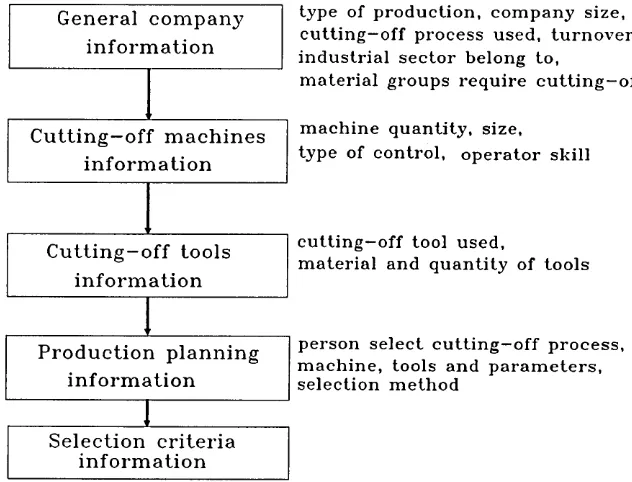
The problem was set out clearly and the logical implications see figure 3.1 for cutting-off process user, figure 3.2 for cutting-off tool manufacturer and figure 3.3 for cutting-off machine manufacturer. The questions are closely related to the problems under study. The questionnaire must not be too long because respondents would loose interest. Each complex question was broken down into further smallest questions, so that the questions were simple and straight forward in order to avoid ambiguity [31].
S e l e c t i o n c r i t e r i a i n f o r m a t i o n G e n e r a l c o m p a n y
i n f o r m a t i o n
C u t t i n g - o f f m a c h i n e s i n f o r m a t i o n
C u t t i n g - o f f t o o l s i n f o r m a t i o n
P r o d u c t i o n p l a n n i n g i n f o r m a t i o n
type of p ro d u ctio n , com p an y size, c u ttin g -o ff p ro cess u sed , tu rn o v er, in d u stria l se cto r b elon g to,
m a teria l groups requ ire c u t tin g - o ff
m a ch in e q u an tity, size,
type of con trol, op erator sk ill
c u ttin g -o ff tool u sed ,
m a teria l and q u a n tity of to o ls
[image:33.612.119.435.361.602.2]p erson s e le c t c u ttin g —o ff p ro cess, m a ch in e, to o ls and p a ra m eter s, se lec tio n m eth od
p r o v i d e s e l e c t i o n h e l p t o c u s t o m e r o r n o t
c u t t i n g - o f f t o o l r a n g e a n d q u a n t i t y c u t t i n g - o f f t o o l
m a n u f a c t u r e d
c u t t i n g - o f f t o o l m a t e r i a l G e n e r a l c o m p a n y
[image:34.614.203.349.50.265.2]i n f o r m a t i o n
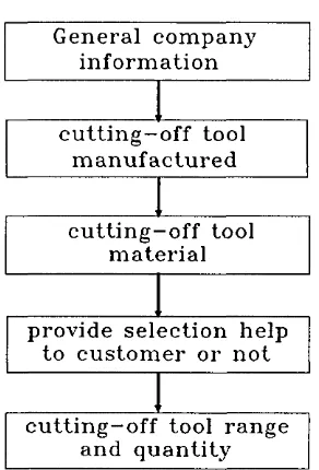
Figure 3.2 Cutting-off tool manufacturer questionnaire layout
i n f o r m a t i o n M a c h i n e G e n e r a l c o m p a n y
i n f o r m a t i o n
m a c h i n e p r o d u c e d a n d e x p e c t t o p r o d u c e
in n e x t y e a r
q u a n tity and type of con trol
[image:34.614.146.359.379.551.2]The questionnaire designed for process users is divided into the following sections: (All three types of mail questionnaires are attached in appendix 3)
Section 1 for collecting general company information. Section 2 for collecting information regarding the cutting-off machine tools. Section 3 is asking about the information regarding the cutting-off tools. Section 4 is asking about the methods used and the people who undertake the selection of cutting-off processes, cutting-off tools, machines and their parameters. Section 5 covers the selection criteria.
From the answers, the methods of selection used for the cutting-off processes, machines, cutting tools and parameters can be collated. Computer assistance or manual approaches and what the major cutting-off processes used in manufacturing industry can also be determined.
The questionnaire designed for cutting-off tool manufacturers is divided into the following sections:
Section 1 asks about the general company information. Section 2 is about their cutting-off tool information.
From this, it is possible to identify the major cutting-off tools used in the industry. Are coated tools extensively used by the cutting-off industry or are they still using H.S.S. cutting tools as their major cutting tool? This information could indicate the market trend in the use of cutting tools.
The questionnaire designed for machine tool manufacturer is divided into the following sections: Section 1 relates to general company information. Section 2 relates to the cutting-off machine tool information.
From the quantities of cutting-off machine production data in last financial year (1992 - 1993) and the expected production quantity in the next financial year (1993 - 1994), it is possible to determine the trend in the demand for cutting-off machines and also the trends in the use of cutting-off processes. It can provide the useful information for cutting-off tool and machine manufacturers.
select cutting-off machine tools? The possible answers include "manual, use of computer, use of external expert advise, other methods". If the response was "Use of computer", then the next question was "Please give the name of the package."
Since the questionnaires was divided into three categories, each of these set out to draw information from different group of respondents. The first categories was the process user, as this is the major part of the survey. This is because the manufacturing engineer is faced with the dilemma of specifying the manufacturing process and the cutting tools from an increasingly large number of available alternatives for part manufacturers. The manufacturing engineer is also faced with many different process specifications and a variety of alternative combinations of parts and cutting-off processes.
3.6 Survey data analysis
The data was transferred to a tabular format and then presented in graphical form. The statistical data is easy to present and quite straightforward. A frequency distribution table of the answers to each question was constructed. The frequency distribution table was input into a Lotus 123 spreadsheet [32] and then transferred to the Harvard Graphics package [33] to present the data in graphical form. The data was represented in percentages rather than frequencies. The purpose of using percentages is to make comparisons easier. It is important, therefore, to see exactly what their use implies so that they will not be misused. Firstly, it can serve to put qualitative characteristics into numerical form. Thus, it is possible to compare several cutting-off processes on the basis of use by saying that 16.7% use power hacksawing, 10.7% use abrasive cutting, etc. Secondly, percentages reduce two frequency distributions to a common base, thus making comparisons much simpler.
3.7 Survey results
The names of companies were obtained from the "Sell's Products and Services Directory" [34]. The reason for choosing this directory was that it was easy to access and it contained all types of industry in the U.K.. The postal questionnaire are presented in appendix 3.
All the graphs show the percentages of the responses in each answer categories, as a proportion of the total number. These are fully explained in each of the three categories of companies and the associated questionnaires in the next sections of this chapter.
3.7.1 Cutting-off Process user company
A total of one hundred and eighty four letters were mailed out for process users and twenty eight replies were received and seven responses did not meet the selection criteria such as they are not cutting ferrous or non ferrous steel, or were using lathe, cutter, drills, reamers for cutting, etc.. The response rate for process users was 15.2%.
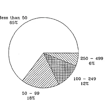
Figure3.4 shows the distribution of the number of employees in the companies who responded. The graph shows that most of the companies who responded employed fewer than 50 people. Figure 3.5 shows the distribution of industry sectors of the survey respondents. Figure 3.6 shows the types of production of the survey respondents. These product types are (i) job (38%), (ii) batch (13%), job and (iii) batch and customer dedicated (6%), (iv) job and commission and restoration (6%), (v) job and batch (38%).
le s s " —
250 - 499
6%
100 - 249 12%
[image:37.618.196.374.394.567.2]50 - 99 18%
Engineering 9%
Others 32%
Food processing
5% Aerospace 9%
Joiner Automative
9% Carpenter
5% Electronics
9%
Black &: bladesm ith 5%
Construction 5% Fluid sealing
5% Wood turner
Figure 3.5 Industry sector of the survey respondents
Job
B a t c h 13% , J o b + b a t c h
I
+ c u s t o m e r E d e d i c a t e d c e l l 6% 'J o b + b a t c h 6% + c o m m i s s i o n
+ r e s t o r a t i o n Job 4- b a t c h 38%
Figure 3.7 shows the types of personnel responsible for the selection of the cutting-off processes and Figure 3.8 shows the types of personnel responsible for for the selection of the cutting-off machines.
Production engineer \ 33%
Production planner
20% i
Supervisors+planner +=
7% \
Techician 7%
^7
Owner / 7%Manu. Director 7%
Figure 3.7 Personal responsible for selecting cutting-off processes
Production engineer \ 33%
Techician 7% A Owner a x
Manu. Director
7% Supervisors+planner
7% Operators
13% Engineer + foreman7%
Forge m aster
7% Production planner13%
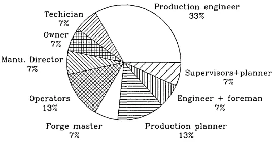
Figure 3.9 shows the types of personnel responsible for the selection of the cutting-off tools and Figure 3.10 shows the types of personnel responsible for for the selection of the cutting-off parameters.
Production engineer \ 33% Techician
7% A Owner
Manu. Director
7% Supervisors+planner
7% Operators
13% Engineer + foreman7% Production planner
[image:40.614.142.411.149.289.2]13%
Figure 3.9 Personal responsible for selecting cutting-off tools
Production engineer \ 29%
Production planner
2 1% /
Owner
7% Planner+ supervisor7% Manu. Director
7% s Techician7%
Forge m aster 7% Operators
14%
The largest percentage of people involved in the selection were production engineers. A total of 33% of cutting-off machine and cutting-off tool selection decision were made by production engineers and 29% of cutting-off parameters were selected by production engineers. It seems that the selection decision were made by people with a technical background. No company selected the cutting-off processes, machines or cutting-off tools using a computer based program. Most of them selected cutting-off machine by in house personnel (manually) (82%), and only 18% by external expert advice and in house manually together (figure 3.11). The cutting-off tools were selected by in house personnel 83%, external expert advice and in house manually together accounted for 17% (figure 3.12).
Manually
8 2%
Expert + Manually
18%
Figure 3.11 Resources used to select cutting-off machine
Manuall
83%
Manually + Expert
17%
Power Hacksawing
Abrasive cutting
Laser beam cutting ' / / / / / / / / / / / / / / / / / / / / / / / / / / / / / / / / / / / / / / / / A
Circular sawing
Arc cutting
Oxyfue] gas cutting
Others
20 40 60 60 100 120
0
Percentage (%) □ □ Manual E22) NC/ CNC
Figure 3.13 Types of cutting-off machine tools used by the respondents
Figure 3.13 shows the number of different cutting-off machines used by the various companies. The most widely used cutting-off machines are the circular sawing machine (25%), the oxyfuel gas cutting machine (20.2%), the bandsawing machine (17.3%) and the abrasive cutting machine (17.3%). Power hacksawing was only used by 10.6% of respondents.
C u ttin g -o ff process
Power hacksawing
Abrasive cutting
Bandsawing
Laser beam cutting
Circular sawing
Arc cutting
Oxyfuel gas cutting
Others
0 5 10 15 20 25 30
Percentage (%)
Figure 3.14 Cutting-off process employed by users
Figure 3.14 shows the proportions of each type of cutting-off processes used by the different
30
□
companies. Circular sawing (23.6%), bandsawing (21.8%) and power hacksawing (16.4%) were the major processes used by cutting-off process companies.
Circular saw
31% / \Power hacksaw
2 1%
Others 5%
Abrasive saw
12% Bandsaw
29%
Figure 3.15 Cutting-off tools used by survey respondents
The cutting-off tools used by cutting-off companies were circular saws (31%), bandsaw blades (29%), power hacksaw blades (21%), abrasive disks (12%), angle grinders (2%) and others (5%). These are presented in Figure 3.15. From these sets of data, it can be see that industry applies circular sawing and bandsawing operation more extensively than power hacksawing.
Carbide tipped tools
\ 24%
H.C.S. 4% H.S.S.
60%
Coated tools
12%
The materials for the cutting tools used by users companies (figure 3.16) were high speed steel (H.S.S.) (60%), carbide tipped tools (24%), coated tools (12%) and high carbon steel (H.C.S.) (4%).
Metals 70% .
Polymer 9%
Organics 13% Ceramics
Figure 3.17 Types of materials cut by survey respondents
The materials cut by users companies represented by figure 3.17 were metals (70%), organic (13%), ceramics (9%) and polymer (9%).
Qualified X 35%
Qualified Sem i-skilled
41%
Unskilled
6%
Nearly half of the cutting-off process companies used semi-skilled (on job training) operators to run the machines (41%) and 35% companies used skilled (trained) operators to run a cutting-off machine and 18% companies use both skilled and semi-skilled operator together to run a machine. A few companies used unskilled (non trained) operators to run a cutting-off machine (6%) (figure 3.18). Most of the cutting-off process companies use one operator for their cutting-off machines (59%) but some are operated by 2 (12%), 3 (18%), owner (6%) and operators which can operate several machines (6%).
3.7.2 Cutting-off tool manufacturer
A total of seventy questionnaires were mailed out for cutting-off tool manufacturers, thirty three responses were received and twenty two responses did not meet the selection criteria The response rate of cutting-off tool manufacturers was 47%.
Figure 3.19 shows the company sizes of cutting-off tool manufacturer companies. The graph showed that most of the companies in U.K. (64%) employed fewer than 50 people in their company.
l e s s t h a n 5 0 64% /
5 0 0 - 9 9 9 9%
1 0 0 - 2 4 9 0%
5 0 - 9 9 27% 2 5 0 - 4 9 9 0%
Circular saw blade
22%
Bandsaw blade
28%
Power hacksaw blade
\ 1 1%
Others
22%
Abrasive disk
17%
Figure 3.20 Types of cutting-off tool manufactured by cutting-off tool companies
Figure 3.20 Shows the types of cutting-off tools manufactured by cutting-off process companies. These include bandsaw blades (28%), circular saw blades (22%), abrasive disk (17%), power hacksaw blades (11%) and others (22%). The use of circular saw blades and bandsaw blades were both higher than the power hacksaw blades, this figure confirms the previous sections findings that most widely used processes were the circular and bandsawing ( figures 3.13 and 3.14).
H.S.S.
26%
Abrasive grain
5%
Carbide tipped tools
3 2% Coated tool
11%
Aluminium oxide
5% H.C.S.
i 11% Others
1 1%
Figure 3.21 shows distribution of the materials used for the cutting-off tools. These include carbide tipped tools (28%), H.S.S. tools (28%), H.C.S. tools (12%), coated tools (12%), abrasive grain (5%), aluminium oxide (5%), others (11%).
A total of 82% of cutting-off tool manufacturers provided cutting-off parameter data and tables for their customers which were based on their products.
3.7.3 Cutting-ofT machine manufacturer
A total of one hundred and thirty five questionnaires were mailed out for cutting-off machine manufacturers and thirty five responses received and twenty two responses did not meet the selection criteria. The response rate of cutting-off machine manufacturers was 26%.
Figure 3.22 shows sizes of the different cutting-off machine manufacturers. The graph showed that most of these companies in the U.K. (75%) employed fewer than 50 people.
l e s s t h a n 75%
5 0 - 9 9 25%
M a c h i n e
P ow er h a c k sa w in g
A brasive c u ttin g
L aser b e a m c u ttin g C ircu lar saw in g
Arc c u ttin g
'//////////)/////////////777/////////A
O xyfu el g a s c u ttin g
O th ers
20 60
0 40 80 100
P e r c en ta g e (%)
1 I M anual \//A N C / CNC
Figure 3.23 Types of cutting-off machine produced by machine manufacturers
Figure 3.23 shows the number of cutting-off machines and the types of controls for the machines produced in the last financial year by various cutting-off machine manufacturers. They produced a large quantity amount of handsaws (301) and circular saws (213). Again this confirm both the findings of the wider use of circular and bandsawing processes by industry (figure 3.14), use of circular and bandsawing machine tools by industry (figure 3.13) and the cutting tools for these processes (figure 3.20) in previous sections.
3.8. Discussions
The response rate for three parts of the survey are not very high, especially the cutting-off process user and cutting-off machine manufacturer; this might be for several reasons. Firstly, some of the companies had moved or closed down. Secondly, a reminder letter had not been sent out to keep trace of the respondents and thirdly, some of the respondents had no interest in making any contribution to this survey.
The selection of cutting-off processes and the machines, tools and cutting parameters involved is usually performed by experts with the relevant knowledge, such as production engineers. The responses show that, in some firms, technicians or operators are involved with making these decisions. Adequate knowledge and experience is required for this task.
Power hacksawing was once the most commonly used method for cutting off workpieces. However, this has recently been superseded by the process of bandsawing and circular sawing. New technology has enabled these methods to provide superior surface finishes, dimensional tolerances, production rates, kerf losses and squareness of cuts; compared with power hacksawing. The survey data from the users (figures 3.13 and 3.14) shows that bandsawing and circular sawing are now the preferred methods for cutting-off. The data for the types and quantities of cutting off machines produced (figure 3.23) supports this conclusion.
No companies used NC/ CNC sawing machine to perform their cutting-off processes. The only type of NC/ CNC machine used was the laser beam cutting machine. This was because it can conduct profile cutting which is more accurate than the manual operation.
Most of the respondent companies still use H.S.S. tools as their cutting-off tool material (figure 3.16). This is possibly because it is cheap, suitable for general cutting-off and it can be reground repeatedly before being discarded. Carbide tipped tools and coated tools are suitable for special purpose and hard material (i.e. Vickers hardness > 400) which can not be machined by H.S.S. tools.
The analysis of the result was limited, due to the small number of returned questionnaires from the respondents, but in spite of that, some interesting conclusions have been found. The three types of questionnaires had an extremely high degree of positive cross-checking and consistency indicating a high degree of accuracy of the survey findings.
From the survey, it is found that most companies select the cutting-off machine (figure 3.11) and cutting-off tool (figure 3.12) manually (in house personal). When this person leave the company, it can cause a loss of knowledge.
![Figure 2.1 Hardness of various tool materials as a function of temperature [1].](https://thumb-us.123doks.com/thumbv2/123dok_us/8007580.763411/20.618.107.513.393.652/figure-hardness-various-tool-materials-function-temperature.webp)
![Figure 2.3 Different cutting-off process surface finish ranges obtainable [6, 13, 14].](https://thumb-us.123doks.com/thumbv2/123dok_us/8007580.763411/21.612.104.535.98.416/figure-different-cutting-process-surface-finish-ranges-obtainable.webp)
![Figure 2.4 Kerf loss of different cutting-off process [6, 13, 14]](https://thumb-us.123doks.com/thumbv2/123dok_us/8007580.763411/22.621.117.509.34.279/figure-kerf-loss-different-cutting-process.webp)