5
III
March 2017
Technology (IJRASET)
©IJRASET: All Rights are Reserved
589
Design of High Pass FIR Filter using Rectangular
and Taylor Window Method
Hardip Miri1, Yogendra Karsh2,Rahul Suryawanshi3, Rajesh suryawanshi4, Pranay Kumar Rahi5 1,2,3,4,5
Department of Electrical and Electronics Engineering , 5Guru Ghasidas University, Bilaspur Chhattisgarh
Abstract: In this paper a window function has been defined and simulated. In the initial section the frequency response of the four basic types of FIR filter have been simulated using the window function. Then the fir filter responses are compared with those using Taylor window and Rectangular window function. Improved frequency response have been observed, the frequency response of the new window function will be compared with other common window function in near future with generalized and quantized experimental results.
Keywords: DSP, Digital Filter, High Pass Filter, FIR, Rectangular Window and Taylor Window.
I. INTRODUCTION
Signal processing is a method of extracting information the signal which in turn depends on the type of signal and the nature of information it carries. Thus signal processing is concerned with representing signals in mathematical terms and extracting the information by carrying out the algorithmic operation on the signal [1].
Digital processing of a signal facilitates the shearing of a signal processor among a number of signal by time- shearing .This reduces the processing cost, size, weight and maintenance per signal. Also DSP can save both filtered and unfiltered data for further use [2]. A digital filter is a mathematical algorithm implemented in hardware/software that operates on a digital input to produce digital output. Digital filter play very important roles in DSP [3].
A. Advantages
1) Digital filters can have characteristics are not possible with analog filters such as linear phase response.
2) Several input signals can be filtered by one digital filter without the need to replicate the hardware.
3) Digital filters can be used at very low frequencies.
B. Disadvantages
Speed limitation , Finite word length effects and Long design and development time.
C. Applications Of DSP
1) Signal Processing Applications: There are numerous applications of signal processing that we often encounter in our daily life
without being aware of them. Originally the signal processing algorithms used in these applications were carried out in the continuous time domain. It is not possible to discuss all of these applications. However an overview of selected applications is presented.
a) Sound Recording Application: The recording of most musical programs now a day is usually made in acoustically inert studio.
The sound from each instrument is picked up by its own microphone closely placed to the instrument and is recorded on a single track in a multi-track tape recorder containing us many us 48 tracks. The signals from individual tracks in the master recording are then edited and combined by the sound engineer in a mix-down system to develop a two-track stereo recording.
b) Telephone Dialing Application: Signal processing plays a key role in the detection and generation of signaling tones for
push-button[DAR76]. Seven frequencies are used to code the 10 decimal digits and the two special buttons marked “ * “ and “ # “ . The low – band frequencies are 697 Hz, 770 Hz, 852 Hz, and 941 Hz. The remaining three frequencies belonging to the high band are 1209 Hz, 1336 Hz and 1477 Hz.
c) FM Stereo Applications: For wireless transmission of a signal occupying a low frequency range, such as an audio signal, it is
©IJRASET: All Rights are Reserved
590
II. WINDOWMETHOD
These are the window method frequency sampling method and optimal or minimax design. The window method involves a straight forward analytical procedures, however, in some cases, iteration is necessary to obtained the desired results. Several windows are considered.
A. Rectangular Window
The relation expressed in equation can also be obtained by multiplying the sequence hd(n) by the sequence wR(n) defined by
WR(n) = 1 00 ≤ ℎ≤ −1
because of its appearance WR (n) is called rectangular window.
B. Taylor Window
[image:3.612.161.441.288.658.2]The Taylor window function for total number of samples, N = 10 is shown in figure. The sample points (n) are indicated along x – axis and the corresponding amplitude levels along y – axis respectively
Table 1: Parameter Specification.
C. Simulation and Result
[image:3.612.167.447.403.551.2]
Table 2: Filter Magnitude of Rectangular and Taylor Window Technique .
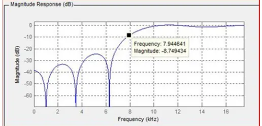
Figure 1: Magnitude response of Rectangular Window Technique.
PARAMETER VALUES
Sampling Frequency(fs) 35000
Cut off Frequency(fc) 8200
Order(N) 10
S. No. Frequency
Window Method
Rectangular (In dB)
Taylor (In dB)
1. 0.1 9.5502 9.6756
2. 0.2 7.0171 7.8320
3. 0.3 5.0901 -9.7399
4. 0.4 3.0329 -9.5389
5. 0.5 2.9796 -10.8655
6. 0.6 1.0134 -11.6542
[image:3.612.177.435.582.706.2]Technology (IJRASET)
[image:4.612.190.424.383.519.2]©IJRASET: All Rights are Reserved
591
Figure 2: Phase response of Rectangular Window Technique.
Figure 3: Filter coefficient of Rectangular Window Technique.
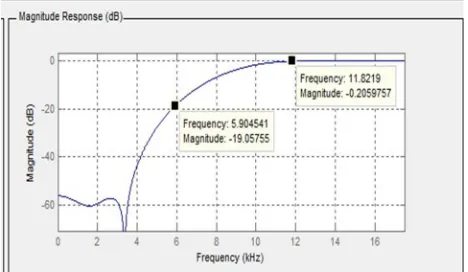
Figure 4: Magnitude response of Taylor Window Technique.
©IJRASET: All Rights are Reserved
592
Figure 6: Filter coefficient of Taylor Window Technique.
Figure 7: Magnitude and Frequency plot of Rectangular Window Technique.
Figure 8: Magnitude and Frequency plot of Taylor Window Technique.
III. CONCLUSIONS
Technology (IJRASET)
©IJRASET: All Rights are Reserved
593
IV. ACKNOWLEDGMENT
I am greatly thankful to Mr. Pranay Kumar Rahi (Registrar & Assistant Professor, Department of Electrical & Electronics Engineering, I. T. KORBA) The authors would thank the Electrical and Electronics Engineering. Department of the institute support and facilities to be provided during the research and simulation work.
REFERENCES
[1] Sanjit K. Mitra “digital signal processing” a computer based Approach 2nd Edition McGraw Hill, pp.1.
[2] Michael Weeks, “digital signal processing” Using MATLAB and Wavelets, 2007 edition, Infinity Science Press, pp. [3] S Salivahanan, C Gnanapriya, A Vallavaraj, “digital signal processing” Tata McGraw-Hill, 2nd Edition pp.3.443-448 [4] John G. Proakis, Dimitris G. Manolakis, “digital signal processing” PEAESON, fourth edition
[5] Sen M Kuo, Bob H Lee, “digital signal processing” John Wiley & Sons, 2001 edition [6] Richars G. lyons, Understanding digital signal processing” PEARSON, second edition [7] A Nagoor Kani, “digital signal processing” McGraw-Hill Education, second edition
[8] Alan V. Oppenheim, Ronald W. Schafer,“digital signal processing”, PEARSON education, 2015 edition [9] Steuen W. Smith, “digital signal processing”, Elsevier, 2005 edition.
[10] Emmanuel Ifeachor, Barry W. Jervis, “digital signal processing” PEARSON, second edition.
AUTHOR DETAILS
Pranay Kumar Rahi received the Bachelors of Technology in Electronics and Telecommunication Engineering from Government Engineering College, Guru Ghasidas University, Bilaspur, Chhattisgarh India in 2004, and pursuing Masters of Engineering from National Institute of Technical Teacher’s Training & Research, Punjab University, Chandigarh, India. Presently working as Assistant Professor in Department of Electrical and Electronic Engineering, Institute of Technology Korba, Chhattisgarh since 2008. He has authored more than 14 research publications and published Journal papers in the leading International and National journal. His primary research interest includes Digital Signal Processing,
VLSI Design, Control Systems and Digital Electronics and logic design.
Rahul Suryawanshi pursuing Bachelor of Engineering in Elecctrical and Electronics Engineering in 7th semester, from Institute of Technology Korba, Chhattisgarh Swami Vivekananda Technical University, Bhilai, Chhattisgarh, India.
Hardip Miri pursuiing Bachelor of Engineering in Electrical and Electronics Engineering in 5th semester, from Institute of Technology Korba, Chhattisgarh Swami Vivekanand Technical University, Chhattisgarh, India.
Yogendra Karsh pursuiing Bachelor of Engineering in Electrical and Electronics Engineering in 5th semester, from Institute of Technology Korba, Chhattisgarh Swami Vivekanand Technical University, Chhattisgarh, India.
Rajesh Suryawanshi received the Bachelors of Engineering in Electrical and Electronics Engineering from Institute of Technology Korba College, Chhattisgarh Swami Vivekananda Technical University, Bhilai, Chhattisgarh, India.