6
I
January 2018
Optimum Depth of Foundation for a given Soil
Profile
Sai Harshita M M1, A K Bharadwaj2
1
Assistant Professor, Department of Civil Engineering, Einstein College of Engineering, Tirunelveli
2
Assistant Engineer, Atkins Global, Bangalore
Abstract: The responsibility of a geotechnical engineer is to determine the location of foundation at which it will not only be safe but also economical. Safe design is now achieved by software’s which are available to carry out design without committing any numerical mistakes. For a particular problem, there can be several feasible designs from the point of view of safety and functional performance, but only one will be economical. In this project, an attempt is made to find the optimum depth of foundation for various soil profiles. For each of the designed foundations at various levels, the total cost is found and the most economical one is determined. Based on many numerical examples, it is concluded that in most of the cases, a smaller footing at a deeper depth is more economical than a larger footing at a shallower depth. However, this cannot be generalized. If a compressible clay layer is encountered below cohesion less layer, a footing laid at a shallower level may be economical compared to that at deeper level because for the latter case, the significant pressure bulb crosses the compressible clay layer.
Keywords: Compressible clay layer, N values, pressure bulb
I. INTRODUCTION
A foundation is a lower part of a structure which transmits load directly into the underlying soil. If the soil below the structure is sufficiently strong and capable of supporting the required load, then shallow foundations can be used [1]. If the soil conditions at the shallow depth are weak, then deep foundations are more suitable. Geotechnical engineering is the discipline that deals with soil properties to establish the allowable bearing capacity of footings[2]. Geotechnical engineers are members of design team who provide this information.
A confusion arises in the minds of geotechnical engineers in determining the location of foundation at which it will not only be safe but also economical. For a given soil profile, there are many locations at which a shallow foundation can be designed so that it satisfies the requirement [3]. But, there is only one location at which the foundation is the most economical one.
II. OBJECTIVE AND SCOPE OF STUDY
The objective of this study is to locate the depth of shallow foundation in the given soil profile and soil properties where it is not only safe but also economical and optimum design of footings subjected to generalized loadings taking into considerations of all the structural and geotechnical engineering aspects. In this project, it is proposed a study is carried out to find the optimum depth of foundation for the soil profiles given below:
A. Sandy layer with N value increasing along the depth[4]
B. Sand underlain by clay layer
III. PARAMETERS FOR DESIGN OF FOUNDATION A. Breadth Of The Footing
1) In the design of breadth of the foundation, the breadth is calculated so that it has a factor of safety of not less than 2.5 and its settlement is not more than 40mm.
2) The pressure corresponding to a settlement of 40mm can be calculated by the following formula given by Teng[5]
qsett =5.54 N-3
. ²×R
where,
N - The standard penetration test value B - The size of footing in m
qsett - Bearing pressure corresponding to a settlement of 40mm in t/m²
3) Bearing capacity from shear criteria using Teng’s equation as qnu = (3(100+N²)Df*R1+N²*B*R2)/30
where,
qnu-Net ultimate bearing capacity in t/m²
Df- Depth of footing in m
B- Size of footing in m but limited to Df
R1,R2- Water table correction factors
4) For sand underlain by clay, the significant pressure bulb comes into picture.
B. Influence Zone
Whenever a foundation is loaded, a pressure (stress) increase occurs in the underlying soil immediately below the footing. Actually the pressure spreads laterally to a certain extent as well. The intensity of pressure decreases with depth until it eventually becomes too small and is of little concern. The increase in pressure extends to a greater depth below larger footings than smaller footings, hence the depth is influenced by the width of the footing (B).The zone where the pressure increase is significant with respect to settlement varies with the width of the footing. For compressible soils such as clay however, the pressure increase is considered significant until the pressure increase is less than 10% of the effective overburden pressure.
C. Influence Of Water Table
The change in moisture content of the soil affects the properties of the soil. Similarly, if soil gets submerged its ability to support the load coming over its unit area is reduced. When the water table is above the base of the footing, the submerged weight is used for the soil below the water table for computing the surcharge. The water table corrections are applied to determine the ultimate bearing capacity of the soil.
D. Thickness Of The Footing
Thickness of the foundation is governed by punching shear, one way shear and bending moment criteria.
E. Amount Of Reinforcement
1) The reinforcement is provided from the moment [6], [7]
Area of steel reinforcement, Ast =0.5×
fck
fy
× 1- 1- 4.6×Mu
fck×B×d² ×B×d
2) Provided reinforcement should be greater than minimum requirement of steel
Astmin = (0.12/100)*b*D
IV. DESIGN OF FOOTING A.Sandy Layer With Increasing N Values (Example 1)
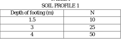
[image:3.612.189.424.594.670.2]The given soil profile which contains sand layer
TABLE I SOIL PROFILE 1
Depth of footing (m) N
1.5 10
3 25
4 50
Table II
Size of footing and reinforcement details SIZE OF THE
FOOTING DEPTH (mm) Ast (mm²) SPACING (mm) NO.OF BARS
3.0m*3.0m 450 3598 95 24
1.6m*1.6m 400 1271 140 11
1.0m*1.0m 330 751 150 7
[image:4.612.179.437.367.440.2]The estimated cost of various footings placed at various depths are as follows,
Table III Cost estimation
FOOTING SIZE ESTIMATED COST(Rs.)
3.0m*3.0m 18645
1.6m*1.6m 7118
1.0m*1.0m 3872
B. Sandy Layer With Increasing N Values (Example-2) The given soil profile which contains sand layer
Table IV Soil profile 2
Depth of footing (m) N
1 15
2.5 30
4 50
For the above profile , the size of the footing and the reinforcement required for each footing is as summarized below,
Table V
Size of footing and reinforcement details SIZE OF THE
FOOTING DEPTH (mm) Ast (mm²) SPACING (mm) NO.OF BARS
3.0 m*3.0 m 450 3598 95 24
1.4 m*1.4 m 440 1013 155 9
1.0 m*1.0 m 330 751 150 7
The estimated cost of various footings placed at various depths are as follows,
Table VI Cost estimation
FOOTING SIZE ESTIMATED COST(Rs.)
3.0 m*3.0 m 17501
1.4 m*1.4 m 5301
[image:4.612.107.509.501.574.2] [image:4.612.61.545.626.725.2]C. Sand Underlain By Clay layer (example-3) The given soil profile which contains sand layer
Fig.1 Soil profile 3
For the above profile , the size of the footing and the reinforcement required for each footing is as summarized below,
Table VII
Size of footing and reinforcement details SIZE OF THE
FOOTING
DEPTH (mm)
Ast (mm²)
SPACING (mm)
NO.OF BARS
3.0 m*3.0 m 402 3598 12 95
2.1 m*2.1 m 384 3084.68 16 130
3.7 m*3.7 m 410 5055.67 16 100
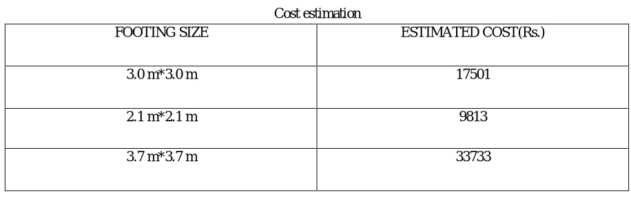
The estimated cost of various footings placed at various depths are as follows,
Table VIII Cost estimation
FOOTING SIZE ESTIMATED COST(Rs.)
3.0 m*3.0 m 17501
2.1 m*2.1 m 9813
3.7 m*3.7 m 33733
V. CONCLUSION
[image:5.612.76.534.487.630.2]REFERENCES
[1] Varghese P.C,2011,“LIMIT STATE DESIGN OF REINFORCED CONCRETE”, Prentice Hall of India Pvt. Ltd.,New Delhi.
[2] IS 6403-1981,” INDIAN STANDARD CODE OF PRACTICE FOR DETERMINATION OF BEARING CAPACITY OF SHALLOW FOUNDATIONS”, New Delhi.
[3] UmeshN.Waghmare and Dr.K.A.Patil, “INVESTIGATION OF SOIL AND BEARING CAPACITY IN DIFFERENT SITE CONDITIONS”, IOSR Journal Of Mechanical and Civil Engineering, Volume 3, 2012.
[4] Junhwan Lee and Rodrigo Salgado, 2001,”ESTIMATION OF FOOTING SETTLEMENT IN SAND”, The International Journal Of Geomechanics, Volume 2, Number 1,2002
[5] IS 6403-1981,” INDIAN STANDARD CODE OF PRACTICE FOR DETERMINATION OF BEARING CAPACITY OF SHALLOW FOUNDATIONS”, New Delhi.
[6] IS: 456 – 2000, “PLAIN AND REINFORCED CONCRETE”, New Delhi.