Predicting the Blast Pressure on Explosive
Forming Process by Experimentation and Finite
Element Analysis
N.Madan Mohan Reddy
#1K.Srinivasa Chalapati
#2L.Srinivas Naik
#3Assistant Professor Associate Professor Associate Professor Anurag Group of Institutions (CVSR College of Engineering) Hyderabad
ABSTRACT: Explosive forming is a process of forming a metal into a desired shape. In this technique an explosive charge is used instead of a punch or press. Blasts will take place by a low pressure explosive above the work piece. As a result the work piece deforms into the required shape. In this project the deformation characteristics of the part to be formed under blast pressure. When an explosive pressure is applied inside the Vacuum chamber of experimental setup the deformation of the G.I. Sheet with respect to the blast pressure is measured. The work piece used in this project is a G.I. Sheet. It is placed in between two circular dies. When the TNT (fire cracker) explodes, due to the exerted pressure the G.I. Sheet tends to move downwards and hence a hemispherical bowl is formed. Another rectangular shaped die is fabricated and the work piece is kept in between these two rectangular dies and the process is repeated. Hence a rectangular tray is obtained. The process parameters are recorded.
After the required shape is acquired, FEA (Finite Element Analysis) is done on the work piece. The deformation results of both experimental and FEA are correlated and pressure impended on the work sheet is predicted.
1. INTRODUCTION:
Explosive forming is a process of forming any metal into a desired shape by the use of blast pressure. An explosive charge is used instead of a press or punch. This explosive charge is made to explode and due to the exerted pressure and heat liberated, there will be a deformation on the metal work piece as per the shape of the die.An explosive can be defined as storage for energy which can be made to release with enormous pressure in such a manner that it can perform some kind of work.
2. LITERATURE SURVEY:
D. E. Stzohecker, R. J. Carlson, S. W. Porembka, Jr.,
www.ijraset.com
Vol. 2 Issue I, January 2014
ISSN: 2321-9653
I N TER NA T I ON A L J OU R N A L F OR R E S EA R C H IN A P PL I ED S C I ENC E
AN D E N G IN EE RI N G T E C HN OL O GY (I J R A S ET)
most effective manufacturing method of such parts.Non-Die Explosive Forming of Spherical Containers, Journal of Pressure Vessels, The advantages of good forming results, high dimensional accuracy and simplicity of the process and thus may be used as a new forming method for the spherical parts.
3.DESIGN AND FABRICATION OF EXPERIMENTATION:
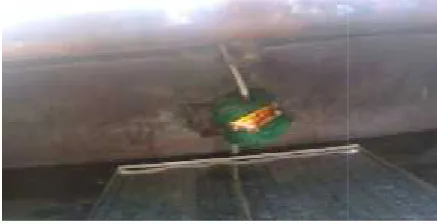
3.1 Experimental Setup Design: Experimental setup of the project consists of a base of 60cm length, 35 cm height and 1cm thick. Above the base a rectangular hallow box which is fully compact without any air gaps is fabricated and mounted. Stands of the base consist of a clamp which is mutual with the rectangular box in clamping. Both are together clamped by using a nut and bolt system to hold them very tightly. All the experimental setup is made of mild steel which is very hard and strong so that it could withstand the blast pressure. Low pressure explosives are used to get the formation of a bowl and a box. Below figure tells us about the experimental setup.
3.2 G.I. Sheets:
Galvanized sheet metal is a mild (carbon) steel that is used for a ton of different things. This material is tough and strong, and it can be fairly easily worked (bent or formed) in a number of different ways to produce useful products. It lasts a long time, too, because the zinc coating (the galvanizing) inhibits corrosion quite well.G. I. Sheets are available from the thickness of 0.3mm.
Fig.2 Fabrication of base stand
Fig.3 Fabrication of box and clamping
Fig.4Fabrication of Die’s
3.3 EXPERIMENTATION:
Mounting of the box on the stand and inserting the die’s and
work piece and clamping it inside the box. Before inserting
the work piece at its position between the die’s a mesh is
drawn for finding out the deflection.
Fig.5 drawing a mesh
Fig.7 positioning the explosive Fig. 8 provision for lighting the explosive
Fig.9 Circular deformation
Fig.10 Square deformation
Type of formed work piece No of node s on mes h Deflection values for 5 nodes taken by Vernier depth gauge y=N1+N2+N3 +N4+N5 (mm) Experi mental value of Averag e deflecti on y(mm)
Circular 226 N1=17.12 N2=17.23 N3=17.21 N4=17.14 N5=17.1 17.16 Square 316 N1=26.25 N2=26.31 N3=26.38 N4=26.32 N5=26.34 26.32
Table 1 Experimental Values Circular Vs Rectangular Plate
4. FINITE ELEMENT ANALYSIS:
Finite element analysis (FEA) has become commonplace in recent years, and is now the basis of a multibillion dollar per year industry. Numerical solutions to even very complicated stress problems can now be obtained routinely using FEA; I have done analysis on ANSYS Work bench 14.0 the results are shown graphically as follows.
[image:4.595.41.260.135.247.2]4.1 Analysis on Circular plate:
Fig. 11 Maximum Deflection isometric view
Nodes
(N)
Fig.7 positioning the explosive Fig. 8
[image:4.595.38.256.278.720.2]provision for lighting the explosive
Fig.9 Circular deformation
Fig.10 Square deformation
Type of formed work piece No of node s on mes h Deflection values for 5 nodes taken by Vernier depth gauge y=N1+N2+N3 +N4+N5 (mm) Experi mental value of Averag e deflecti on y(mm)
Circular 226 N1=17.12 N2=17.23 N3=17.21 N4=17.14 N5=17.1 17.16 Square 316 N1=26.25 N2=26.31 N3=26.38 N4=26.32 N5=26.34 26.32
Table 1 Experimental Values Circular Vs Rectangular Plate
4. FINITE ELEMENT ANALYSIS:
Finite element analysis (FEA) has become commonplace in recent years, and is now the basis of a multibillion dollar per year industry. Numerical solutions to even very complicated stress problems can now be obtained routinely using FEA; I have done analysis on ANSYS Work bench 14.0 the results are shown graphically as follows.
[image:4.595.306.551.516.651.2]4.1 Analysis on Circular plate:
Fig. 11 Maximum Deflection isometric view
Nodes
(N)
Fig.7 positioning the explosive Fig. 8
provision for lighting the explosive
Fig.9 Circular deformation
Fig.10 Square deformation
Type of formed work piece No of node s on mes h Deflection values for 5 nodes taken by Vernier depth gauge y=N1+N2+N3 +N4+N5 (mm) Experi mental value of Averag e deflecti on y(mm)
Circular 226 N1=17.12 N2=17.23 N3=17.21 N4=17.14 N5=17.1 17.16 Square 316 N1=26.25 N2=26.31 N3=26.38 N4=26.32 N5=26.34 26.32
Table 1 Experimental Values Circular Vs Rectangular Plate
4. FINITE ELEMENT ANALYSIS:
Finite element analysis (FEA) has become commonplace in recent years, and is now the basis of a multibillion dollar per year industry. Numerical solutions to even very complicated stress problems can now be obtained routinely using FEA; I have done analysis on ANSYS Work bench 14.0 the results are shown graphically as follows.
4.1 Analysis on Circular plate:
Fig. 11 Maximum Deflection isometric view
www.ijraset.com
Vol. 2 Issue I, January 2014
ISSN: 2321-9653
I N TER NA T I ON A L J OU R N A L F OR R E S EA R C H IN A P PL I ED S C I ENC E
AN D E N G IN EE RI N G T E C HN OL O GY (I J R A S ET)
Fig. 12 Maximum Deflection Front view
Fig.13 Maximum Deflection Top view
Fig. 14 Deflection Vs Time Curve
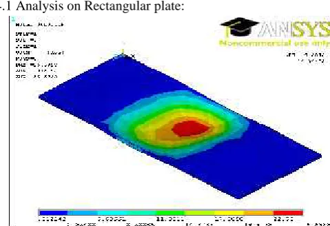
[image:5.595.50.550.85.596.2]4.1 Analysis on Rectangular plate:
Fig. 15 Maximum Deflection isometric view
[image:5.595.44.284.448.612.2]Fig. 17 Deflection Vs Time Curve
5 RESULTS & DISCUSSION:
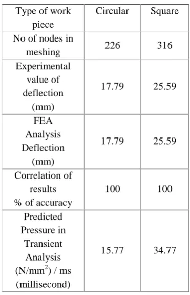
Table 2. Comparison of pressure between circular Vs Rectangular Plate
After Experimental calculations are recorded the obtained deflections values taken from 226 nodes for circular plate and 316 nodes from rectangular plate. By those values a finite transient analysis is done with the correlation of the deflection values. Finally the predicted pressure values per one millisecond have been furnished in Table 2.
REFERENCES
[1] D. E. Stzohecker, R. J. Carlson, S. W. Porembka, Jr., and F. W. Boulger
[2] He Fengman, Tong Zheng, Wang Ning, Hu Zhiyong
Type of work piece
Circular Square
No of nodes in
meshing 226 316 Experimental
value of deflection
(mm)
17.79 25.59
FEA Analysis Deflection
(mm)
17.79 25.59
Correlation of results % of accuracy
100 100
Predicted Pressure in
Transient Analysis (N/mm2) / ms (millisecond)
[image:6.595.33.219.359.647.2]