Technology (IJRASET)
Load Frequency and Voltage Control of
Autonomous Power System using Particle Swarm
Optimization tuned PID Controller
Gurjit Singh 1, Simarpreet Singh 2
1
M. Tech Student, 2Assistant Professor, Baba Banda Singh Bahadur Engineering College
Abstract— In this paper, Load Frequency Control and Automatic Voltage Regulation of a single area power system consisting of a non-reheat type thermal generating unit is presented. A power system is prone to instability due to sudden changes in load. The sudden change in load causes variation in frequency and voltage of the system. This can be a serious concern for the stable operation of the power system. The variation in frequency is dependent on the real power flow in the system and the variation in voltage is dependent on the reactive power flow in the system. The load frequency control and automatic voltage regulation is provided in every power system to counter act the variations in frequency and voltage. This paper presents the use of Proportional Integral Derivative Controller for improving the transient and steady state response of a single area power system. The PID controller offers simplest yet most efficient solution to many real world control problems. However, the tuning of the controller is a difficult process. Particle Swarm Optimization is an evolutionary computation technique which is mostly used for multi objective constrained optimization problems. It is used in this paper to search for the optimal gains of the PID controllers employed separately in the Load Frequency Control loop and the Automatic Voltage Regulation loop of a power system.
Keywords— Load Frequency Control; Automatic Voltage Regulation; Particle Swarm Optimization; PID controller; Integral Time Absolute Error; MATLAB Simulink.
I. INTRODUCTION
In a power system, the real and reactive power flows are never constant; they keep on varying due to the sudden changes in load. This sudden change of load causes variation in the frequency and voltage of the system which can be seen as a serious concern to stable operation of the power system. In order to prevent such variations in frequency and voltage, the power system is equipped with Automatic Generation Control (AGC) system which is composed of a Load Frequency Control (LFC) loop to counter act the frequency variations and an Automatic Voltage Regulation (AVR) loop to counter act the voltage variations [3]. The basic principle in controlling the frequency and voltage of the system is that variations in frequency are dependent on the real power flow in the system and the variations in voltage are dependent on the reactive power flow in the system. By controlling the real and reactive power flow in the system, the system frequency and voltage profile can be maintained [1], [2].
Many investigations on LFC and AVR of power system have been reported in the literature. There are inherent non-linearities present in the power system components and synchronous machines, therefore most of the controllers employed in LFC and AVR are primarily composed of an integral controller [2]. Proportional Integral Derivative (PID) controller is a powerful tool to improve both transient and steady state performance of a control system, but their tuning is a difficult process. Evolutionary computational techniques such as Particle Swarm Optimization (PSO), Genetic Algorithm (GA), Bacterial Foraging Algorithm (BFA), Simulated Annealing (SA), Ant Colony Optimization (ACO), etc. have been reported in literature to tune PID controllers. In this paper, PSO algorithm is presented for searching the optimal gains of PID controller in LFC and AVR of a single area power system comprising a non-reheat type thermal generating unit. The LFC and AVR loops are designed to operate around normal state with small variable excursions. The loops may therefore be modelled with linear, constant coefficient differential equations and represented with linear transfer functions [9].
Technology (IJRASET)
optimizer [4]. The first version of PSO could not handle non linear continuous optimization problems. Since then, many advancements in PSO were introduced and different variants of PSO algorithm were proposed [5] - [7]. The most standard one is the global best model of PSO introduced by Shi and Eberhart [8].
This paper is organised in six sections. The Section II describes the linearized model of LFC and AVR control loops based on which the simulation model was developed and analyzed, Section III describes the tuning of PID controller and implementation algorithm of PSO employed to improve the dynamic performance of the power system, Section IV presents the system considered in this study, Section V demonstrates the simulation results and comparison of PSO-PID controller based results with conventionally tuned PID controller and the conclusion of the work is derived in section VI, followed by the references.
II. LFC&AVRCONTROLLOOPSOFPOWERSYSTEM
A. Load Frequency Control
The LFC loop is assigned with maintaining the system frequency by controlling the real power flow in the system. Due to sudden
loading or unloading in the system, the generator observes a momentary speed change, which causes a small change in rotor angle δ.
This small change in rotor angle causes variation in real power and leads to the variation in system frequency.
Whenever a frequency change occurs, the LFC loop compares the new system frequency with the old system frequency and generates a command signal which is fed to the speed governor. The speed governor regulates the steam input to the turbine by some valve controlling mechanism and there by regulates the turbine mechanical output. This mechanical output when fed to the synchronous generator provides the regulated real power output.
B. Automatic Voltage Regulation
The AVR loop is assigned with maintaining the synchronous generator terminal voltage, which in turn maintains the bus voltage manipulating the reactive power output. This is achieved by controlling the excitation of the field winding of the synchronous generator.
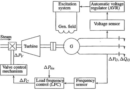
[image:3.612.176.438.431.621.2]The AVR loop continuously senses the terminal voltage; this voltage is rectified, smoothened and compared with a preset dc voltage reference. The compared result (i.e., error voltage) after amplification and shaping is used to control the synchronous generator’s field excitation. The schematic diagram of LFC & AVR loop is shown in fig. 1.
Fig. 1. LFC and AVR Control Loops of a Power System
Technology (IJRASET)
III. CONTROLSTRATEGYANDCONTROLLER
Most of the controllers employed in LFC and AVR are primarily composed of an integral controller. PID controller is employed separately in the LFC and AVR loop of the power system to improve its transient and steady state performance.
A. PID Controller
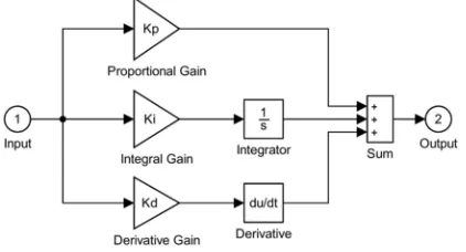
A Proportional-Integral-Derivative (PID) controller with its three term functionality covering treatment to both transient and steady state responses, offers the simplest yet most efficient solution to many real world control problems [10]. These controllers are easy to design, have low cost and are effective in most linear systems. The Simulink block diagram of standard PID controller is shown in fig. 2.
The corresponding transfer function of the block diagram is given by the following equation. Here, the KP, KI and KD are called
proportional gain, integral gain and derivative gain of the PID controller, respectively.
G(s) = KP + KI + KDs (1)
A properly tuned set of these gain values promises best controlling action and eliminate the use of complex controllers. There are many PID controller tuning procedures available in the literature. The conventional method of tuning requires finding the controller gains by trial and error [11].
The procedure of tuning the PID controller by trial and error is as follows:
Step 1: Set KD and KI to zero. By trial and error select KP that results in a stable oscillatory performance. In case of multi
input system, select KP that results near to critical damping.
Step 2: Vary KD with KP fixed so as to reduce the oscillations and result in reasonable overshoot and settling time.
Step 3: Till here the transients are taken care of. For the steady state performance vary KI with KP and KD fixed such that
[image:4.612.203.414.393.507.2]there is zero steady state error in minimum time. This completes the tuning of the controller.
Fig. 2. Simulink Block Diagram of PID Controller
B. PSO-PID Controller
The tuning of PID controller becomes more and more complicated for non linear systems, higher order and time delayed linear systems and systems that have no precise mathematical models. Particle Swarm Optimization technique is used here to search for the optimal controller gains of PID controllers employed in the LFC and AVR loops.
For the tuning of PID controller, the PSO algorithm generates a random population of the controller gains, then searches for the optimal set of gain values from this random population that minimizes the performance index/objective function. For the implementation of PSO tuned PID controller, Integral of Time Absolute Error (ITAE) is taken as the measure of performance index as it can be evaluated analytically in the frequency domain [12], [13]. The ITAE performance index is measured by
ITAE =∫ . | ( )|. (2)
Where, e(t) is the error signal and ‘t’ is the simulation time period. For the single area power system with LFC and AVR loops, the
Technology (IJRASET)
ITAE =∫ . |[∆ + ∆ ]|. (3)
The steps involved in implementation of PSO algorithm are:
Step 1: Initialize the particles to some linear positions in the range of KP, KI and KD.
Step 2: Set their velocities to zero.
Step 3: Evaluate the initial population by simulating the system model with each particle row value as the PID controller
value and calculate the performance index for each particle at their corresponding positions.
Step 4: Initialize local minimum (Pbest) for each particle.
Step 5: Find best particle (Gbest) in initial particle matrix based on minimum performance index.
Step 6: Start the iteration, iter =1.
Step 7: Update the velocity of the particle by using the equation:
Velocity = w*velocity+c1*r1*(Pbest-Particle)+c2*r2*((ones(n,1)*gbest)-particle)) (4)
Step 8: Create new particles from the updated velocity.
Step 9: If any of the new particles violate the search space limit, then choose the particle and generate new values within
the particle space.
Step 10: Evaluate the performance index value for each new particle at their corresponding position by simulating the
system model.
Step 11: Update Pbest and Gbest based on minimum value between new performance index and old performance index value.
Step 12: Update the Gbest global minimum value and its performance index.
Step 13: Iteration = iteration + 1.
Step 14: If iteration ≤ maximum iteration, go to step 7, otherwise continue.
Step 15: The obtained Gbest is the optimum set of parameters of the PSO-PID controller.
The PSO parameter values that provided a better solution and were used in the study are tabulated in Table I.
TABLEI
PSOPARAMETERSUSEDINTHESTUDY
Parameter Value
Population size 30
No. of iterations 30
Cognitive coefficient,
C1 2
Social coefficient, C2 2
Inertia Weight (w) wmax=0.9, wmin=0.4
IV. SIMULINKMODELOFSYSTEMINVESTIGATED
A power system consisting of a thermal generating unit of non-reheat type was considered for the simulation. The dynamic
performance of the system was observed in terms of frequency deviation, Δf and voltage deviation ΔV occurring due to an
Technology (IJRASET)
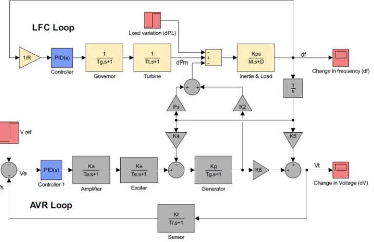
Fig. 3 Simulink model of LFC and AVR of a single area power system
For the Simulink model shown in fig. 3, the simulation time was set to 10 seconds. Typical simulation parameters for running the simulation model are tabulated in table II.
TABLEII
PARAMETERS USED IN THE SIMULATION MODEL
LFC Loop Parameters AVR Loop Parameters
Load change, ∆PL = 0.1p.u. Amplifier gain, KA = 10
Base power = 1000 MW Amplifier time constant, τA=
0.1 s
Governor time constant, τsg= 0.4 s Exciter gain, KE = 1
Turbine time constant, τt= 0.5 s Exciter time constant, τE= 0.4 s
Load damping constant, D = 1 Generator gain, KG = 0.8
Inertia constant, H = 10 MW/MVA Generator time constant, τG=
1.4 s
Speed regulation, R = 3 Hz/p.u.
Sensor gain, KR = 1
Sensor time constant, τR= 0.05
s
V. RESULTSANDDISCUSSION
The dynamic performance of the system was observed in terms of frequency deviation, Δf and voltage deviation, ΔV occurring due
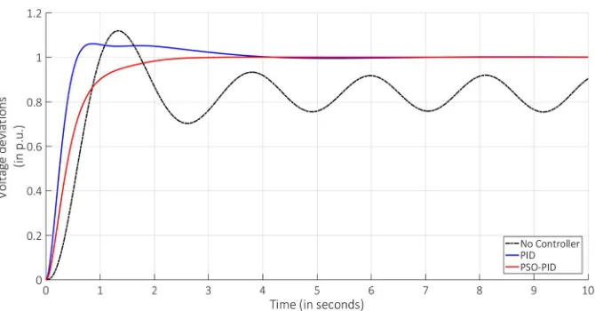
to an application of 0.1 p.u. step load perturbation to the system. The performance of the system is analysed in terms of dynamic response characterised by settling time and maximum overshoot of the response. The frequency response and the voltage response curves are shown in fig. 4 and fig. 5, respectively. A comparison of result obtained from the use of no controller, conventionally tuned PID controller and PSO tuned PID controller in the Simulink model is also provided in fig. 4 and fig. 5.
Technology (IJRASET)
TABLEIII
PIDCONTROLLERGAINSOBSERVEDFORTHESIMULINKMODEL
PID Controller Gains
LFC Loop AVR Loop
PSO-PID PID PSO-PID PID
KP 3.19 0.48 0.8 1.39
KI 2 0.01 0.38 0.95
[image:7.612.135.470.409.584.2]KD 2.39 3.31 0.3 0.48
Fig. 4. Frequency deviations of the system
Fig. 5. Voltage deviations of the system
The maximum overshoot and settling time observed for the frequency and voltage response curves are tabulated in Table IV.
TABLEIV
COMPARISONOFDYNAMICPERFORMANCE
Parameter PSO-PID PID
∆F Max. Deviation (Hz p.u.) 0.2989 0.3777
Settling time (sec) 4.559 9.585
Technology (IJRASET)
VI. CONCLUSION
Dynamic response of the system was observed for a 0.1 p.u. step load change. It is concluded that when the responses obtained from PSO tuned PID controller is compared with conventionally tuned PID controller, the overshoot in frequency is reduced by 20.8% and the settling time of voltage response is reduced by 53.7%. This shows that the PID controller tuned with PSO algorithm provides a fast and efficient control operation.
REFERENCES
[1] H. Saadat, Power System Analysis, 15th ed., New Delhi, India: Tata McGraw Hill Publication, 2002.
[2] D. P. Kothari and I. J. Nagrath, Power System Engineering, 10th ed., New Delhi, India: Tata McGraw Hill Publication, 2011. [3] Automatic Generation Control on Electric Power Systems, IEEE Std. Definitions of Terms, 1970.
[4] M. R. AlRashidi and M. E. El-Hawary, “A Survey of Particle Swarm Optimization Applications in Electric Power Systems,” IEEE Transactions on Evolutionary Computation, vol. 13, pp. 913-918, 2009.
[5] B. Gao, X. Ren and M. Xu, “An improved Particle Swarm Algorithm and its Application,” Springer: Procedia Engineering, vol. 15, pp. 2444-2448, 2011. [6] M. Imran, R. Hashim and A. N. E. Khalid, “An overview of Particle Swarm Optimization Variants,” Springer: Procedia Engineering, vol. 53, pp. 491-496,
2013.
[7] Z. H. Zhan, J. Zhang, Y. Li and H. S. H. H. Cung, “Adaptive Particle Swarm Optimization,” IEEE Transactions on Systems, Man and Cybernetics – Part B: Cybernetics, vol. 39, no. 6, pp. 1362-1381, 2009.
[8] Y. Shi and R. Eberhart, “A Modified Particle Swarm Optimizer,” IEEE, pp. 69-73, 1998.
[9] P. Kundur, Power System Stability and Control, 10th ed., New York: McGraw Hill Publication, 1994.
[10] K. H. Ang, G. Chong and Y. LI, “PID Control System Analysis, Design and Technology,” IEEE Transactions on Control Systems Technology, vol. 13, no. 4, pp. 559-576, 2005.
[11] M. Nagendra and M. S. Krishnarayalu, “AGC and AVR of Multi Area Power Systems with and without GRC Non Linearity,” International Journal of Advanced Research in Electrical, Electronics and Instrumentation Engineering, vol. 2, no. 6, pp. 2117-2126, 2013.
[12] Z. Lee Gaing, “A Particle Swarm Optimization Approach for Optimum Design of PID Controller in AVR,” IEEE Transactions on Energy Conservation, vol. 19, no. 2, pp. 384-391, 2004.
[13] J. F. Nirmal and D. J. Auxilia, “Adaptive PSO based Tuning of PID Controller for an Automatic Voltage Regulator System,” in Proc. International Conference on Circuits, Power and Computing Technology, 2013.
[14] A. Soundarrajan, S. Sumathi and C. Sundar, “Particle Swarm Optimization based LFC and AVR of Autonomous Power Generating System,” IAENG International Journal of Computer Science, vol. 31, no. 1, 2010.
ABOUTTHEAUTHORS
Gurjit Singh is pursuing M. Tech (Power System) from Baba Banda Singh Bahadur Engineering College, Fatehgarh Sahib. He obtained his B. Tech (Electrical Engineering) degree from RIMT Institute of Engineering and Technology, Mandi Gobindgarh, Punjab in 2012. His area of interest includes economic load dispatch, automatic generation control, optimization techniques and power system stability.