Technology (IJRASET)
Application of Global Maximum Power Point
Tracking (MPPT) in Solar PV Array
Mr. S.B. Parmar1, Mr B. S. Shah 2
1Lecturer in Electrical Engineering Department, G. P. Rajkot, Guj-India
2Lecturer in Electrical Engineering Department, L. E. College – Morbi, Guj-India
Abstract: This paper illustrates the Maximum Power Point Tracking (MPPT) of PV arrays, the efficiency of solar panels, and the change that occurs to the power output of a solar array under PSC.in this paper detail given about to Develop high efficiency MPPT approaches, suitable for Rapidly changing environmental conditions typical to tropical country like India, in order to increase efficiency during fluctuating conditions. To demonstrate the modified MPPT for partial shading. Partial shading effects the outputs from the panel and output of load will be affected due to implementation of system.so finally design and validation of a Maximum Power Point Tracking (MPPT) capable of tracking the true Global Maximum Power Point (GMPP) in the presence of other local maxima. This system tracks (MPP) exclusive of the use of expensive apparatus such as signal converters and microprocessors thus increasing the compression of the system.
Keywords: Maximum power point tracking (MPPT), algorithm, Photovoltaic I-V characteristics, Global Maximum Power Point (GMPP)
I. INTRODUCTION
As India is a stifling nation having high solar insolation, the best choice measure of renewable green energy is solar energy. India is the fifth largest creator and end user of electricity in the world and demand is expected to increase from 1300 billion kilowatt-hours (kWh) to 1,600 billion kWh by March 2018. India is in a state of recurrent energy lack with a demand-supply gap of almost 12% of the total energy demand. To fulfill this demand, Solar is the only exclusively renewable another energy source with the fundamental competence to satisfy the energy needs of India.To improve the conversion efficiency of the PV System, a practice is adopted which is known as Maximum power point tracking. MPPT make the PV system to operate at its maximum power. Many MPPT techniques have been introduced and implemented. By conservative popular MPPT methods, it’s easier to find the maximum power in nonlinear P-V curve under uniform insolation, as there will be single maxima.
though, under partially shaded conditions, these MPPTs can fail to track the real MPP owing to the multiple local maxima which can be appeared on P-V characteristic curve. On the impact of partial shading on PV panels and the disappointment of the conventional MPPT technique during partial shading, several research articles have been archived. So some have algorithm to find global maxima with the use of processors. This mission involves developing a compact MPPT DC-DC converter which uses local hesitant algorithm to obtain the local maximum power while ensuring that real global maximum power is always tracked with the help of global investigate algorithm.
II. SOLARPVARRAYUNDERPARTIALSHADINGCONDITION
Partial Shading is one of the major causes of power reduction in Solar Photovoltaic (SPV) Systems when we observe the characteristics of a Photovoltaic system. Under partial shaded conditions the non-linear Power-Voltage characteristics of SPV system gets more complex with multiple maxima.
A. Solar Pv Array Uniqueness and Its Non-Linearity Under Psc
Technology (IJRASET)
the P-V characteristic curve of PV array. conversely, due to the bypass diodes and the blocking diodes, abundant local maximum power points (multiple local maxima) can be existed under partially shaded condition
. Fig.1 Nonlinearity of Solar PV Array Characteristics under PSC
III. SYSTEMDESCRIPTIONANDMAXIMUMPOWERPOINTTRACKING
Maximum power point tracking is an essential part of a photovoltaic system. Photovoltaic systems have a distinct operating point that provides maximum power. An MPPT actively seeks this operating point. Maximum Power Point Tracking, normally known as MPPT, is an electronic arrangement that find the voltage (VMPP) or current (IMPP) routinely at which PV modules should operate to achieve the maximum power output (PMPP) under rapidly-changing environmental conditions. The penetration of PV systems as distributed power generation systems has been increased dramatically in the last years. In parallel with this, Maximum Power Point Tracking (MPPT) is becoming more and more important as the amount of energy produced by PV systems is increasing. Since the MPP depends on solar irradiation and cell temperature, it is never constant over time and hence Maximum Power Point Tracking (MPPT) technique should be used to track the maximum power point. Normally, PV module efforts well at cold temperatures and MPPT are operated to extract maximum power presented from them. When battery is totally discharged: MPPT can extract more current and charge the battery if the state of charge in the battery is lowers
A.IMPORTANCE OF MPPT FOR PHOTOVOLTAIC SYSTEMS AND SEPIC CONVERTER
Fig.2 block diagram of an MPPT system.
Technology (IJRASET)
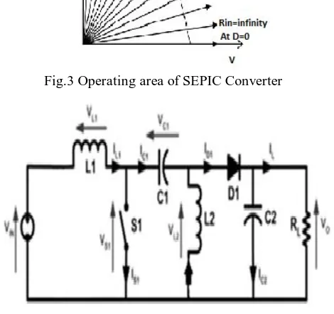
[image:4.612.232.381.262.385.2]capacitor to couple energy from the input to the output (and thus can respond more gracefully to a short-circuit output), and being capable of true shutdown: when the switch is turned off, its output drops to 0 V, following a fairly hefty transient dump of charge A number of MPP search techniques are planned and implemented in modern years. The SEPIC converter is used as an interface between the PV array and the load to offer load impedance matching with the PV source. SEPIC is essentially a boost converter followed by buck-boost converter. Therefore SEPIC is similar to buck-boost converter but it has the benefit of having non- inverted output. Also the coupling capacitor offers isolation between output side and input side which is unique to SEPIC converter only. In SEPIC converter, MPP tracking can be done with simplicity because of low input ripple current. In addition to that, SEPIC converter is more efficient than buck-boost converter. The circuit diagram of the SEPIC converter is shown below. The design of SEPIC converter has been explained and the designed values of the different parameters of the SEPIC converter are listed. The SEPIC converter is calculated for 1020 W load since four panels are connected in series as each panel is rated for 260 W peak power. Unlike uniform irradiation condition where unique MPP occurs at a voltage close to 0.85Voc, peak power points occur at lower, middle and higher voltage levels of the PV array.
Fig.3 Operating area of SEPIC Converter
Fig.4 SEPIC converter Circuit diagram
IV. FAILURESOFCONVENTIONALMPPTTECHNIQUES
[image:4.612.191.426.344.565.2]Technology (IJRASET)
Fig.5 PV characteristics showing MPP and operating points A and B
Fig.6 MPPT Failure in conventional method under PSC
V. PROPOSEDGLOBALMPPTALGORITHM
Usual MPPTs have been disastrous to track GMPP. Some enhanced MPP algorithms track with ADCs and microprocessor which is multifaceted. The solution described in this work finds the GMPP with reduced hardware complexity. For finding GMPP we have used two algorithms local dithering algorithm and Global search algorithm.The global MPPT methods implemented until now fail to reach the global MPP when global MPP occurs in between two local MPPs as shown in fig. Therefore, the planned algorithm has been developed such that it tracks global MPP.
Technology (IJRASET)
started now with starting duty cycle as D(k-1) with small step size in duty cycle, Δd. once the exact global MPP is reached, there will be a two step oscillation around the global MPP. Because the step size Δd is very tiny, the magnitude of oscillation around the global MPP is reduced so that the efficiency of the PV system is increased. According to this algorithm, global search is repeated every five minutes as weather conditions may have changed
Fig.7 Local and Global Dithering Algorithm
VI. SIMULATIONANDOBSERVEDMPPTRESULTS
Figures present a SIMULINK® diagram of boost converters. shows a SIMULINK® diagram of a Perturb and Observe maximum power point tracking Algorithm, while Figures 6.4 show a SIMULINK® of complete diagram of boost converters with P&O MPPT and PV module
Fig.8 Block diagram of a PV panel connected to the load.
Technology (IJRASET)
The models shown in the above figures were simulated using SIMULINK®. Simulation and results for boost converters have been recorded.
Fig.10 Output current, voltage and power of boost converter without P&O algorithm
Fig.10 Output current, voltage and power of boost converter with P&O algorithm
VII. CONCLUSION
In this paper an existing Boost Converter Simulation with trouble and Observe MPPT method is implemented in MATLAB-SIMULINK. The MPPT method simulated in this paper can recover the dynamic and steady state performance of the PV system at the same time. during simulation obersarvation is carried out that that the system completes the maximum power point tracking successfully despite of fluctuations. If external environment changes suddenly the system can track the maximum power point fast. The plots obtained in the different scopes have been shown in in fig 10. Here tiny loss of power from the solar panel to the boost converter output. This can credited to the switching losses and the losses in the inductor and capacitor of the boost converter which can be seen from the plots of the respective power curves. The algorithms described in be implemented for GMPPT to improve the performance of the simulated model.
REFERENCES
[1]M. G. Villella, J. R. Gazoli, and E. R. Filho, “Comprehensive approach to modelingand simulation of photovoltaic arrays,”IEEE Trans. on power Electron. vol. 24, no 5, May 2009.
[2]Ali Reza Reisi, MohammadHassanMoradi, ShahriarJamasb,“Classification and comparison of maximum power point tracking techniques for photovoltaic system: A review” Renewable and Sustainable Energy Reviews Vol 19 (2013) pp 433–44
Technology (IJRASET)
2007.[5]Hiren Patel and Vivek Agarwal, “Maximum Power Point Tracking Scheme for PV Systems Operating Under Partially Shaded Conditions”, IEEE Transactions on Industrial Electronics, Vol.55, No.4, pp 1689-1698, 2008
[6]Hiren Patel and Vivek Agarwal, “MATLAB- Based Modelling to Study the Effects of Partial Shading on PV Array Characteristics”, IEEE Transactions on Energy Conversions, Vol.23, No.1, pp 302-310, 2008
[7]R.Ramaprabha and Dr.B.L.Mathur, “MATLAB Based Modeling and Performance Study of Series Connected SPVA under Partial Shaded Conditions”, Journal of Sustainable development, Vol.2, No.3, pp. 85-94, 2009
[8]S. J. Chiang, K. T. Chang, and C. Y. Yen, “
[9]Residential photovoltaic energy storage system,”IEEE Trans. on Ind. Electron.,vol. 45, no. 3, pp. 385-394, June 1998R. Ramaprabha and B.L. Mathur, “Modelling and Simulation of Solar PV Array under Partial Shaded Conditions,” in Proceedings of IEEE International Conference on Sustainable Energy Technologies (ICSET 2008), Singapore, November 24-27, 2008
[10] S. J. Chiang, H.J. Shieh, and M.C. Chen, “Modelling and Control of PV Charger System with SEPIC Converter”, IEEE Trans. Ind. Electron, vol.56, no. 11, pp.4344-4353, Nov. 2009.
[11] N. Mohan, T. Undeland, and W. Robbins, Power Electronics: Converters, Applications and Design, 2nd ed., New York:Wiley, 11995, pp. 164–172.
[12] E. Koutroulis, ”A New Technique for Tracking the Global Maximum Power Point of PV Arrays Operating Under Partial-Shading Conditions”, IEEE journal of Photovolt, vol. 2, no. 2, april 2012.
[13] Global Maximum Power Point Tracking (Mppt) Technique In A Solar Photovoltaic Array Under Partially Shaded Condition Truptishree Dutta And Prof. Somnath Mait
[14] Bruendlinger R., Bletterie B, Milde M and Oldenkamp H, “Maximum power point tracking performance under partial shaded PV Array conditions”, proc.21st EUPVSEC, Dresden, Germany, pp.2157-2160, 2006.
[15] Kai Chen, Shulin Tian, Yuhua Cheng, and Libing Bai, “An Improved MPPT Controller for Photovoltaic System Under Partial Shading Condition,” IEEE Transactions on sustainable energy, Vol. 5, no. 3, pp.978-985. July 2014.
[16] Trishaw Esram, Patrick L. Chapman, “Comparison of Photovoltaic Array Maximum Power Point Tracking techniques”, IEEE Transactions on energy conversion , Vol 22, pp.439-449, June2007.