The Performance Characteristics of a
Surface-Modified Cutting Tool
Titus Bitek Watmon
A Thesis submitted in partial fulfilment of the
requirements of the University of East London for the
degree of Doctor of Philosophy
The Performance Characteristics of a
Surface-Modified Cutting Tool
Director of Studies: Dr David Xiao
Supervisor: Dr Vijitha M. Weerasinghe
School of Architecture, Computing & Engineering
Docklands Campus,
University of East London.
i
Abstract
In the past, many papers have been presented which show that the coating of cutting tools often yields decreased wear rates and reduced coefficients of friction. Although different theories are proposed, covering areas such as hardness theory, diffusion barrier theory, thermal barrier theory, and reduced friction theory, most have not dealt with the question of how and why the coating of tool substrates with hard materials such as Titanium Nitride (TiN), Titanium Carbide (TiC) and Aluminium Oxide (Al203) transforms the performance and life of cutting tools. This
ii
workpiece was consistently better for the EDMed inserts. The thesis discusses the relevance of the finite element method in the analysis of metal cutting processes, so that metal machinists can design, manufacture and deliver goods (tools) to the market quickly and on time without going through the hassle of trial and error approach for new products. Improvements in manufacturing technologies require better knowledge of modelling metal cutting processes. Technically the use of computational models has a great value in reducing or even eliminating the number of experiments traditionally used for tool design, process selection, machinability evaluation, and chip breakage investigations. In this work, much interest in theoretical and experimental investigations of metal machining were given special attention. Finite element analysis (FEA) was given priority in this study to predict tool wear and coating deformations during machining. Particular attention was devoted to the complicated mechanisms usually associated with metal cutting, such as interfacial friction; heat generated due to friction and severe strain in the cutting region, and high strain rates. It is therefore concluded that Roughened contact surface comprising of peaks and valleys coated with hard materials (TiN) provide wear-resisting properties as the coatings get entrapped in the valleys and help reduce friction at chip-tool interface. The contributions to knowledge:
a. Relates to a wear-resisting surface structure for application in contact surfaces and structures in metal cutting and forming tools with ability to give wear-resisting surface profile.
b. Provide technique for designing tool with roughened surface comprising of peaks and valleys covered in conformal coating with a material such as TiN, TiC etc which is wear-resisting structure with surface roughness profile compose of valleys which entrap residual coating material during wear thereby enabling the entrapped coating material to give improved wear resistance.
c. Provide knowledge for increased tool life through wear resistance, hardness and chemical stability at high temperatures because of reduced friction at the tool-chip and work-tool interfaces due to tool coating, which leads to reduced heat generation at the cutting zones.
iii
TABLE OF CONTENTS
Page
Abstract i
List of Figures x
Nomenclature xiv
List of Tables xvii
Acknowledgments xix
Dedication xxvi
Chapter 1
Introduction: 11.0 Metal Machining and Man 1
1.1.0 Motivation for this Study 2
1.1.2 Background to the Study 4
1.1.3 Objectives and Scope of the Study 5
1.1.4 Gap in Knowledge 6
1.1.5 Structure of the Thesis 7
1.1.6 Contribution to Knowledge 9
1.2.0:
Literature Review 101.2.1 Tool Wear 10
1.2.2 Crater and Flank Wear 11
1.2.3 Wear Equation 11
1.2.4 Tool Life Equation 12
1.2.5 Feedrates and other Factors that Influence Tool Wear 14
1.2.6 Laws of Friction 16
1.2.7 Machinability and composition of Steels Materials 16
1.2.8 Shear Zones 18
1.2.9 General Mechanics of Metal Removal 19
1.2.10 Geometry of Tool Bits and Holders 20
iv
1.3.0 Electrical Discharge Machining 22
1.3.1 Tribological Characteristics of EDM Process 22
1.3.2 State of the Art Modified Tool and its Applications 24
1.3.3 Uses of EDM 24
1.3.4 Advantages of EDM 25
1.4.0 Titanium 25
1.4.1 Titanium Coatings on Cemented Carbides and Cermets 25
1.4.2 TiN Physical Properties 26
1.4.3 TiN and HSS Mechanical Properties 26
1.4.4 TiN Chemical Stability 27
1.4.5 Benefits of TiN Tool Coating 27
1.4.6 Increased Wear Resistance of the Composite Tool 28
1.4.7 Increased Production Rate 28
1.4.8 Improved Cutting Performance 28
1.5.0 Finite Element Analysis 28
1.5.1 Von Mises Yield Criterion 29
1.5.2 Yield Strength 29
Chapter 2:
Tool Modification Using Spark Erosion Process and Cutting TestProcedures 31
2.0 Introduction 31
2.1.0 Tool Modification Process by EDM 31
2.1.1 EDM Metal Removal Rate 32
2.1.2 Electrical Discharge Machined Surface Finish 33
2.2.0 Preparation for Surface Modification Process 34
2.2.1 Identification of Inserts 34
2.3.0 The Novel Surface Modification Process 35
2.3.1 Apparatus 36
2.4.0 Requirements for Surface Preparation for Coating 37
2.4.1 Benefits of TiN Coatings 37
2.5.0 Modified Tool Surface Finish 37
2.5.1 Definition 37
v
2.5.3 Test Concepts 38
2.6.0 The Research Concepts and Plans 39
2.6.1 Preparation of Workpiece Billet 40
2.6.2 Equipment Used for Cutting Tests 40
2.6.3 objectives of the Experiments 40
2.6.4 Experimental Plan & Cutting Parameters 40
2.6.5 Rationale and Choice for Parameters 41
2.6.6 Calculations of the Spindle Speeds 41
2.6.7 Machining Time 42
2.6.8 Experimental Procedure in Machining 42
2.7.0 Work Surface Measurements 43
2.7.1 Cutting Tests Results 43
2.8.0 Repeat Tests for the 350 m/min Cutting Speed and chipped tool 49
2.8.1 The Repeat Tests Results 49
2.9.0 Conclusion Remarks 51
Chapter 3
Analysis of Enhanced Wear Resistance of Tools with Undulating SurfaceStructures 52
3.0 Introduction 52
3.1.0 Properties of Cemented Carbide Tool Inserts 52
3.2.0 Factors that influence Tool wear 53
3.2.1 Properties of a Tool Material 54
3.2.2 Hardness Property 55
3.2.3 Material Toughness 55
3.2.4 Wear Resistivity Property 55
3.2.5 Tool Wear Process 55
3.3.0 Experimental Details on CNC 56
3.3.1 Cutting Process Information 57
3.3.2 CNC Machining 57
3.3.3 G-Codes and Modular Program 57
3.3.4 Comparative Cutting Tests 58
3.3.5 Test Experiments 58
vi
3.4.0 Coated and Un-coated Inserts 59
3.5.0 Power Requirement 59
3.6.0 Expressions for Surface Roughness in Turning 60
3.7.0 Tool Numbering Function for CNC Turning Lathe 61
3.8.0 Novelty of the Crater-like Topography 62
3.8.1 Results Collected 62
3.9.0 Observed Outcomes of Chip Rubbing on tool rake face 63
3.9.1 Primary Wear Mechanism 64
3.9.2 Progressive Wear 65
3.9.3 Development of Crater Wear 65
3.9.4 Development of Flank Wear 66
3.9.5 Chipping of Tool Cutting Tip 66
3.10 Effect of Material Chemical Properties on Surface Finish 66
3.10.1 Work Surface Finish Readings 67
3.11 Effect of Speed on Built Up-Edge Formation 67
3.11.1 Effects of Undulating Surface on Tool Performance 68
3.11.2 Behaviour Patterns and Mechanism 69
Chapter 4:
Field Tests and Tool Performance Characteristics72
4.0 Introduction 72
4.1.0 Field Test Number I: Production of Fuel Nozzle Ring for Armoured Vehicle 72
4.1.1 Aims: 72
4.2.0 Equipment / Apparatus Used 72
4.2.1 Work and Tool Materials 73
4.3.0 Cutting Test Procedure 73
4.3.1 Machining Process Parameters 75
4.4.0 Observed Results and the Tool Performance 75
4.4.1 Components Made 77
4.4.2 Tool Analysis and Swarfs Produced 77
4.4.3 Presence of Temper Colours on the Chip 78
4.5.0 Field Test Number II: Production of Lift-Hub 78
4.5.1 Aims 78
vii
4.5.3 Work Material 79
4.5.4 Procedure 79
4.5.5 Drilling Parameters Used 79
4.6.0 Observed Tool Conditions and Performance 79
4.6.1 Swarfs Produced in Second Test and Chip Thickness 80
4.7.0 Components Produced at Field Tests 2 82
4.8.0 What is preventing Heat from damaging the cutting tips 82
4.9.0 Swarfs Generated and Their Characteristics 83
4.9.1 Power Load, Energy Consumption and Saving 83
4.10 Remarks on Cutting Conditions Optimisation 83
4.11.0 Summary 84
Chapter 5:
Simulation Modelling of the Turning Processes 865.0 Introduction 86
5.1.0 Development of Analytical Machining Models 87
5.1.1 Ernst and Merchant Model 88
5.1.2 Shear Angle Determination 88
5.1.3 Shear Angle Slip-Line Theory 90
5.2.0 Assumption of Forces Acting on a Cutting Tool 90
5.3.0 Finite Element Method 92
5.3.1 Simulation Modelling Set-up 92
5.3.2 AdvantEdgeTM FEM Components 93
5.3.3 Modelling Formulations 93
5.3.4 Simulation Modelling System 94
5.3.5 Steady State Metal Cutting Models 94
5.3.6 Specific Cutting Power 95
5.4.0 Oblique Model in Perspective 95
5.5.0 Coefficient of Coulomb Friction 96
5.5.1 Coulomb Friction Coefficient in this Study 98
viii
5.6.0 Aspects of Heat Generation in Metal Cutting 103
5.6.1 Zorev Model 103
5.6.2 Uniformly Distributed Load 103
5.6.3 Simulating the Model Systems 104
5.6.4 Linearly Increasing Load Assumption 106
5.7.0 Observed Simulations Results 107
5.7.1 Output Result Discussions 107
5.7.2 Temperature 107
5.7.3 Von Mises Stress 107
5.7.4 Plastic Strain 108
5.7.5 Heat Rate 108
5.8.0 Summary of Findings in the Modelling 108
Chapter 6:
Discussion of Results, Postulations and Contributions to Knowledge 1106.0 Interest in Tool-Wear 110
6.1.0 Hard Coatings 111
6.1.1 Analysis 112
6.1.2 Wear on Rake Face 112
6.1.3 Flank Wear 114
6.1.4 Surface Finish 117
6.2.0 Scrutiny and Postulations 117
6.2.1 Cutting Tests for Both Uncoated EDMed and non-EDMed Inserts 117
6.2.2 Friction Force on the Chip–Tool Interface 117
6.2.3 Stress Distributions on tool rake face explained 120
6.3.0 Discussion of Results 120
6.3.1 Finite Element Simulations 120
6.4.0 TiN Coating 120
6.4.1 Benefits of Coated Tool Having Undulating Surface 121
6.4.2 Increased Production Rate 121
6.4.3 Reduced Power Reading 122
6.4.4 Load Carrying Capacity of the Surface 122
ix
6.5.2 Graph explained for 350 m/min cutting velocity 124
6.6.0 Statement Leading to Contributions to Knowledge 126
6.6.1 Contributions to Knowledge 126
6.6.2 Hypothesis 127
Chapter 7:
Conclusions and Recommendations 1287.0 Observations 128
7.1.0 Weaknesses of the Study 128
7.2.0 Conclusions 129
7.3.0 Suggestions for Further Work 131
References 132
Appendix Ia–Ic Cutting Tests Results Pictures 150
Appendix II G-Codes and Modal Program 153
Appendix III Log book data for CNC machining 155
Appendix IV Surface Texture Measurement 156
Appendix V Coating Hardness Comparison 157
Appendix VI Titanium Coating Capabilities 158
Appendix VII Materials Properties of the Workpiece, tool and Coating layers 159
Appendix VIII ISO standards 8503-4 160
Appendix IX Evidence of Components made at Field Tests 162
Appendix X Simulation Modelling 163
Appendix XI AdvantEdgeTM software Formula 165
Appendix XII PATENT Sales Promotional Data Sheet by Imperial Innovations Ltd 166
Appendix XIII Lists of Published Works 169
x
List of Figures and Illustrative Diagrams
Page
Figure 1.1 Rake Faces after a Cutting Test: 4
Figure 1.2 SEM image of an EDMed Surface showing matt surface with valleys
and peaks 8
Figure 1.3 Taylor’s Tool Life Plot on Log-Log Scale 13
Figure 1.4 Illustration of how Material ahead of the Tool is sheared 20
Figure 1.5 SEM image of EDMed tool surface 23
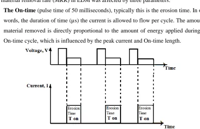
Figure 1.6 illustration of the Normal Distribution Chart for the “Operating Window” 24 Figure 2.1 Schematic Drawing of a Crater-like Surface Topography 32 Figure 2.2 Voltage and Current Characteristics for EDM machine (McGough, 1988) 32 Figure 2.3 A 3D SEM Profile of EDMed Tool surface discussed in section 1.3.1
as figure 1.2 about discussion on characteristics of EDM Process 34
Figure 2.4(a) Showing the Tool Design 35
Figure 2.4(b) Kennametal Inserts CNMA 432 K313X03 35
Figure 2.5 Micrograph showing a section through a surface-modified tool 36
Figure 2.6 Approach of the Electrode to the workpiece 36
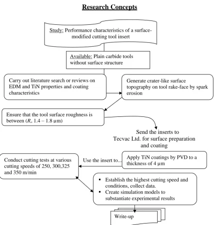
Figure 2.7 Design of Research Concepts 39
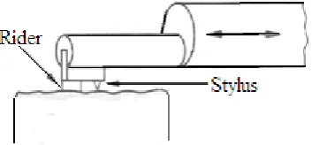
Figure 2.8 Measurement Techniques 43
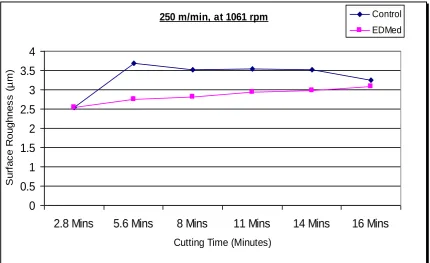
Figure 2.10 Results of cutting speed at 250 m/min 45
Figure 2.11 Results of cutting speed at 300 m/min 46
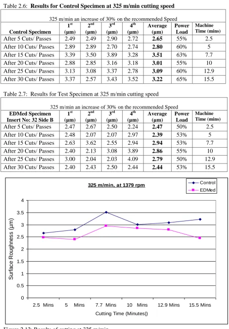
Figure 2.12 Results of cutting speed at 325 m/min 47
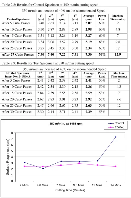
Figure 2.13 Results of cutting speed at 350 m/min 48
Figure 2.15 Microscopic Picture of chipping on control specimen 49
Figure 3.1 Division of Major Cutting Edge 55
Figure 3.2 Different Types of Tool wear growth during Metal Cutting 56 Figure 3.3 Carbide K313; CNMA-432, Uncoated EDMed Insert 59 Figure 3.4 Carbide K313, CNMA-432 EDMed Modified and TiN-Coated Insert 59 Figure 3.5 Feed marks etched on the work during machining operations 60 Figure 3.6 Typical tool function address for CNC lathes 61
xi
Figure 3.8 SEM image showing marks left by chips sliding over tool rake face 63
Figure 3.9 Types of wear on a single point cutting tool 64
Figure 3.10 Progress of Cratering 65
Figure 3.11 Progression of Flank Wear 66
Figure 3.12 SEM image of chipped insert 68
Figure 3.13 Effect of cutting speed on surface roughness 69 Figure 3.14 Workpiece surface roughness machined at 250 m/min 69 Figure 3.15 Workpiece surface roughness machined at 300 m/min 70 Figure 3.16 Workpiece surface roughness machined at 325 m/min 70 Figure 3.17 Workpiece surface roughness machined at 350 m/min 71 Figure 4.1 Directions of coolant application during the machining tests 73 Figure 4.2 Long Shiny Swarf Generated by EDMed Modified Tool 77 Figure 4.3 Swarf Generated by Control Inserts with Heat-Affected Discolouration. 78 Figure 4.4 Illustration of Orthogonal Metal Cutting Process 80 Figure 4.5 Showing long shiny Swarfs in a Tray in the machining centre compartment 81 Figure 4.6 Long shiny Swarfs produced by TiN coated surface modified Tool 81 Figure 4.7 Dark-bluish Swarfs produced by conventional tool at Newton Engineering 82 Figure 4.8 Suggested Procedures for tool selection and optimisation of cutting 84 Figure 5.0 Construction for Deriving Relation between Shear Angle (ϕ) and Cutting
Ratio 88
Figure 5.1 Nomograph for Shear Angle Readings 89
Figure 5.2 Lee and Shaffer’s Slip-Line Field Model 90
Figure 5.3 Model of Turning Process 91
Figure 5.4 Initial 3D Finite Element Mesh 92
Figure 5.5 AdvantEdgeTM Software Compositions 93
Figure 5.6 Showing a 2-D cutting model with a Zero Rake angle for Coulomb Friction 99 Figure 5.7 Model Mesh for tool with zero rake angle used for calculating µ 99
Figure 5.8 Free Body Diagram of Chip 101
Figure 5.9 Schematic Presentations of the Cutting Conditions 104 Figure 5.10 The Cutting Tool Initially Indents the Workpiece 104
Figure 5.11 The Chip Begins to Curl 105
Figure 5.12 Chip Curls Round and Hits the Workpiece. 105
xii
Figure 6.1 Illustration of the Development of Crater Wear 113
Figure 6.2 Illustrative Analysis of Diffusion Wear 114
Figure 6.3 Curves Representing Normal (σn) and Frictional Stress ( ƒ) Distribution on the
Rake Face 119
xiii
List of Tables
Page
Table 1.1 Physical Properties of TiN and HSS 26
Table 1.2 Mechanical properties of TiN and HSS at room temperature 27 Table 2.1 Experimental Plan and cutting Parameters used in the cutting test 41 Table 2.2 Results for Control Specimen at 250 m/min cutting speed 44 Table 2.3 Results for Test Specimen at 250 m/min cutting speed 44 Table 2.4 Results for Control Specimen at 300 m/min cutting speed 45 Table 2.5 Results for Test Specimen at 300 m/min cutting speed 45 Table 2.6 Results for Control Specimen at 325 m/min cutting speed 47 Table 2.7 Results for Test Specimen at 235 m/min cutting speed 47 Table 2.8 Results for Control Specimen at 350 m/min cutting speed 48 Table 2.9 Results for Test Specimen at 350 m/min cutting speed 48
Table 2.10 Comparative Results for Repeat Test I 49
Table 2.11 Comparative Results for Repeat Test I showing Flank 50
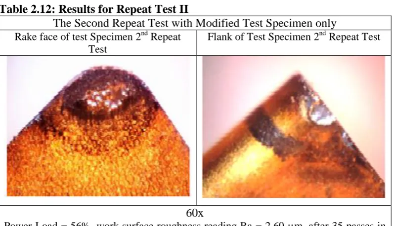
Table 2.12 Comparative Results for Repeat Test II 50
Table 3.1 Experimental Plan for CNC machining 58
Table 4.1 EDMed modified tool inserts used for rough turn 76 Table 4.2 EDMed modified tool inserts used for finish turn 76 Table 4.3 the company conventional tool inserts used for rough turn 76 Table 4.4 The Company’s conventional control specimens used fore finish Turn 77 Table 5.2 values of Coefficients of Friction used by researchers in past studies 98 Table 5.3 Lists of Coefficients of Friction from modelling with Zero Rake angle used in
calculating µ 100
xiv
Nomenclature
M B
ASME: 94.55 = Testing with single-point turning tools 1985
BS EN ISO3685 = Tool-life testing with single-point turning tools 1997 BS ENISO4288= Surface Profile including Texture
BS EN ISO4287= Surface structure Definitions
Al = Aluminium
3 2O
Al = Aluminium Oxide
= Angular Speed
R
A = Apparent Area
E = Applied Direct Current in electrical discharge machining
A = Area
S
A = area of shear plane
AA = Arithmetic Average (same as Ra)
W
A = Average Waviness
BUE = Built-up Edge
CLA = Centre Line Average (same as Ra) CVD = Chemical Vapour Deposition = Clearance Angle
01
G = CNC G-Code: Makes a linear feed move to a point 00
G = CNC G-Code: Presets a rapid motion command CAD = Computer Aided Design
CNC = Computer Numerical Control
C
l = Contact Length
U
C = Copper
C
= Cut-off length in surface measurementsC
F = Cutting Force
C
V = Cutting Velocity / Speed
C
d = Depth of Crater p
xv
eff
= Effective Stress
EDMed = Electrical Discharge Machined EDM = Electrical Discharge Machining
f
F = Feed Force
FEA = Finite Element Analysis FEM = Finite Element Method
f
= Friction Stress
HSM = High Speed Machining HSS = High Speed Steel tm = Machining Time
m
= Micrometre / Micron 3
EN = Mild Steel Grade Free Cutting
n
l = Natural Contact Length
n
F = normal force
PVD = Physical Vapour Deposition = Plus or Minus or Equal to
C
R = Radius of Curvature
= Rake Angle
a
R = Roughness Average
= Setting angleS
= shear stress
= Strain Rate0
= Strain Rate below which material properties are unaffected by strain ratet
F = Tangential Force
C
VT
n
= Taylor Tool Life Equation TiC = Titanium CarbideTiN = Titanium Nitride
xvi ALE = Arbitrary-Lagrangian Eulerian Ar = real area of contact
C = constant in Taylor tool life equation (Eq 2.3) C = The Capacitance
E = Young’s Modulus of elasticity f = feed in mm/rev
FC and NC = Force: along and perpendicular to the tool face,
Fc = cutting force component parallel to tool face Ff = feed force
Fp = cutting force component in power direction (i.e., parallel to V)
FP and FQ = Force: in the horizontal and vertical direction,
FR = cutting force component perpendicular to Fp and FQ
FS and NS = Force: along and perpendicular to the shear plane,
FS = cutting force component parallel to shear plane
Ft = Tangential force
Fw = total force (in uniformly distributed load)
G-Code = Computer Language of Preparatory Command in CNC programming I = Current (EDM Process)
KB = Crater width
KF = Crater Front distance KM = Crater centre distant KT = Crater Depth
M = the machining rate or volume removed per second in EDM, n = revolutions per minute –in machining processes
R = Charging Resistance in EDM process RԐ = Tool Nose Corner Radius
S = Mean spacing of adjacent local profile peaks SEM = Scanning Electron Microscopy
Sm = Mean spacing of profile peaks at the mean line
Ʈ = the friction shear stress which is dependent on the contact pressure t2/t1 = chip thickness ratio
xvii
Ti = Titanium
TiAlN = Titanium Aluminium Nitride TiC = Titanium Carbide
TiCl = Titanium Chloride TiN = Titanium Nitride
TiO2 = Titanium Oxide (Minerals Rutile)
Ton = Time on (EDM Process) tp = Bearing Ratio
V = cutting speed v = Poisson’s ratio VB = average flank wear
VBmax = maximum depth of flank wear
Vc = chip sliding speed Vd = the discharge voltage
W = Waviness
Wa = Waviness Average
Wc = Tungsten Carbide Tool
α = Rake angle
δ = linear deformation extent of secondary shear zone (Fig ) ε = true (ln) strain
έ
p= the effective plastic strain rate,
η = angle between tool face and plane of maximum shear stress (Fig. )
η
p = the inelastic heat fraction,θ = temperature
λ = chip compression ratio (reciprocal of cutting ratio = l/r) λc = cut off length in surface roughness measurements ρ = radius of curvature of tool tip
σ = flow stress
σ
eff = the effective stress,σn = the normal stress
σy = initial yield stress
xviii ϒ = shear strain
Φ = shear angle
xix
Acknowledgments
I have been fortunate to have worked with Dr David Xiao, my Director of Studies at the School of Architecture, Computing and Engineering (ACE) at the University of East London (UEL), and Dr Vijitha M. Weerasinghe, my second supervisor on whose ideas and concepts this project is based. Dr Weerasinghe also helped secure funding for consumables from Imperial Innovations Ltd. I thank these two special people very much from the bottom of my heart.
I also wish to acknowledge Imperial Innovations Ltd (part of Imperial College, University of London) for awarding over £8.5K towards this project for consumables during the experimental stage. I have also gained knowledge from some excellent technicians, both in industry and the world of academia, especially from the following: Steve Rauff in the Department of Product Design, John Shales, Laboratory Manager in the Department of Electronics Engineering, and Mrs Cyrile Wheeler, who helped me on many occasions with the design of conference posters; all these nice people are technicians in the laboratories of the School of ACE. This work involved the extensive use of both manual and CNC machine tools, and in particular I thank Nicholas I’Anson and his father Kenneth I’Anson, of Kennics Engineering, for granting me the use of their machine tools. I also wish to acknowledge Peter Kendle of Newton Equipment/Ajax Engineering in Barking, London, for his patience whenever I needed to use their Talysurf surface measuring machine. I wish to extend my gratitude to Steve Knoakes, an EDM technician at Newport Engineering, Harlow, Essex for his support in the machine setup. I also thank Nigel Atkinson of ANSYS Inc. for his help during the software evaluation exercise when I was considering using ANSYS for simulations and modelling for this work, and for his continued support and advice. I also received valuable feedback on drafts of portions of this thesis from my cousin Simon Auko, I am very grateful to him and other colleagues for correcting the many errors and inconsistencies in the manuscript, and am still responsible for all those that may still remain.
I am indebted to my cousin Santo Auma-Okumu, who helped my children Irene and MacBitek on many occasions with school matters while I was away working on this project in the UK. Taking these children to boarding school in Uganda and collecting them for holidays at the end of school term could not have been possible without his involvement and dedication.
xx
xxi
xxii
Declaration
I hereby declare that the data/ information recorded in this Thesis was
compiled by me for the award of Doctor of Philosophy Degree of the
University of East London. I did all Laboratory Experiments, data collection
and analysis of results. No part of this Thesis was directly copied from any
other work(s) done by somebody else other than citations, which have been
referenced. As such, no one has any claims over these materials. No part of
this Thesis should be copied for profit making without my expressed consent
or published without recognition of my effort.
1
Chapter 1
Introduction
Performance Characteristics of a Surface-Modified
Cutting Tool
This research focuses on the performance characteristics of a surface-modified carbide
cutting tool insert. After surface modification by electrical discharge machining (EDM) to
generate crater-like surface topography, the insert was coated with Titanium Nitride (TiN)
by physical vapour deposition (PVD) method. Comparative cutting tests were carried out
using conventional tools coated with TiN as control specimens, and the test specimens
were TiN-coated EDMed tools having crater-like surface topography.
1.0 Metal Machining and Man
2 attempt to achieve better metal cutting processes.
Dr. M. E. Merchant developed the first scientifically based model in 1945 of orthogonal metal cutting process. Merchant (1945) published paper offered a solution on how to reduce the shear plane angle, and he assumed that the shear flow stress in metal cutting was equal to that obtained from conventional tests. Oxley (1989), on the other hand, came up with a semi-empirical approach.
1.1.0 Motivation for this Work
This research sets out to explain why a TiN-coated metal cutting tool with undulating surface structure has an enhanced performance. Sue and Troue (1990) stated that TiN and TiAlN PVD coatings could reduce friction in tribological contact and increase abrasive wear resistance if the fusion between the substrates and the coatings are firm. Schulz et al. (2003) stated that ‘cutting edges of cemented carbide tools coated with TiC, TiN or (Ti, Al)N by chemical vapour deposition (CVD) and/or by physical vapour deposition (PVD) processes can show an increase of the service lifetime of tools by a factor of ten compared to uncoated tools’ for metal cutting.
The motivation for this work was a result of papers presented by many researchers, (Schulz et al., 2003; Dechjarern, 2002; Fouvry and Kapsa, 2001; Prengel et al., 2001; Jaspers et al., 1998; Bromark, Hedenqvist and Hogmarak, 1995) which explained that coating of cutting tools often yielded decreased wear rates and reduced coefficients of friction. Although different theories are proposed in the literature, covering areas such as hardness theory, diffusion barrier theory, thermal barrier theory, and reduced friction theory, most discussed the coating of plain tool substrates with hard materials such as TiN, Titanium Carbide (TiC) and Aluminium Oxide (Al203) and the coating’s ability to transform the performance of
cutting tools. This work looks into the coating of tool inserts with a crater-like (undulating) surface topography with TiN by a PVD process. The crater-like surfaces were created by the EDM method.
3
Aluminium Nitride (TiAl)N, to reduce the wear of engineering components in many tribological situations, have stimulated much research work (Arsecularanatne, Zhang and Montross, 2006; Schulz et al.,2003; Stoiber et al., 2002; Trent, 1991; Ezugwu, 2001). Stoiber et al. (2002) mentioned that today, ‘TiN coatings, according to their high hardness, corrosion and wear resistance, are widely used in industrial applications ranging from machining tools to decorative items’. The use of hard coatings has greatly improved the tribological performance of tool and machine elements. In fact, various hard coatings have been widely used to improve the performance and extend the life of cutting tools, dies and moulds (Holleck, 1986; Loffier, 1994). Among these hard coatings, TiN has been successfully used and extensively studied as a protective coating material (Kim. et al., 2003) because of its excellent properties; for instance its high melting point, high hardness and high thermal conductivity.
PVD hard coatings are well-known for providing surfaces with enhanced tribological properties in terms of friction and high wear resistance (Batista et al., 2002) by enhancing machining capability, increasing productivity and generating acceptable surface finishes with moderate power consumption during machining operations. ‘When properly applied, PVD coating can extend tool life by up to three times comparative to uncoated tools’ (Trent, 1991, cited in Ezugwu, 2001). However Ezugwu (2001) argues that in engineering applications, ‘it is necessary to use a sufficiently strong substrate and deposit a coherent, stress-free, defect-free and sufficiently thick TiN coating in order to increase the load bearing capacity, reduce substrate plastic deformation and suppress adhesive failure of the coating/substrate system’. Tool wear has been a recurrent problem in the metal machining industry and adversely affects the surface finish of the workpiece. A good surface finish has a great influence on the worth of products and satisfaction level of consumers. The causes of tool wear and surface defects that put complex limitations on tool life and the surface finish of products have been the subject of a large number of investigations
4
coating material such as Al203 or Titanium Chloride (TiCl3) which is readily available on the
market today.
1.1.2 Background to the Study
This project aims to further the work of a previous research programme that was based at Imperial College London (Dechjarern, 2002). Before this project started a ‘proof of concept’ experiments were done at UEL in 2006 which established that there is an operating windows of surface roughness which supports the modified surface structure theory. Figure 1.1 presents a graphical comparison of the rake faces of an EDM-coated tool and a plain-coated tool after 15 minutes of intermittent cutting.
Figure 1.1: Rake Faces After a Cutting Test: EDM-Modified Tool (left), Plain TiN-Coated Tool (right)
According to Dechjarern, ‘if the surface is smooth or too rough it would not work even if coated’. Dechjarern (2002) recommended surface roughness (Ra) values of between 1.4 – 1.8
micrometres as the operating window. This research proposes an extensive study by cutting tests experiments, field tests and computer simulation to substantiate the experimentally observed results on the ‘operating window’ hypothesis.
5
coating can protect a substrate material are the following, though not exclusively limited to these areas:
a) The wear resistance of the coating itself should be superior to that of the substrate. b) The coating lowers the friction coefficient and thereby the contact temperature. A
decrease in friction also reduces the propensity for severe adhesive wear.
c) The coating acts as a heat barrier owing to the lower thermal conductivity compared with that of the substrate. Thus, the proportion of frictional heat which dissipates into the substrate is reduced which, in turn, lowers the substrate temperature.
d) The coating has lubricating properties because it can generate secondary layers thereby reducing real contact area in the wear surface.
e) Elements of the coating material can diffuse into the substrate and thereby increase its wear resistance long after the original coating–substrate interface has been penetrated.
This work focuses on experimental work and the computer numerical simulation of the cutting process to gain a fundamental understanding of the wear characteristics and the mechanism of enhanced wear resistance of EDM modified surfaces under common cutting process loading conditions.
Tool life is the most important practical consideration in the selection of cutting tools and cutting conditions. Tools which wear out or fail slowly have comparatively long service lives, resulting in reduced production costs and more consistent dimensional and surface finish capabilities. That explains why tool life is the most common criterion used to rate cutting tool performance and the machinability of materials. This project will focus on tool performance higher speed of cutting.
1.1.3 Objectives and Scope of the Study
6
Hedenqvist et al, 1990). The present work investigated how much faster the tool is able to cut,
in addition to carrying out field tests that subjected the tool to real world operating conditions. A further aspect of the work developed a theoretical model that substantiated the experimentally observed results. This research investigated tool wear at the tool and work interface during orthogonal metal cutting. The specific objective of this study is to study the performance characteristics of a surface-modified cutting tool coated with titanium nitride and the inherent properties of the TiN coating substance,
1.1.4 Gap in Knowledge
Since the knowledge of tool coating first became known in the 1980s, tool engineers, materials scientists and other interested parties have been doing research on the benefits of tool coating technology. The gaps in knowledge that remain are:
i. Analysis of available criteria of tool life and tool wear assessment still indicates that the current methods of assessment are subjective and do not correlate with the tribology of metal cutting. They do not account for the cutting regime and thus do not reflect the real amount of the work material removed by the tool during the time over which the measured flank wear is achieved.
ii. The nature of tool wear is not yet clear enough in spite of numerous investigations carried out over the last fifty years. Although various theories have been introduced before to explain the wear mechanism, the complexity of the processes in the cutting zone hampers formulations of a sound theory of cutting tool wear. As a result, there is no universally agreed tool wear formula, which accounts for the work and tool materials.
iii. Knowledge on metal cutting tool life verses tool wear in relation to work material type is a phenomenon not yet well understood.
this is the area that motivated this study. This research will look into tool wear characteristics of Titanium Nitride (TiN) coated inserts having crater-like surface topography. The cutting speed will be much higher than ever tried before. The work materials will be mild steel grade EN-3 and stainless steel grade 314 and 316.
7
on the complex interrelationship that encompasses the thermal barrier function, and the relatively low sliding friction coefficient of TiN and mild steel. It is therefore, hypothesised that the TiN coatings (materials) will get entrapped in the valleys, and peaks, which may retain the coating longer thereby improving the resistance to wear.
However, it will not be possible to quantify the wear because there are still no universal wear equations due to the complexity of the wear process, which depends on the materials, contact conditions and environmental parameters in a number of different combinations.
1.1.5 Structure of the Thesis
Chapter 1, introduces the motivation and background that generated the enthusiasm to do this research, and introduces the concept of cutting tool modification and modern coating techniques with hard substances, which enhances the tribological properties in terms of the low friction, and high wear resistance of Titanium. Available literatures indicate that Titanium is the ninth most abundant element and the fourth most abundant metal in the earth’s crust (Kraft, 2003).
This chapter continues to provide a literature review of various scholars and researchers, which provided the background to this research. The analysis of information and data of published works provide the rationale for the experimental work in this project. It covers literature reviews on EDM processes and the tribology of rough surfaces in sliding friction. A detailed description of surface engineering such as surface treatment, coating by PVD, and surface modification are also discussed.
This chapter also looks at the comprehensive analysis of the effect of coated EDMed surface roughness on the contact point between the tool and the workpiece interface, including the properties and effects of TiN coating technology.
Chapter 2 discusses the tool preparation before coating the surface with TiN and the experimental approach that followed. A detailed study of EDM surface characteristics is described and the general procedures for the cutting tests and investigation into progressive tool wear.
8
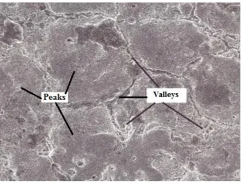
[image:32.595.116.470.246.515.2]requirements and attempts to understand the ways in which metal cutting tools fail. Broadly, tool failure may result from wear, plastic deformation, or fracture (chipping). Tool wear can be categorically classified by the area of the tool affected or by the physical mechanisms which produce it. The EDM process left a matt surface finish on the inserts, which was covered in small craters of a diameter-to-depth ratio of about 5 to 50 µm. The formation of these craters (valleys) is mainly a consequence of the discharge action. The degree of surface roughness depends on the size of the craters, as a result of energy per discharge during cutting.
Figure 1.2: SEM image of an EDMed surface showing matt surface with valleys and peaks
9
Chapter 5 begins with a literature review of current finite element modelling of metal cutting, and the general approaches that need to be understood in computer modelling and simulations. The effects of surface roughness on the cutting performance of TiN-coated tools is discussed, as well as how the numerical modelling of the cutting process will be carried out to investigate the effect of the crater-like surface topography on the performance of the tool. In-depth consideration of sliding friction conditions at the chip–tool and work–tool interfaces could possibly lead to a contribution to knowledge.
Chapter 6 discusses the final experimental and simulation results, which show that the EDMed TiN-coated tool inserts have properties that are resistive to wear during machining, and this phenomenon leads to a contribution to knowledge.
Chapter 7 summarises the research findings and gives detailed conclusions, with recommendations for the implementation and possible future work in the study of the performance of a surface-modified cutting tool.
1.1.6 Contribution to Knowledge
Tools used under the same conditions for different operations may have quite different usable lives, depending on a number of things, such as workpiece material, coolant used, feed rates selected, cutting speeds and critical tolerances or requirements. For that reason, the methods for predicting tool life are primarily only useful for comparative purposes. For example, when ranking expected levels of tool life for different work materials, tool materials, or cutting conditions, they cannot logically be expected to yield an accurate estimate of tool life for a given application unless prior application of data for similar parts are available. Based on these statements, this study contribution to knowledge orientates on the establishment of the fact that in the coating process the TiN particles fills up the valleys following the crater-like profile of the EDMed modified tools; thereby increasing the surface area of the coatings and as a result the TiN pockets in the valleys continue to provide wear resistance to friction. Thus, the summarised contributions to knowledge in this study;
a. relates to a wear-resisting surface structure for application in contact surfaces and structures in metal cutting and forming tools with ability to give wear-resisting surface profile.
10
c. provides technique for designing tool with roughened surface comprising of peaks and valleys covered in conformal coating with a material such as TiN, TiC etc which is a wear-resisting structure with surface roughness profile compose of valleys which entrap residual coating material during wear thereby enabling the entrapped coating material to give improved wear resistance.
Undulating surface topographies on cutting tips tend to hold coating materials longer in the valleys, thus giving enhanced protection to the tool and the tool can cut faster by 40% and last 60% longer than conventional tools on the markets today.
1.2.0 Literature Review
The overall background of this project including discussion on tool wear and the friction mechanisms of coated cutting tool are presented in the section below.
1.2.1 Tool Wear
Tool wear in machining is the gradual failure of cutting tools because of their usage, which involves loss of particles or material at the contact point between the tool and the workpiece. The contact between tool and workpiece generates heat, which culminates in the gradual failure of cutting tools after regular operation. Tool wear or failure is a term associated with tipped tools, tool bits, or drill bits that are used with machine tools, and is described by wear rate (volume loss per unit area per unit time). Tool wear is dependent on the temperature, cutting velocity and stresses due to friction generated at the tool–chip and tool–work contact interfaces. The rate at which cutting tools wear out depends on:
i. maximum temperature reached, ii. tool and workpiece materials, iii. tool shape,
iv. cutting fluids,
v. machine tool characteristics,
11 1.2.2 Crater and Flank Wear
There are two main types of tool wear during turning operations on a lathe; these are flank wear and crater wear.
a) flank wear is when a portion of the relief face erodes the already machined workpiece surface. Flank wear occurs on the relief face of the tool and the side relief angle and is generally attributed to the rubbing of the tool along the machined surface, thus causing adhesive and or abrasive wear, which in turn generates high temperatures. This affects tool-material properties as well as the work surface and tool life.
b) crater wear is where the contact between the tool and chips erodes the rake face. Crater wear can occur when the spindle speed is too low or if the feed rate is too high. In orthogonal cutting this type of wear typically occurs at locations where the tool temperature is the highest, and it occurs approximately at a height or distance equalling the depth of cut.
1.2.3 Wear Equation
The mechanics of wear is a very complex process to analyse because it depends on the material contact conditions and environmental parameters in a number of different combinations, thus it has not been possible to formulate a universally accepted equation for wear (Holmberg and Mathews, 2009). Holmberg and Mathews point out that many authors developed wear equations for different wear modes, but all of them are quite limited in their range of validity.
Archard (1953) both observed that ‘the worn out volume is directly proportional to the normal load and the distance of movement and is inversely proportional to the hardness of the material’. They the formulated and presented the wear relationship as
H s w K
V ' Equation 1.1
12
s
w
V
K
Equation 1.2Which is normally given with dimensions (10-6 mm3/Nm). It is not an ideal way of expressing wear but it has general support from researchers. There is clear physical argument for using the wear rate as defined above because it is the worn volume divided by the mechanical energy input into the contact energy (Holmberg and Mathews, 2009). The contact energy input can be described as the product of the normal load, the velocity and the applied time, which again is the same as the product of load and distance. Holmberg and Mathews (2009) continued by stating that this way of expressing wear should be taken into practice as widely as possible, to make it possible to compare and utilise wear data produced under different contact conditions.
1.2.4 Tool Life Equation
Tool life T is the cutting time at the end of which a given tool may be said to be unusable based on a selected tool failure criterion. A tool life equation is an empirical relationship between the tool life and one or more variables of the cutting process, such as cutting speed, feed rate and depth of cut. In 1907, Taylor published the following empirical formula for calculating cutting speed:
C
VT
n
Equation 1.3Where V is the cutting speed, T is the time (in minutes) that it takes to develop a certain flank wear-land and
n
is an exponent that depends on the tool and workpiece materials and cutting conditions, and is a constant. Note that C is the cutting speed at T = 1 (a one minute tool life). Thus, each combination of workpiece and tool material and each cutting condition has its ownn
and C values, both of which are determined experimentally. Cutting speed is the most significant process variables in tool life; however, depth of cut (d) and feed rate (f) are also important. The equation (1.3) can be written as shown in equation 1.4, and represented graphically in a log-log graph.Log V + n log T = log C Equation 1.4
13
Figure 1.3: Taylor’s Tool Life Plot on Log-Log Scale
On a log-log graph, therefore, the Taylor’s tool life equation represents a straight line, as shown in Figure 1.3, above which the exponents n, n1, n2… and constants C1 depend upon
tool and work materials, tool geometry and type of coolant used. The type of coolant is important as its correct usage is important in enhancing the performance of cutting tools.
Thus, Taylor equation (1.3) can be modified as follows:
Where d is the depth of cut and f is the feed rate (mm/rev) in a turning operation. The exponents x and y must be determined experimentally for each cutting condition. Taking n = 0.15, x = 0.15 and y = 0.6 as typical values encountered in practice, we see that cutting speed, feed rate, and depth of cut are of decreasing order of importance. Equation 1.4 above can be rewritten as
T = C1/n V-1/nd–x/n f-y/n Equation 1.7
Or T = C7V-7d-1f-4 Equation 1.8
For a constant tool life, the following observation can be made:
If the feed rate or depth of cut is increased, the cutting speed must be decreased, and vice versa,
Depending on the exponents, a reduction in speed can result in an increase in the volume of the material removed because of the increased feed rate and/or depth of cut.
14
1.2.5 Feedrates and other Factors that Influence Tool Wear
Many researchers on metal cutting look at metal cutting speed as the main factor that influences tool wear as well as tool life. Yet there are other parameters and characteristics of cutting processes, which are ignored because of contradicting results presented by different authors on the influence of cutting feed, depth of cut, and workpiece properties. However, the geometry of the cutting tool affects tool life as this geometry defines the magnitude and direction of the cutting force and its components.
When the machining process is carried out at high speed there is bound to be high contact temperatures at the tool–chip and tool–workpiece interfaces, which leads to softening of the tool material. The softening effects therefore promotes diffusion and chemical (oxidation) wear, and high contact pressures at these interfaces and the tool flank sliding over the freshly machined surfaces of the workpiece promotes abrasive and adhesion wear (Olson, Stridh and Söderberg, 1988; also cited by Astakhov, 2006).
Cutting tool wear is a product of differing physical, chemical, and thermo-mechanical occurrences. Various theories have already been introduced to explain the wear mechanism, but the complexity of the processes in the cutting zone hinders the formulation of a sound theory of cutting tool wear due to the mechanisms of wear, especially by adhesion, abrasion, diffusion and oxidation, which occur instantly. Thus, the identification of the dominant mechanism is far from simple, and most interpretations are subject to controversy (Schey, 1983).
15
proper wear characterization’, because they do not account for the tool geometry (the flank angle, rake angle, cutting edge angle, etc.) so they are not suitable for comparing the wear parameters of cutting tools with different geometries. Astakhov (2004) goes on to say
..…they do not account for the cutting regime (the cutting speed and feed(s)) and, thus, they do not reflect the real amount of the work material removed by the tool during the tool operating time, which is defined as the time needed to achieve the chosen tool life criterion (KT or VB).
Marinov (1996) introduced an approach formula to objectively evaluate tool wear and surface wear rate as radial wear per 1,000 sm2 of the machined area (S) as follows:
( ( ) ) ( ⁄ ) Equation 1.9 (Marinov, 1996) Where and are the initial radial wear and the initial length of the tool path, respectively, and l is the total length of the tool path. This equation proves that the surface wear rate is inversely proportional to the overall machined area, and it does not depend on the selected wear criterion (as cited in Astakhov, 1998).
The metal cutting process involves many different parameters, particularly cutting speed, cutting feed (feed rate), and depth of cut, and these parameters affect the tool life (Zorev, 1966). The uncut chip thickness or the cutting feed has a direct influence on the quality, productivity, and efficiency of machining. It is believed that the tool life decreases (and thus tool wear increases) with increasing cutting feed (Childs et al., 2000; Gorczyca, 1987; Zorev, 1966). This hypothesis comes from the generally adopted equation for tool life. For example, generalising the experimental data, Gorczyca (1987) proposed this equation:
If the cutting speed (v) and the depth of cut (dw) are both constant, then it follows from the above equation that tool life decreases when cutting feed (f) is increased.
16
experimental results can be explained by the fact that the cutting tests were carried out under variable cutting speeds, which resulted in different cutting temperatures (Astakhov,2006). In fact, the effect of cutting feed (the uncut chip thickness) on the surface wear rate (Astakhov, 2004) is of prime interest when maintaining the area of the machined surface constant (or the volume of the removed work material) in contrast to the length of the cutting path, because the area of the machined surface (or the volume of the removed work material) does not change with the cutting feed, while the length of the tool path does. This follows that if the cutting feed (f) is increased but the cutting speed (v) is kept constant, the given length of the tool path decreases, thereby the cutting time decreases as well as the corresponding tool wear.
1.2.6 Laws of Friction
In 1699, Amontons published his rediscovery of the laws of friction first put forward by Leonardo da Vinci. Though they were received with some misgivings, the laws were verified by Charles-Augustin de Coulomb in 1781.
The three laws of friction published by Amontons (taken from Shaw, 2005) state that:
i. The force of friction is directly proportional to the applied load (Amontons 1st Law)
ii. The force of friction is independent of the apparent area of contact (Amontons 2nd Law)
iii. Kinetic friction is independent of the sliding velocity (Coulomb’s Law).
These three laws only apply to dry friction, in which the addition of a lubricant significantly modifies the tribological properties. A tribological property of the cutting tool is also affected by cutting speed, as the speed increases during machining the tool life is rapidly reduced (Jacobson, Wallén and Hogmark, 1987). On the other hand, if cutting speeds are low, tool life is long, but the rate at which material is removed is also low.
1.2.7 Machinability and Composition of Steel Materials
17
of these metals also decrease machinability. Inclusions of oxides in steel may abrade the cutting tool, thus machineable steel should be free of oxides.
There are varieties of additives that can be added to steel to make the alloy easier to machine, these can be both metal and non-metal. Such additives may work by:
lubricating the tool–chip interface,
decreasing the shear strength of the material, or increasing the brittleness of the chip.
Sulphur (S) and lead (Pb) have been the most common additives, but bismuth (Bi) and tin (Sn) are increasingly popular for environmental reasons. Lead (Pb) acts as an internal lubricant in the cutting zone but has poor shear strength, thus it allows the chip to slide more freely past the cutting edge. When it is added in small quantities to steel, it can greatly improve machinability while not significantly affecting the steels strength. Sulphur (S) improves the machinability of steel by forming low shear strength inclusions in the cutting zone. These inclusions are stress risers that weaken the steel, allowing it to deform more easily. Mild steel EN-3 is easier to machine because of the addition of sulphur (0.6%) and phosphorus (0.06%). Kalpakjian and Schmidt (2002) stated that stainless steels have poor machinability compared to regular carbon steels because they are tougher, gummier and tend to work harden very rapidly. Kalpakjian continues to say that slightly hardening the steel may decrease its gumminess and make it easier to cut. On the other hand, aluminium (Al) is much softer than steel, and techniques to improve its machinability usually rely on making it more brittle. Aluminium alloy grades 2007, 2011 and 6020 have good machinability.
There are many factors affecting machinability, but there is no widely accepted way to quantify it. Instead, machinability is often assessed on a case-by-case basis, and tests are tailored to the needs of a specific manufacturing facility. Materials with good machinability require little power to cut, and can be cut quickly to obtain a good surface finish. Common metrics to measure machinability for comparison include:
i. tool life, ii. surface finish,
18 1.2.8 Shear Zones
The primary shear zone is a rather distinct narrow region in which the workpiece material is bent into the direction of the tool rake face, thus forming a chip (Burns and Davies, 1997). The friction at the tool-chip interface causes plastic deformation in the secondary shear zone, resulting in high temperatures. In the secondary shear zone high friction causes the chip to adhere to the rake face and hence it is called the sticking zone. It is in this zone that most of the deformation takes place. In the subsequent zone the chip will start to slide along the rake face until it leaves the tool, this part is the sliding zone. However, there are features of metal cutting which make the process complex. The complexity lies in the fact that:
i. The chip has an unconstrained free surface, thus the process geometry in cutting is not defined by the tool but merely depends on the workpiece material and the cutting conditions.
ii. The frictional conditions at the rake face form a complex system of interactions with the chip. The unconstrained chip geometry is highly influenced by the frictional conditions at the chip–tool interface. In turn the frictional conditions are dependent on the contact length between chip and tool and as a result of the chip geometry.
iii. The tool is in contact with new and fresh metal surfaces that are chemically highly active and lead to adhesion and diffusion reactions between chip and tool.
Following on from the above statement, there is evidence that there is a wide range of mechanical and chemical interactions taking place at the cutting zone. Understanding the basics of chip formation involves knowledge of several fields of engineering, including solid state physics, engineering mechanics and plasticity, material behaviour, tribology, basic concepts of chemistry and physics and thermodynamics and heat transfer (Shaw, 1984). Others, such as Lee and Shaffer (1951) as well as Palmer and Oxley (1989), based their analyses on a thick shear deformation zone, proposing ‘shear angle prediction’ models in accordance with the laws of plasticity.
The shear angle is defined as the angle between the direction of the cutting speed (V) and the shear plane. It is further assumed that the shear stress (τs) and the normal stress (σs) on the
19
2000). From the force equilibrium, the resultant force (F) is formed from the feed (Ff) and tangential (Ft) cutting forces, which means:
The feed force (or thrust force) is in the direction of the uncut chip thickness and the tangential cutting force (or power force) is in the direction of cutting velocity. The cutting forces acting on the tool will have equal amplitude but opposite directions with respect to the forces acting on the chip.
1.2.9 General Mechanics of Metal Removal
In orthogonal machining, cutting is assumed to be uniform along the cutting edge, therefore it is a two-dimensional plane strain deformation process. Hence, the cutting forces are only exerted in the directions of velocity and uncut chip thickness, which are called the tangential force (Ft) and feed force (Ff). However, in oblique cutting the cutting edge is orientated with an inclination angle (i), and the additional third force acts in the radial direction (Fr)
Referring to figure 1.4 it can be seen that as the edge of the tool penetrates the workpiece, the material ahead of the tool is sheared over the primary shear zone to form a chip. The sheared material/chip partially deforms and moves along the rake face of the tool, which is called the secondary deformation zone (Altinas, 2000).
The friction area, where the flank of the tool rubs the newly machined surface, is called the tertiary zone. The chip initially sticks to the rake face of the tool, which is called the sticking region. The friction stress is approximately equal to the yield shear stress of the material at the sticking zone, where the chip moves over a material stuck to the rake face of the tool. The chip stops sticking and starts sliding over the rake face with a constant sliding friction coefficient (Trent and Wright, 2000). The chip leaves the tool as it begins to lose contact with the rake face of the tool. The length of the contact zone depends on the cutting speed, tool geometry, and material properties.
20
Figure 1.4 Illustration of how Material ahead of the Tool is sheared
There are basically two types of assumption in the analysis of the primary shear zone. This led Merchant to develop an orthogonal cutting model by assuming the shear zone to be a thin plane.
1.2.10 Geometry of Tool Bits and Holders
The geometry of the tool tip plays an important role in tool wear. Single-point cutting tools are non-rotating cutting tools used in lathe machines, shapers and planers. The cutting edge is designed to suit a particular machining operation and may be shaped as needed. Tool holders when in operation hold single point cutting tools in the form of inserts rigidly. Klopstock (1926) was the first to show that the tool life and cutting forces could be favourably altered by restricting the contact length between the chip and tool.
a) Back and Side Rakes
The back rake helps control the direction of the chip, which naturally curves into the work due to the difference in length between the outer and inner parts of the cut. It also helps counteract the pressure against the tool from the work by pulling the tool into the work. Side rakes along with back rakes control the chip flow and partly counteract the resistance of the work to the movement of the cutter, and can be optimised to suit the particular material being cut. Brass for example requires a back and side rake of zero degrees, while aluminium uses a back rake of 35 degrees and a side rake of 15 degrees (Astakhov, 1998).
b) Nose Radius
21
work. The front clearance angle is usually 8 degrees, while the side clearance angle is 10 –15 degrees and partly depends on the expected rate of feed.
c) Tool Insert Materials
Cemented carbide, also called tungsten-carbide cobalt, is a hard material used in machining tough work materials such as carbon steel or stainless steel. Carbide tools can also withstand higher temperatures than standard HSS tools. Originally all tool bits were made of high carbon tool steels with appropriate hardening and tempering. 1.2.11 Uses of Coolant in Heat Removal
According to Timings (1998) the correct usage of cutting fluids is important in enhancing the performance of cutting tools. To obtain optimum rates of metal removal and maintain optimum tool service life, it is necessary to lubricate and cool the chip–tool interface zone. The following are factors likely to cause excessive heat during a metal cutting operation:
i. The cutting speed is too high,
ii. there is friction between the tool and workpiece,
iii. the tool is worn or is an incorrectly ground cutting tool,
iv. there is formation of a build-up edge on the cutting face of the tool.
In addition to cooling, cutting fluids aid the cutting process by lubricating the interface between the tool's cutting edge and the chip. Cutting fluids may be made from petroleum distillates, animal fats, plant oils, or other raw ingredients. Depending on which type of cutting fluid is being used, it may be referred to as coolant, cutting fluid, cutting oil, cutting compound, lubricant or compressed air (Timings, 1998). Every kind of machining (e.g. turning, boring, drilling, milling, broaching, grinding, sawing, shaping, reaming, tapping) can benefit from one kind of cutting fluid or another, depending on the workpiece material. Cast iron and brass are often machined dry. Interrupted cuts such as milling with carbide cutters are carried out dry due to damage to the cutters caused by thermal shock. Holmes (1971), in his paper “Factors affecting the selection of cutting fluids”, pointed out that the properties of a good cutting fluid are based on its ability to:
i. keep the workpiece at a stable temperature (critical when working to close tolerances). Very warm is okay, but extremely hot or alternating hot-and-cold should be avoided,
22
iii. ensure safety for the people handling it (toxicity, bacteria, fungi) and for the environment upon disposal,
iv. prevent rust on machine parts and cutters. 1.3.0 Electrical Discharge Machining
Electrical discharge machining (EDM) is one of the most important abrasion-less machining methods for ceramics and carbides. Since EDM does not involve any physical contact between the electrodes and workpiece it can be performed regardless of the hardness and strength of the workpiece materials. However, the thermal action of the EDM process is known to yield a relatively poor surface integrity, including craters, microcracks and unfavourable residual stresses, on the machined components. All EDM surfaces can be regarded as ‘possessing a Gaussian height distribution, with a surface skewness between ±1, and a kurtosis of about 2.5 – 3’ (Dechjarern, 2002). TiN-coated tungsten carbide and HSS tools are frequently used in metal cutting operations and increasingly replace uncoated inserts, drills and taps. It has been proven by other authors that coatings applied to tool inserts ‘considerably improve the tool life performance by suppressing the mechanisms of tool edge wear’ (Tecvac Ltd., 2012); Söderberg, Jacobson and Olsson, 1987 also cited in Wallén and Hogmark, 1989). Investigations into the TiN-coating of carbide and HSS tools are numerous. Most of the researchers have quantified the benefits of using ‘coated tools in terms of prolonged tool life’ (Thornley and Upton, 1987; Soliman, Abu-zeid and Merdan, 1987; Redford, El-Bialy and Mills, 1986; Walker, 1981; Ohishi et al., 1987).
1.3.1 Tribological Characteristics of EDM Process
23
temperature of the workpiece material. According to Fellers and Hunt (2001), ‘erosion rates are not affected by the material hardness but by the melting temperature of the material being machined’; thus the lower the melting temperature of the work material the faster the removal rate.
Figure 1.5 shows an SEM picture of a typical eroded surface obtained with current (I) = 1.5 ampere and Ton = 0.2 milliseconds. During each electrical discharge, intense heat is
generated, causing local melting or even evaporation of the workpiece material. With each discharge, a crater is formed on the workpiece. It can be seen that valley areas consist of a pool of molten metal, overlapping craters created by EDM and other features include peaks and deep cracking valleys. Aleksandrov and Barash