Active Air Suspension System
Suchit Naresh Moon
Department of Mechanical Engineering
Nagpur Institute of Technology, India
Abstract— Air ride suspension carries the load on each axle with a pressurized air bag just as a high pressure balloon. This system provides the smoothest and most shock free ride of any of the known vehicle suspension system. An air suspension includes a multiple air spring assemblies that each includes a piston airbag and a primary airbag mounted over the piston airbag. The primary and piston airbags each have a variable volume that is controlled independently of the other for active suspension control. Air ride system provides some important following features:
1) The system automatically adjusts air pressure in the air bag so that the trailer always rides at the same height, whether lightly loaded or heavily loaded.
2) The higher air bag pressure associated with higher trailer loads automatically provides a stiffer suspension which is required for a smooth ride.
3) The lower air bag pressure for lightly loaded conditions automatically provides for a softer suspension, thus providing the same ride quality for all trailer loading conditions.
Since each axle is independently supported by its own air bag, the air ride suspension is known as fully independent suspension system. The automatic control of the air bag pressure is accomplished by a solid state electronic control system specifically designed and packaged for vehicle use. This system continuously checks the ride height of the suspension and accordingly increases air pressure if the ride height is too low, by turning ‘ON’ an on-board air compressor. The air compressor stops automatically when the proper ride height is reached.
Key words: Air Suspension
I. INTRODUCTION
The job of a car suspension is to maximize the friction between the tires and the road surface, to provide steering stability with good handling and to ensure the comfort of the passengers.
If roads were perfectly flat, with no irregularities, suspensions wouldn't be necessary but they are not therefore these imperfections interact with the wheels of a car and apply some forces on them. A bump in the road causes the wheel to move up and down perpendicular to the road surface. The magnitude depends on whether the wheel is striking a giant bump or a tiny speck. Either way, the car wheel experiences a vertical acceleration as it passes over an imperfection.
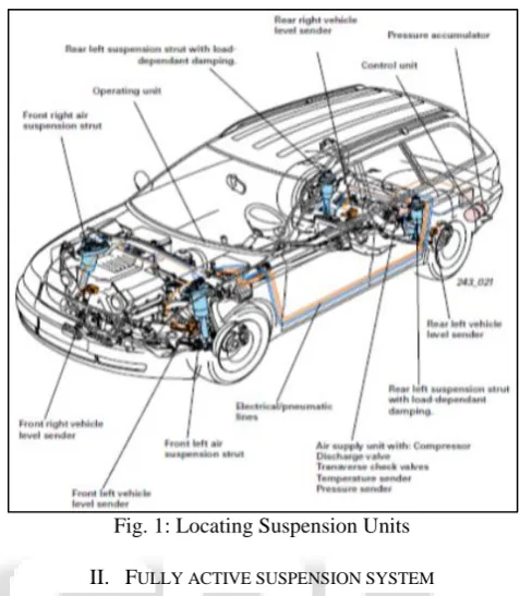
[image:1.595.308.547.123.397.2]Suspension consists of the system of springs, shock absorbers and linkages that connects a vehicle to its wheels. The suspension systems not only help in the proper functioning of the car's handling and braking, but also keep vehicle occupants comfortable and make your drive smooth and pleasant. It also protects the vehicle from wear and tear.
Fig. 1: Locating Suspension Units
II. FULLY ACTIVE SUSPENSION SYSTEM
Active suspension system has the ability to response to the vertical changes in the road input. The damper or spring is interceding by the force actuator. This force actuator has its own task which is to add or dissipate energy from the system.
[image:1.595.309.546.447.629.2]III. CLASSIFICATION OF ACTIVE AIR SUSPENSION
A. Hydraulic or Pneumatic Active Suspension
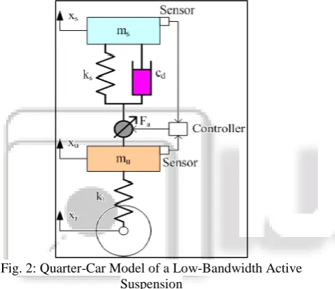
A hydraulic or pneumatic active suspension consists of a hydraulic or pneumatic actuator, a damper, and a mechanical spring. In general, the hydraulic or pneumatic active suspensions are suitable for low-bandwidth applications.
[image:2.595.47.287.67.181.2]Hence, the typical quarter-car model of the hydraulic or pneumatic active suspensions has been illustrated in Figure. 2
Fig. 2: Quarter-Car Model of a Low-Bandwidth Active Suspension
[image:2.595.319.540.68.217.2]In a hydraulic or pneumatic active suspension, the hydraulic or pneumatic cylinder works under motoring as a hydraulic or pneumatic actuator. Figure 3. Shows the block diagram of the electronic controller of the hydraulic or pneumatic active suspension. The vehicle engine or the electric motor drives a hydraulic or pneumatic pump to supply the hydraulic or pneumatic energy to the hydraulic or pneumatic actuator involved in the hydraulic active suspension, which creates oscillation-damping forces between the vehicular sprung mass and the vehicular unsprang mass. The hydraulic or pneumatic valve is driven by the low-power electromagnetic actuator, which is controlled by the control unit with the electric converter, in order to regulate the force of the hydraulic or pneumatic actuator.
Fig. 3: Block Diagram of Control for Hydraulic Active Suspension
B. Electromagnetic Active Suspensions
[image:2.595.56.301.279.490.2]In general, an electromagnetic active suspension is composed of an electromagnetic actuator and a mechanical damper. Both components work mechanically in parallel. The natural control flexibility of the electromagnetic actuator results in the important improvement in the suspension behavior, because the active suspension can produce the active control force to absorb road shocks rapidly, suppress the roll and pitch motions, and gives both safety and comfort.
Fig. 4: Electromagnetic Active Suspension
Furthermore, the other potential merit of the electromagnetic active suspensions is that the electromagnetic actuator can work under generating. This characteristic allows energy recovery from the suspension, when the actuator produces the damping force. Thus, the vehicular energy consumption decreases. The mechanism required to make this conversion results in considerable complications, which include backlash and increased mass of the moving part due to connecting transducers or gears that convert rotary motion to linear motion. It should be noted that these complications introduce an infinite inertia and therefore, a series suspension is preferable as shown in Figure 5.
Fig. 5: Block Diagram of Control for an Electromagnetic Active Suspension
The electromagnetic actuator is driven by the electric converter and controlled by the control unit based on the acquired signals and the control algorithms. The actuator power is supplied by the battery, which can be fed by the electric generator driven by the vehicular engine. Thus, the battery now replaces the complex and expensive hydraulic components. At the same time, the energy stored in the electromagnetic active suspension can be fed back to the battery via the electric converter if the electromagnetic actuator works under generating. The electromagnetic active suspension presented in includes a permanent-magnet linear actuator, a damper and a mechanical spring, which work mechanically in parallel.
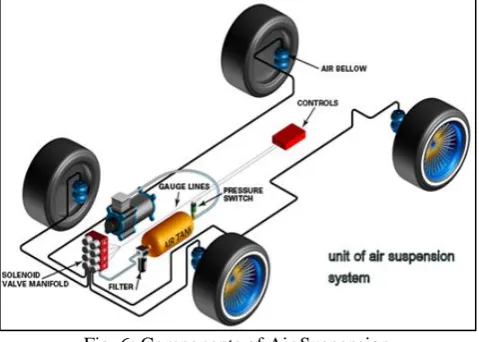
IV. BASIC COMPONENTS OF ACTIVE AIR SUSPENSIONS
An air suspension has three basic components. The air supply, the height control valves, the air bag sand the sensors. In the following section, we will discuss several different arrangements of these components.
A. Air Supply
The air supply is engine air compressor, the air tanks, air valves and air lines. The engine air compressor supplies air for every piece of air equipment on the vehicle. The maximum pressure supplied by the compressor varies. For many years, the air supply was maintained around 120 to 125 psi but on some newer, larger vehicles this has been increased to 135 psi. There will be dash gauges that will supply system pressure information but all vehicle shave what we refer to as a “pop off valve”. One can hear the valve “pop off” when the system reaches the maximum air pressure.
Fig. 6: Components of Air Suspension
The air supply is maintained through an arrangement
as 10 to 12 different tanks. The terminology for these tanks varies greatly also. There are primary tanks, secondary tanks, wet tanks, auxiliary tanks, front brake tanks, rear brake tanks. The only purpose of air tanks is to store air for the different systems on the vehicle.
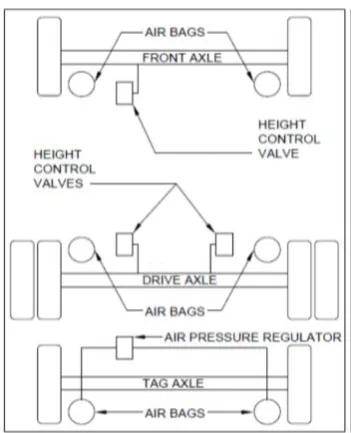
B. Height Control Valves
[image:3.595.308.542.216.410.2]The height control valves (HCV) are kind of the brains of the system. They dictate how much air is in the air bags. This dictates the height the vehicle sits at, therefore they are known as Height Control Valve. Most HCVs are mechanical valves but electronic HCVs are available. The HCV is mounted to the frame of the vehicle.
Fig. 7: Height Control Valve
C. Air Bags
[image:3.595.48.288.551.722.2]Fig. 8: Basic Diagram Showing Different Components of Active Air System
D. Sensors
[image:4.595.304.546.301.492.2]In active suspension systems, sensors are used to measure the accelerations of sprung mass and unstrung mass and the analog signals from the sensors are sent to a controller. The controller is designed to take necessary actions to improve the performance abilities already set. The controller amplifies the signals which are fed to the actuator to generate the required forces to form closed loop system (active suspension system) Figure 9.
Some types of sensors used in active suspension system are as follows:
Position sensor (LVDT position sensors) Height sensor
Air bags pressure sensor Bumps sensor
Fig. 9: Active Suspension System
V. LAYOUT & WORKING OF ACTIVE SUSPENSION SYSTEM
Active air suspension system consists of an air tank, 4-way air valve assembly (pressure solenoids), air compressors, the
necessary pressure sensors, all wiring and air fittings, and an in-car electronic control module. In order to understand the working of active air suspension system, we need to understand functions of each component. Using the diagram below, we can find an in car input of whether to raise or lower the car through the entire system. From the cabin of the vehicle, using the control module, an air pressure is selected for each corner. Once a pressure has been chosen, the signal travels to the computer, which sends the request to the pressure solenoids. The solenoids then either send air to the air springs to inflate them or bleed pressure from the air springs to deflate them. The air compressors are used to fill the air tank, which feeds air to the pressure solenoids. In order for the in-car control module to know the pressure in each air spring, pressure sensors are used in conjunction with the pressure solenoids. In other words, the in-car control module represents the gauge faces while the sensors are the gauges themselves. While the arrangement of components there is a need of attention to cutting the airlines straight and making sure to run the lines away from anything potentially harmful.
Fig. 10: Arrangement of Active Air Suspension System
VI. CONCLUSION
Active air suspension controls the vertical movement of the wheels with an on-board system and air bags both which provide more complex ability to the system. The normal coil spring is not used in this suspension, thus eliminating its vibration and improving riding comfort. The spring function has been replaced by the air bags but emergency springs are also used. The pressure control range has been widened to maintain a flat vehicle position even while turning. The sensors used are pressure sensors and height sensors.
REFERENCES
[1] Design and simulation automobile active suspension system by Mohd. Asqalani Bin Naharudin, University Malaysia Pahang, November 2008
[image:4.595.43.285.334.717.2][3] Pneumatic active suspension system for a one-wheel car modelusing fuzzy reasoning and a disturbance observer YOSHIMURA Toshio†, TAKAGI Atsushi (Department of Mechanical Engineering, Faculty of Engineering, The University of Tokushima, Minamijosanjima-cho 2-1, Tokushima 770-8506, Japan), July 5, 2004