2018 International Conference on Modeling, Simulation and Analysis (ICMSA 2018) ISBN: 978-1-60595-544-5
Modelling and Simulation of Dynamics of Screw-Locking Robot
Song-jun LU, Yi-hao LI, Lu-min CHEN
*, Cai-dong WANG and Xin-jie WANG
School of Electromechanical Science and Engineering, Zhengzhou University of Light Industry, Zhengzhou, Henan, China, 450002
*Corresponding author
Keywords: Screw-locking robot, Positioning error, Flexible screwdriver, Dynamic analysis.
Abstract. In the application of screw-locking robot based on machine vision technology, the axis of the screw for connecting the workpiece is difficult to accurately coincide with the axis of the screw hole on the workpiece due to the inevitable robot positioning error, which brings some difficulties about screw-locking process and reduces screw-locking efficiency and quality. In this paper, the dynamic behavior of screw-locking robot system is studied by using multi-body system dynamics method. Through modelling and simulation of ADAMS dynamics, the influences of the positioning error of screw relative to screw hole on the system dynamic performance are analyzed comparatively. The influences of flexible screwdriver on the system dynamic performance are studied. The simulation results show that flexible screwdriver can improve the self-adaptability of the axis eccentricity when the screw is locked into the screw-hole. The results studied in this paper can provide reference for optimization design of mechanical and control system of screw-locking.
Introduction
In recent years, with the demands of electronic products and communication equipments growing rapidly day by day, improving the assembly efficiency and assembly quality of electronic components is particularly important [1].
Currently, screw-locking robots have been improved greatly compared to the traditional screw-locking equipments, having been experienced from semi-automatic to fully automated development process. However, there are still some shortcomings to be improved, such as the effect caused by system positioning error in production condition, system internal and external vibration and performance of some system components. These factors will have some certain impacts on the system dynamic performance, thereby affecting automatic screw-locking efficiency and quality [2, 3], even leading to the failure of the screw-locking. Many scholars have done a lot of research on geometric analysis of screw assembly ability [4] and screw joint for precise assembly of miniature parts [5]. However, there are few studies on the effects of axis eccentricity due to the positioning error of screw relative to the screw hole and performance of electric screwdriver in dynamics.
In this paper, the influences of the screwdriver performance and the axial eccentricity of screw and the screw hole on the dynamic performance of screw-locking system are studied. Through simulation analysis, the corresponding results are obtained, and the corresponding improvement measures are put forward according to the analysis results.
Modelling and Simulation Analysis
Geometrical and Physical Model
stroke and other aspects. The object system in this paper has the requirements of high precision, high stiffness and so on. Taking into account a variety of factors above, rectangular coordinate robot that is simple to be controlled is put to use for automatic screw-locking system.
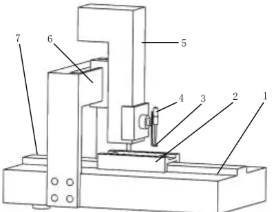
[image:2.595.195.396.116.270.2]1. Workbench 2. Workpiece holder 3. Screw locker 4. Electric screwdriver 5. Z-axis mobile platform 6. X-axis mobile platform 7. Y-axis mobile platform
Figure 1. Schematic diagram of automatic screw-locking robot.
Rectangular coordinate screw-locking robots have three freedoms of movement of X, Y and Z directions. The Y-axis drives the workpiece on the workbench to move independently in this direction. The X-axis mobile platform moves horizontally in the X-axis direction with driving the Z-axis mobile platform. The precise positioning of the screws is achieved by the precise cooperation of the X, Y and Z axis to ensure the tasks of screw-locking proceed smoothly. The screw automatic feeding module is a part of the automatic screw-locking system. In this paper, only one screw aimed is placed in the middle of the screw locker mechanism replacing the feeding part to simulate.
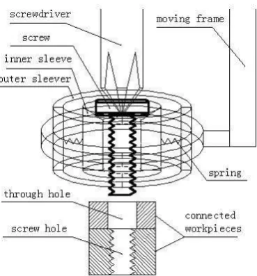
The existing screw lockers are mostly active control mechanisms that is making use of power devices, including electromagnetic and pneumatic control devices [6, 7] to control clamping and releasing of the screw jaws or clamping plates. Such devices are generally constructed in a complex manner with having higher production costs. Frequent clamping and releasing operations add difficulties to the control system. In this paper, the screw locker device is designed based on passive control characteristics. The springs are compressed when they are squeezed and restore to the original state when the squeeze force is canceled within the elastic limit. It is simple and easy to achieve with saving production costs. In this paper, the schematic diagram of screw locker device is shown in Fig. 2.
The screw locker in this paper is composed of a moving frame in the Z direction, four parts of the outer sleeve rounding into a circle, four parts of the inner sleeve rounding into a circle and four springs. The four parts of the outer sleeve are fixed on the Z-axis moving frame. The four parts of the outer sleeve and the three parts of the inner sleeve are respectively connected with four springs so as to make the screwdriver drive the screw passing the screw locker mechanism and complete the screw-locking process smoothly. When a screw-locking process is completed, the inner sleeve is restored to its original position under the action of the springs, waiting for the next screw-locking process. The cross head screwdriver and the cross head screw are brought into contact correspondingly by matching. Standard sizes of screw adopt GB/T822-2000[8]. It is 2.5mm from the bottom end of screw to the top of workpiece, namely, the initial height of the screw is 2.5mm.
1 2 3 4
5 6
Figure 2. Schematic diagram of screw locker device.
In this paper, the main parameters of screw are as follows: nominal diameter of 1mm, single thread, right hand, pitch of 0.25mm, nominal length of 3mm [9]. The upper part of the connected part with thickness of 1mm has a through-hole diameter of 1.1 mm. The lower part screwed into the workpiece with thread depth of 2mm has a thread nominal diameter of 1 mm. The screw is made of aluminum.
The Creation of Flexible Body
Considering the elastic deformation of some components, it is necessary to regard some components as flexible body [10]. The screwdriver is direct drive part of screw-locking, so the flexible performance of the screwdriver plays a very important role in the quality of screw-locking. Flexible body creation has a variety of methods. Because the shape of the screwdriver in this model is relatively simple, so the creation of screwdriver flexible body adopts geometric shape method of ADAMS / AutoFlex module. Different modal numbers have different effects on the deformation of the flexible screwdriver. In order to exert the performance of the flexible body better, the corresponding modal numbers that have positive effects on the deformation of the flexible screwdriver should be enabled and that have negative effects should be disabled. In the simulation of this situation, the flexible screwdriver has a total of 20 modal numbers. The disabled mode numbers are1, 5, 7, 8, 9, 10, 12 to 20 and the rest are the enabled modal numbers.
Contact Collision Model
Contact collision model divides the collision process into free movement and contact deformation. When the two components are in contact, the contact deformation and contact force between the components are regarded as continuous change from zero. It establishes the function of the force and contact deformation in the process of collision by taking into account the elasticity and damping of contact surface of collision body. The equivalent spring damping model [11] commonly used in ADAMS is as follow:
C
(
)
K
F
e
material properties are added to every part of the model, besides, corresponding constraint pairs and movement pairs are added according to the relative motion of various components of the model with adding the corresponding forces and torques. The contact forces between the screwdriver and the screw and between the screw and the screw hole are added to transmit force and torque respectively. The thrust force applied to the screwdriver is 0.1 N and the magnitude of the torque applied to the screwdriver is 8 N • mm. The contact stiffness coefficients K between the screw and the screwdriver, and between the screw and screw hole are both 20000. The damping factors C are both 10. The electric screwdriver falls from the static under the action of the force and the torque. Finally, simulation control is carried out. In this paper, the simulation time is set to 1s and the integration step is 0.1ms.
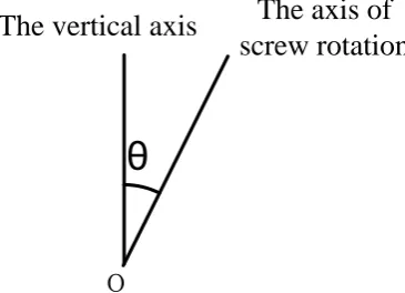
It is of great practical significance to study the movement postures of the screw in the process of screw-locking for real-time feedback control of the system. The movement postures of the screw are measured by Euler angle method. In this paper, the Euler angle measurement method uses the rotation order of Z-X-Z body axis. The nutation angle of the screw in the screw-locking process is measured because the angle of nutation that belongs to Euler angle of the screw is the most important factor affecting the posture of the screw in the process of screw-locking. The schematic diagram of nutation angle of screw is shown in Fig. 3.
o
The vertical axis
The axis of
screw rotation
[image:4.595.206.389.310.442.2]θ
Figure 3. Schematic diagram of nutation angle of screw.
In the actual condition, it is difficult to completely overlap for the axes of the screw and the screw hole due to the positioning error caused by various reasons. There will be different kinds of axis alignment errors, such as the displacement error, the angle error between the axis of screw and the axis of screw hole, or the combination of the first two kinds of errors.
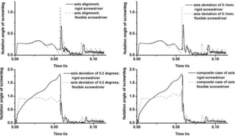
Figure 4. Comparison of angle of nutation of screw under different positioning conditions.
The maximum angle of nutation in the case of axis alignment is the smallest of the four cases when the screwdriver is rigid, which indicates that the ideal axis alignment is most favorable for the process of the screw-locking. The maximum Euler angle of screw with respect to the relative axis deviation of 0.1mm is smaller than both the relative axis deviation of 0.2 degrees and the composite case of axis deviation. It indicates that the relative axial deviation of angle has more influence than the deviation of the axial displacement on the screw posture in the screw-locking process. Besides, the simulation results of the relative axis deviation of 0.2 degrees and the composite case of axis deviation are very close. It further shows that the relative axis deviation of angle plays a primary role in the screw-locking process.
When the screwdriver is flexible, the maximum angle of nutation of the corresponding screw is larger than that when the screwdriver is rigid for the case of axis alignment and axis offset. It shows that the screw flexibility provides a larger adjustment space for the screw posture, which is beneficial to the adaptive adjustment of the screw-locking process. For the case of axial deviation of angle and the composite case of axis deviation, maximum angle of nutation of the corresponding screw is smaller than that when the screwdriver is rigid. This is the reason that the screw posture has been adjusted accordingly from the screws starting to be driven by the screwdriver to the screw starting contact with the screw hole. At the same time, it shows that the rigidity of the screwdriver is not conducive to the adjustment of the screw posture.
The above analyses shows that the flexible screwdriver should be used instead of the rigid screwdriver to improve the self-adaptability of the deflection of the screw-locking and minimize the axis deflection of the screw and screw hole, Thereby improving the efficiency and quality of the screw-locking and increasing the production efficiency.
Summary
References
[1] Wang Dehui. Researching of Automatic Screws Fastening Equipment and Location Method Based on Machine Vision [D]. South China University of Technology, 2014.
[2] H.Fuji, N.Sase, SLB Concept for Screw Fastening and Its anti-loosening performance, Souvenir, All India Manufacturing Technology and Research Conference, December 21-23 1998, pp. 25-34.
[3] N. Sase, K. Nishioka, S. Koga, H. Fujii, An anti-loosening Screw Fastener Innovation and Its Evaluation, Journal of Materials Processing Technology 77 (1998)209-215.
[4] Li Xiufeng. The Assembling Ability Geometric Analysis of Flexible Assemblies of Screws with Robots [J]. Optics and Precision Engineering, 1998.Vol.6.No.5.46-52.
[5] Song Sha. Research on Screw Joint for Precise Assembly of Miniature Parts [D]. Dalian University of Technology, 2009.
[6] Mijy-Land Industrial Co., Ltd. Magnetic Suspension Gripper of Automatic Screwdriver [P]. China. CN205074758U, 2016.03.09.
[7] Chongqing Linglong Automation Equipment Co., Ltd. Intelligent Screwdriver [P]. China. CN 205817262U, 2016.12.21.
[8] Cheng Daxian. Standard Handbook of Machine Design (Fifth Edition): Vol.2 [M]. Beijing: Chemistry Industry Press, 2008.
[9] Zhu Hui, Cao Guang, et al. Descriptive Geometry and Engineering Drawing [M]. Shanghai: Shanghai Scientific and Technical Publishers, 2007.
[10] Chen Demin, Huai Chuangfeng, Zhang Ketao, et al. Proficient in ADAMS 2005 / 2007 Virtual Prototyping Technology [M]. Beijing: Chemistry Industry Press, 2010.