2017 2nd International Conference on Manufacturing Science and Information Engineering (ICMSIE 2017) ISBN: 978-1-60595-516-2
Analysis and Simulation of Some V8 Cylinder
Engine Crankshaft
Chuanyin Tang, JiPing Fan and Guanlin Huang
ABSTRACT
Mechanics analysis of some V8 engine crankshaft is presented. With the help of Pro/e software, the three dimensional model is established. Based on the finite element theory, with the application of finite element software , the static analysis of the crankshaft is gained , and the mechanical properties is obtained .For the left with the first cylinder at break, the analysis of stress cloud and deformation graph is obtained. Simulation results show that, the stress concentration of the crankshaft emerges on the shaft neck and crank arm joint, and oil hole and connecting rod shaft neck in the central section. And the mode frequency analysis is obtained, the mode of vibration diagram indicate that the shaft neck and crank arm joint, crank pin and crank arm joint constitute the dangerous region of the crank vibration.1
KEYWORDS
Cylinder Engine Crankshaft, Mechanical Analysis, Finite Element Analysis, Mode Frequency Analysis
INTRODUCTION
With the higher requirements for modern car engine performance, the mechanical performance quality directly affect the engine reliability and life expectancy[1]. With the continuous improvement of the engine strengthen index, crankshaft working conditions is more complicated. In a variety of periodical
change under the effect of load, how to in the design process of the crankshaft have enough of that fatigue strength and stiffness and has good dynamic and static mechanics properties become the key problem of the crankshaft design.
KINEMATICS AND DYNAMICS ANALYSIS ON CONNECTING ROD
The coefficients of the system is presented as follows. Radius of crankshaft is presented as follows
60
R mm
Diameter of cylinder is presented as
120
D mm
The connecting ratio of the length and radius is
=0.270
Length of the connecting rod is
/ 60 / 0.270 222
m
L R mm
Density is presented as
3
=7820kg m/
Angular velocity of the crankshaft is
/ 30 3.14 2600 / 30 272.1
n
rad / sec
Displacement of piston is
[(1 cos ) (1 cos 2 )] 4
x
s R
Velocity of piston is
(sin sin 2 ) 2
ds d ds
v R
dt dt d
2 2
max (1 ) 272.1 0.06 (1 0.27) 5642
j r m / s 2
The work order of the engine is 1L-1R-4L-2L-2R-3L-3R-4R。Each size 720/8 = 90 ° Evenly outbreak in turn.
FINITE ELEMENT STATICS ANALYSIS OF CRANKSHAFT
Each cylinder of a work cycle has four stroke: intake-compression-doing work-exhaust. This engine work order: 1 L-1 R-4 L-2 L-2 R-3 L-3 R-4 R. The following analysis process in the first left cylinder only state when outbreak as an example, the third outbreak in accordance with the state right cylinder of the same method to make.
[image:3.612.153.401.356.556.2]The first left cylinder of crankshaft stress distribution outbreak as shown in figure 1. Fig. 1 shows that, large stress is mainly distributed in the connecting rod shaft neck of the oil hole, and the connecting rod shaft neck central section and shaft neck and crank arm in local areas such as transition. The greatest stress, is far less than that of the crankshaft fatigue limit.
Figure 1. Model of Type V Engine.
[image:3.612.187.358.358.416.2]
Figure 2. Stress distribution of first left cylinder outbreak of crankshaft.
[image:3.612.158.410.585.657.2]Figure 4. First left cylinder broke in the shaft neck and crank arm in contact with large stress distribution.
Figure 5. Deformation of the crankshaft of first left cylinder outbreak.
Figure 6. The maximum displacement of the first left cylinder outbreak of the crankshaft node.
The first left cylinder of crankshaft deformation outbreak as shown in figure 4, The maximum displacement of the first left cylinder outbreak of the crankshaft node is shown in figure 5. The chart shows, the displacement in the value of the crankshaft connecting rod shaft neck near the first section of the largest in the central, maximum reaching, and other place of the crankshaft displacement are less than this value.
SIMULATION ANALYSIS
[image:4.612.174.438.351.438.2]method. Modal analysis is part of one of the ways to use. Modal analysis as a structure dynamic characteristics of the analysis means, at present already in many engineering field got a very good application to the space shuttle, small to turbocharger blades, are available on the dynamic characteristics of the structure analysis of it. In recent years, the internal combustion engine industry, the modal analysis of the application is increasingly wide and deep, it has been in the engine block and crankshaft judge the rigidity of torsional vibration characteristic analysis of torsional vibration and noise sources, shock absorber with try of the recognition and the reduction of noise vibration and has a good application effect.
TABLE 1. CRANKSHAFT MODAL ANALYSIS FORM.
Set Frequency Load substep cumula
step
1 0.0000 1 1 1
2 0.0000 1 2 2
3 0.0000 1 3 3
4 0.0000 1 4 4
5 0.0000 1 5 5
6 0.0000 1 6 6
7 246.79 1 7 7
8 288.07 1 8 8
9 558.86 1 9 9
10 654.86 1 10 10
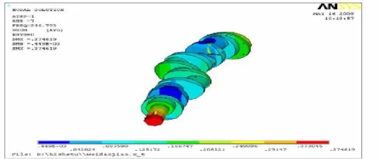
For big volume of the engine crankshaft and solving process of thousands of equation will be produced, it is not possible to calculation of all of the solution, but lower order some of the system of natural frequencies and corresponding vibration model of the dynamic response of the system is the biggest influence, so this paper only gives a significant contribution to the crankshaft the first ten modes, 1-10 order frequency (Hz) is presented in Table1.
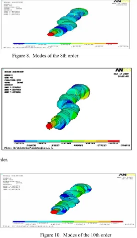
The typical 7th, 8th, 9th, 10th order of the frequency of vibration model is shown from Fig. 7 to Fig. 10.
[image:5.612.214.488.550.665.2]Figure 8. Modes of the 8th order.
Fig. 9. Modes of the 9th order.
Figure 10. Modes of the 10th order
CONCLUSIONS
vibration model, so the crankshaft before a few of the frequency much small order behind the natural frequency of the value. Through the crankshaft vibration model of the dynamic display data and can be found, crankshaft the first six natural frequency for the corresponding crankshaft rigid body free vibration, 7th, 8th natural frequency for the corresponding crankshaft bending deformation, 9th, 10th order frequency for the corresponding of crankshaft distortion of the crankshaft vibration in the process, bending and twisting of the crankshaft is the main deformation form, along with increased frequency, dangerous vibration mode and could happen, the vibration mode is bending and twisting of superposition, in a certain frequency range even into waveform distortion, the crankshaft on both ends of the bearing parts will be under a lot of alternating load, so the stiffness and strength of the ends of the bearing should be strengthened.
Crank arm and spindle neck, crank arm and the neck is linked to the crankshaft vibration in the danger zone, the vibration model figure can be found they were crankshaft vibration of the largest regional deformation, therefore in the design process of the crankshaft should fully consider the crank arm design parameters and crank arm and connected the crankcase in the size of the round, crankshaft modal analysis of the crankshaft is the important parameters of design, it is the follow-up crankshaft simulation and optimization design of MES important data and the analysis of the process of starting point.
ACKNOWLEDGEMENTS
The authors acknowledge the financial support from the Natural Science Foundation of China (51505071).
REFERENCES
1. Z.H. Wu . 1982. Car Engine Design, National defense industry.
2. K. Zhu. 2008. UG NX5 Chinese Mechanical Design, Beijing: people's post and press.
3. Fried J. 1973. “Curve Fitting by Spline and Akima Methods: Possibility of Interpolatio Error and Suppression, ” PHYSMED BIOL, S0031-9155.