2016 International Conference on Artificial Intelligence and Computer Science (AICS 2016) ISBN: 978-1-60595-411-0
Computer Virtual Technology Used in Nc Machine Tool Compensation
Ming SONG
1and Yong-min JIANG
2,*1Department of Mechanical Engineering, Chengdu Technological University,
Chengdu China 611731 Email: [email protected]
*Corresponding author
Keywords: Component, Physical control model; Dynamic, Interpolation method, Virtual simulation.
Abstract. This paper presents a comprehensive virtual simulation model for CNC systems. The Virtual CNC (VRCNC) has a modular architecture and the special function. It can show movement process and the result, it can also show the effect of different movement mode, the displacement, velocity and acceleration of the process, the rationality of interpolation method and the motion control method. Additional CNC modules can easily be prototyped and integrated to the VRCNC by the user. Various application examples are presented which include building of physical dynamic control model, the prediction of the displacement, velocity and acceleration of the process, and the process of secant instead of curve. It can show closed loop drive dynamics. Detailed experimental verification is presented for each algorithm.
Introduction
It has always been a problem that the dynamic error of NC machine tool is tested, judged, and controlled. Before processing, numerical control system should predict motion process, show the movement and motion parameters influence on machining precision, in the process of machining, it should correct the problems and improve the way of movement to improve the dynamic precision. Therefore, the numerical control system need to increase the function of virtual reality and involved in the control, in order to overcome the numerical control system faults, to improve machine tool.
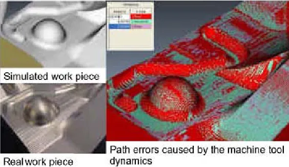
A recent report states: By comparing the simulation result of machining instructions and the actual testing value of machine tools, G. Pritschow and S. Röck, reveal that on all machining points geometric errors somehow exist, which are produced by dynamic parameter error. It is most serious on the big curvature part[1]. It is shown in figure1. Y.A ltintas and K. Eykorkmaz [2] worked on the curvature’s influence on machining motion for solving movement acceleration control problems. The curvature was divided into pieces according to the curvature optimization law: the bigger the curvature is, the shorter the machining length is in a unit time. K. Erkorkmaz, Y. Altintas, C.-H. Yeung presents a comprehensive virtual simulation model for CNC systems, it is good way for dynamic control and should be further developed. [3, 4, 5, 6]
Virtual reality is generated by computer, therefore, people can through the use of all kinds of special equipment and "projection" to a kind of special environment. We use VR CNC to show motion process, show the movement and motion parameters influence on machining precision, and we use it find some dynamic problem for correction.
Virtual Reality Technology The Development of VR
operating, virtual reality has made a qualitative leap in technology. The "reality" in the virtual reality is refers to any things or environment in the physical sense on meaning or function exists in the world, it can be achievable, actually also can be in fact difficult to implement or not at all. And "virtual fitting" refers to the meaning generated by computer. Virtual reality is generated by computer, therefore, it is a kind of special environment generated by computer. People can involve in the environment using all kinds of special equipment, and to operate and control environment, to achieve the special goal, in other words man is the master of this environment. The essence of virtual reality is the communication technology between human and computer. It can support almost any human activity, applied to any field.
Figure 1. Identification of path errors via simulation.
The Essence of the VR
Virtualization is the technology which changes physical resources too logical to break the barriers between physical structure resources for manage. In the future of virtual world, all resources transparently run on a variety of physical platform, the management of resources will be according to the logical way, resources automation of distribution is fully realized, and virtualization technology is the ideal tool to realize them. Virtualization environment requires a variety of technical coordination: server and operating system virtualization, storage virtualization, as well as the system management, resource management and software submission, the applications environment consistent with the virtualized environment. Because of the virtualization, companies no longer need to build costly data center, can realize long-distance backup. This is very attractive for users.
Design the Dynamics VRCNC
The destination of virtual manufacturing technology is to design a completely digital factory, where the machine tool and part is modeled, produced with optimized process parameters, and resulting errors are predicted with corrective actions being taken in a computer simulation environment. An essential step in achieving this goal is manufacture process modeling and the construction of virtual prototypes that accurately represent the dynamics of machine tools and manufacturing processes. This paper presents a Computer Numerical Control system having virtual model which have experiment data center used in a specific machine tools.
contour errors to different part programs, and make necessary changes to the feedrate and toolpath, in order to avoid tolerance violations due to servo errors.
The simulation accuracy of VRCNC relies on the utilization of realistic mathematical models to describe the dynamic behavior of each component work. This is achieved through elaborate modeling of the feed drive dynamics, the character of a specific machine tools, trajectory generation algorithms, control laws, and nonlinear characteristics of the feed drive such as friction and backlash, all of which influence the overall tool positioning accuracy.
Various applications have been developed, which take advantage of the Virtual CNC’s accurate simulation capability in predicting and improving the dynamic performance of real CNC machine tools. These are:
•dynamic control model for feed drives;
• prediction of contour errors for part CNC programs; • prediction of velocity and position;
• prediction of contour errors and acceleration; •sharp corner trajectory of physical control method; •contour error condition monitoring
Physical Dynamic Control Model
The Relationship between Geometric Space and Physical Motion Space
Domain D (T) is a subset of normal space. Defining motion space as: for any trajectory function y = T (x), let x (x1, x2, ... xn) are orthogonal base coordinates. Additional definitions: xi = xi (t1), the coordinates xi (t1) change with time parameters t1, while T is the mapping operator, that is,
( ), ( ), , ( )
T )
(t1 x1 t1 x2 t1 x t1
y n (1)
This is not only a usual parametric equation of geometric function, but also a motion equation for displacement called a displacement equation, which includes only displacement parameters. The displacement equation is the same as a general geometric function. On one hand it stands for the corresponding relation for geometric parameters, on the other for displacement of dynamic relation. Its differentiation yields motive parameters.
If dependent variable y1, y2, ..., yn are continuously differentiable to the independent variables x1, x2, ..., xn, while the independent variables x1, x2, ..., xn are continuously differentiable to the new variable t1, variables (y1, y2, ..., yn) will be continuously differentiable to new variable t1. The principle is similar to the composite function derivative rule. The partial derivative chain rule has a similar formula. When the existent conditions of the inverse function and the implicit function is met, one to one correspondence between t1 and (x, y) can be built in the vicinity of each of the corresponding points y = (y1, y2, ..., yn), x = (x1, x2, ..., xn)
The Close Relationship between Orbital Function and Motion Parameters
Make derivative of the equation (1) of motion displacement to time t1 at both ends:
t x x T t t t t t x x T t t t y
v n i
1 i 1 1 i n 1 i 1 y d d d d d d d d d d d d i i
That means y velocity is equal to the product of the change rate of time and the derivative of track function to geometry parameter t. Acceleration, and jerk expression can be launched in a similar way. These expressions have a common structure: let E, E1 be normal linear spaces
E ) (T
D ,N(T)E1,x(t)D,t⊂[a,b]
1 2 2 i i dt dt dt dt ) t ( xT
(2)
Order: R1Ti[x(t)],
1 1 2 d d d d d d t t t t t t R 2
2
(2) is divided into two parts R1 and R2. R1 is an operation about space parameter t. It equals the production of arbitrary function Ti about t and the differential of a geometric parameter to reference time. The value of the functional determined by the trajectory function does not change over time. R2 is the differentiation of reference time to standard time, making it an operation about time. Reference time is the actual motion process. Its differentiation to standard time is a changing regularity, updated and measurable.
The motion process can be described as those geometric parameter changes with parameter t, in which t changes with reference time and reference time changes with standard time.
Movement Differential Equations
Trajectory function is the mapping operator between three-dimensional coordinates. It is also one of the mapping operators in sobolev space. Any coordinate variable can be expressed by other coordinate variables. Let us suppose that yi is a variable to be studied. Its equation 4) can be gotten from the trajectory function. The form of motion can be chosen by people; Motion equation can be derivate from equation 4).
x t ),x t ), ,x t )
)t (
yi 1 fi 1( 1 2( 1 n( 1 (4)
i ni
x
if
1
ix
yi
v
v
(5)) v ( ix 1 2 ix 2 2 yi i n i
i i x
f a x f a
(6)
i ni
a
a
1 2
ix (7)
i ni ix
v
v
1 2 (8)While: xi= xi(t1), x´i= vi(t1), x"i= ai(t1).
For any parameters t1, the operator mapping is a set of functions fi, including the differential equations of motion. For specific parameter values, operator mapping is a set of numbers, fi0, including displacement, velocity and acceleration values.
Virtual CNCArchitecture The Composition of VRCNC
[image:4.612.95.522.690.731.2]The architecture of the Virtual CNC is shown in Figure 2. The processing programming module will write the processing program according information related to the processing parts with provisions code and symbol at certain format. Trajectory generation module will turn the program into geometric parameters of the trajectory path. Motion planning module converts geometric parameters to motion parameters. Virtual module, according to the motion parameters, simulating machining motion process, showing the development process of various events, predict about physical condition,
Figure 2. VRCNC system architecture.
forecast precision, in the case of operators to participate in, modify part of the motion parameters. Motion control module, in different moments of the program period, turn the revised motion parameters into driving instruction, making all kinds of signals and command, control driver module for a series of automatic processing.
Modeling of Virtual NC Machine Tools
The virtual module can be configured to emulate the dynamics of direct or geared drives. Characteristics of the amplifier, motor, axis inertia, friction, and drive mechanism can be fully defined, including nonlinear effects such as quantization, current and voltage saturations, stick-slip friction, and axis backlash. Experimentally identified or analytically predicted high order drive models with structural resonances can also be incorporated. The feedback can be configured from a combination of linear or angular position, velocity, and acceleration sensors, each with its user defined accuracy and noise characteristics. When the Virtual CNC is assembled, its performance can be assessed by running various part programs and evaluating the servo tracking and contour errors, as well as axis velocity, acceleration, and jerk profiles, and motor torque and power histories. It is also possible to conduct frequency and time domain analyses, which aid the user in evaluating and improving the stability margins and servo performance of the VRCNC axes.
Every NC machine tool has its own characteristics. It can be converted to a logic process, a rule, and be used to establish the virtual NC machine tool model.
Application Examples
To Show the Process of Secant Instead of Curve
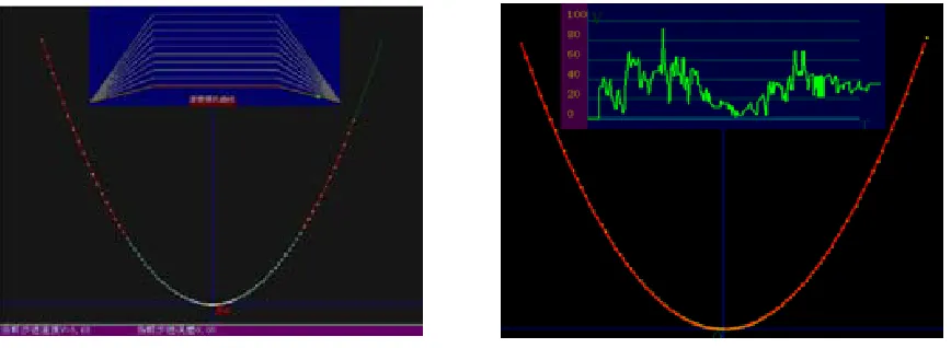
Known equation y = x2 x ≥ 0, planning speed v = v (t), Planning acceleration a = a (t), the curve is replaced by the secant first, on each line, using the linear control mode to control it. The control results of movements are shown in figure 4, Figure 4 shows the parabolic trajectory.
[image:5.612.98.532.416.575.2]
Figure 3. Simulation of parabola trajectory. Figure 4. to control parabola with free.
Figure 3 are micro chip mapping experiments, it uses a straight line to replace the circular and linear motion control method to draw lines, arcs and parabola. Figure 3 is the simulation of the parabola drawn graphics by the way of a straight line to replace the circular and linear motion control method. The speed mode: start-uniform acceleration, run-time uniform speed, at the end-uniform deceleration to stop.
The Motion Parameters Control of Any Motion Law
Experiment content: changing the rate of user-defined time and standard time, changing the feed velocity in a random way, and studying the trajectory tracking process.
of random adjustable speed. It makes the growing rate of the parabola trajectory change in any way, though the motion will not be derailed. This shows that controlling the change of reference time can control the process of motion.
When the ratio dt/dt1 changes, the geometric change rate keeps steady, so there is no re-planning problem. The simulation result is shown in Figure 4.
Acceleration Shock Produced by Linear Direction Change of Curves
[image:6.612.221.392.254.374.2]It always produces error paragraphing according to the curvature and straight line instead of curve. Assuming that trajectory movement is uniform curve motion, linear velocity is constant, but the direction mutations take place in line intersection point of adjacent. In order to reflect the direction of the acceleration mutation, it is shown in figure 4 by a simulation program, the simulation results as shown in figure 4, at the top of the figure vertical lines represent the acceleration value of the actual trajectory, Drawing order of isometric helical order: from small to large curvature radius, the corresponding acceleration value from big too small.
Figure 5. the acceleration value is proportional to the curvature.
Conclusions
The VRCNC allows the dynamic behavior of machine tool CNC systems to be prototyped, evaluated, and optimized in a virtual environment. It can be used as a tool in designing machine tools, developing and tuning control and interpolation algorithms, as well as planning manufacturing operations. Application examples have been presented, including contour error prediction, controller auto-tuning, sharp corner path planning, and rapid drive identification, which demonstrate the benefits of VRCNC.
Acknowledgment
The authors greatly appreciate the following sponsors for their support to the study: The natural science foundation of education committee of Sichuan province, (08zb070).
References
[1]G. Pritschow(1) and S. Röck, “Hardware in the Loop” Simulation of Machine Tools, Machine
Tools [J]. CIRP. 2004, 54/1: M04.
[2]Y. Altintas and K. Eykorkmaz, Feedrate Optimization for Spline Interpolation in High Speed Machine Tools [J]. CIRP. 2003,52 (1): 288-305. K. Elissa, “Title of paper if known,” unpublished. [3]K. Erkorkmaz1, Y. Altintas2, C.-H. Yeung, Virtual Computer Numerical Control System [J]. Annals of theCIRP. 2006, 55/1.
[4]Altintas Y., Okwudire CE Dynamic Stiffness Enhancement of direct-driven Machine Tools using sliding mode control with Disturbance Recovery. Annals of the CIRP 2009, 58(1): 335–338. [5]Li Jie, Wei Qing. Robot path planning and control methods at no reference time. [J]. Robot, 2001, 23 (1): 11-14.