2016 International Conference on Artificial Intelligence and Computer Science (AICS 2016) ISBN: 978-1-60595-411-0
Lower Back Joint Torque Relief Frame Mechanism for Lifting
a Heavy Object by Hand
Hajime YAMAMOTO
1,*and Hideki TODA
11Dept. of Electric and Electronic Engineering, University of Toyama, Gofuku Campus,
3190 Gofuku, Toyama, 930-8555, Japan Email: m1671037@ems.u-toyama.ac.jp
*Corresponding author
Keywords: Lower back joint torque, Lifting heavy object by hand, Hard material support frame, Three points support, Lower back bending force support.
Abstract. In this paper,a novel lower back joint torque relief frame mechanism was proposed. Then the function of proposed mechanism was evaluated by calculated value of lower back joint torque. There are many tasks that are required to unnatural postures and difficult hard work that mechanization is difficult in a wide range of fields such as care, logistics and agriculture. In our method, lifting a heavy object load by the subject arm is reduced by using a proposed mechanism which holds the subject's lower back joint at the chest, the lower back and the thigh. In order to consider the function of the mechanism, an experiment of one subject lift 10.0 kg object was conducted. At this time, the forces which occurred at the chest, the lower back and the thigh were measured by load cells. From the experiment, the proposed mechanism was able to reduce the values of lower back joint torque. Further, the values were at least 2 Nm. The proposed mechanism has a function which reduces the load of the lower back by lower back joint torque relief.
Introduction
In this paper, a novel lower back joint torque relief frame mechanism which holds the subject's lower back joint at three points (the chest, the lower back and the thigh) was proposed. There are many tasks that are required to unnatural postures and difficult hard work that mechanization is difficult in a wide range of fields such as care, logistics and agriculture [1]. Especially, the load of the lower back is a serious problem in recent years and there is a necessity for a method to reduce the burden on the lower back [1]. Our aim of this study is that we consider about the lower back joint torque when the subject has held a heavy object by one's arms for to reduce the load on the lower back. We developed the lower back joint torque relief frame mechanism which fixes the subject's lower back joint. It makes possible by that the subject has received the forces at the chest, the lower back and the thigh by the proposed mechanism.
Previous Study
Generally, many power assisting systems can realize heavy load lifting movement support by rotating the hip joint using motor(s) or actuator(s). Power assisting systems adopt the way of joint rotation control of the hip joint and it can support the rotation of the hip joint movement [2, 3, 4, 5]. However, when we hold a heavy load by the arm, bending forces of the hip joint as well as bending forces of the lower back would be utilized at the same time.
Method
Fig. 1 shows the proposed novel mechanism of bending support of the lower back joints by using hard material support frame. Fig. 1a shows the structure of the proposed mechanism. Gray line (Fig. 1a) is the hard material support frame (SUS304). The proposed mechanism holds the upper body at the chest, the lower back and the thigh.
Figure 1. Our proposed lower back joint torque relief frame mechanism. (a) Structure of the proposed mechanism (b) 3D cad design illustration (c) 2D schematic view (d) Pictures of the mechanism(top: front view, bottom: side view).
[image:2.612.86.536.569.682.2]Fig. 1b shows 3D cad design illustration of the mechanism. We describe the mechanism how attached the body by Fig. 1b. In (C), there are soft rubber pads on the thigh and it connected to the frame via under the crotch at the under the hip. Further, the pads on the thigh are wrapped on the frame of the thigh, and it connects to the frame which passed under the crotch. In (B), the frame is positioned on the lower back by using some soft rubber material. In (A), there is a rubber pad at the chest and the pad is connected to the frame.When the subject holds a heavy object, it can be realized fixed posture by using the proposed mechanism as Fig. 1c.
Experiment
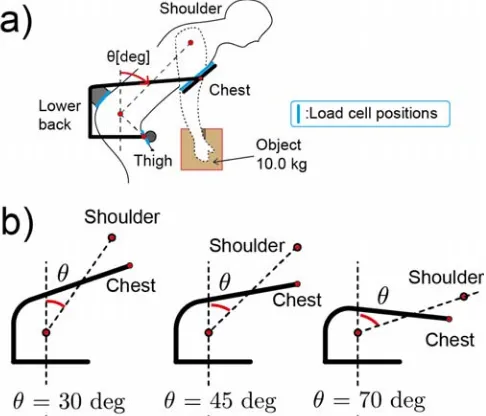
[image:3.612.185.428.177.385.2]In order to consider the function of the proposed mechanism, we measured the forces that occurred between the mechanism and the body (at the chest, the lower back and the thigh) by using load cells when one subject have lifted 10.0 kg object. Then, these forces were measured when the angle of the lower back θ was 30, 45 and 70 deg (Fig. 3a). In order to fix the subject's lower back angle in 30, 45 and 70 deg, we developed three support frames that were bent stainless pipes (Fig. 3b). In addition, we calculated the torques around the lower back joint by using measured forces. Here, lengths of the body were used as moment arms.
Figure 3. Experimantal condition. (a)Blue signs show the positions of three load cells(FC23, Measurement Specialities
Corp.). The definition of the subject's lower back angle. (b)The three support frames(maintaining the subject's lower back angle as 30, 45, 70 deg) were prepared.
Result
Fig. 4 shows calculated lower back joint torques M [Nm]. Further, a blue line in Fig. 4 shows the estimated lower back joint torques Me [Nm] when the mechanism was not attached. M was a very
small value compared to Me. In 70 deg, the values of the lower back joint torque M and the estimated
lower back joint torque Me were respectively 1.88 ± 0.81 Nm and 46.0 Nm. Therefore, the lower back
joint torque was reduced to M/Me = 1.88/46.0 = 1/26 by using proposed mechanism. Even in other 30
and 45 deg, lower back joint torques were similarly reduced by using the proposed system. In all cases, our proposed mechanism was able to reduce the values of lower back joint torque. Therefore, the values were at least 2 Nm.
Figure 4. Comparison of lower back joint torque M and estimated lower back joint torque Me.
Conclusion
In this paper, a novel lower back joint torque relief frame mechanism for lifting heavy object was proposed and evaluated. In our method, lifting a heavy object load by subject arm reduced by using a proposed support system which holds upper body at the chest, the lower back and the thigh.
In order to consider the function of the mechanism, we conducted an experiment of one subject lift 10.0 kg object. At this time, we measured the forces that occurred at the chest, the lower back and the thigh. Our proposed mechanism was able to reduce the values of lower back joint torque. Therefore the values were at least 2 Nm. The proposed mechanism has a function which reduces the load of the lower back by lower back joint torque relief.
Acknowledgement
This work was supported by JSPS KAKENHI Grant Number 15K12598.
References
[4] H. Sato, O. Nanka, K. Kobayashi, H. Matumura, T. Hashimoto, H. Kobayashi, Development and quantitative evaluation of the hip auxiliary muscle suit, Japan Society of Mechanical Engineers (C), Vol. 78, No. 792, pp. 2987-2999, 2012.