STUDIES IN I~':FBABED SPECTRCSCOPY
Thesis by
Philip Ray Y.ennicott
In Partial Fulfillment of the Requirements For the Degree of
Doctor of Philosophy
California Institute of Technology Pasadena, California
ACKlWI.JLEOOMENTS
ABSTRAC':'
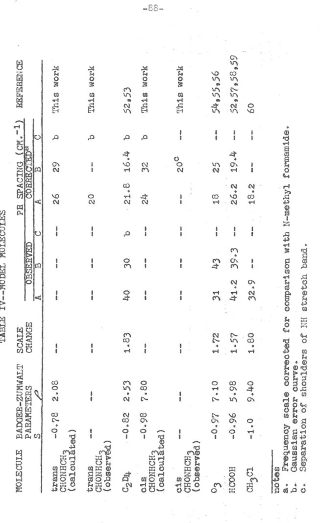
The modernizatlon of a vacuum gratlng infrared spec-trometer is described. Experiments using this spectrometer on l';-methyl forrnamide in the vapor phase are descrlbed, and the results are interpreted in terms of the position, shape, and lntensity change with temperature of the vibration bands of this substance. It is concluded that N-~ethyl forrnarnide exists in two isomeric forms in the vapor phase. The less abundant form 1s the cis isomer which lies 1.4 kca1. above the trans isomer.
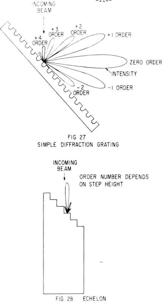
An echel1e-type grating used with this spectrometer is shown to have an unusually wide and flat efficiency curve. This is asoribed to a scattering phenomenon in which both faces of a groove participate. Mathematioal analyses based on both the Kirchhoff theory and on the Rayleigh theory are shown to predict the broad reglon of high efficiency for this grating.
TABLE OF CONTE!\'TS
I THE MODER1'UZATION OF AN H:FBABED SPECTROMETER 1
II A S'l'UDY OF r,~-j1ETHYL FORMAMIDE m THE INFRARED 43
III PROPERTIES OF AE ECHELLE GRATmG I!:\ THE nIFRARED 108
- 1
-SECTION I
THE MODEffi~IZATION OF AN INFRARED SPECTROMETER INTRODUCTION
This section of the thesis will deal with work in-volved in modernizing the vacuum grating spectrometer described by Badger, Zumwalt, and Giguere in 1948. (1)
The many novel features of this instrument make it par-ticularly well suited to infrared spectroscopy of a
research nature as opposed to that of a routine nature for analytical purposes. The instrument employs a diffraction grating as the primary dispersive element instead of the more common prism. It has been designed for the use of a rather large grating (200 mm. x 150 mm.) allowing one to employ narrow slits for high resolution. It has been de-signed as a monochromator rather than as a spectrometer or spectrophotometer, allowing a great deal of flexibility in its use. With suitable accessories, it can provide a mono-chromatic source of radiation, measure the intensity of
each wavelength of a given source, or compare the absorption or emission spectra of two substances. It has been
-2-The instrument has performed well in a large nucber of studies requiring high dispersion, (2) but pro~ress in infrared techniques() has d1ctated that certain
lmprove-ments be made. It was desired to make these ,improvements while retaining the above mentioned advantages of high dispersion, flexibility, and freedom from atmospheric
in-terference.
To maintain the highest possible resolution, it is necessary to use the most sensit1ve detector available
in order that the slit width may be reduced to the min1mum consistent with a satisfactory signal-to-noise ratio. (4) In tr~ shorter wavelength regions of the spectrum, photo-conductors with relatively wide band-gaps such as PbS, PbSe, or PbTe will be used.(S) At longer wavelengths, one can change to other photooonduotors with smaller band-gaps and operated at lower temperatures, or change to a
thermal-type detector. Of the thermal deteotors, (thermo-(6)
oouple. bolometer, and Golay detector ) the Golay detec-tor 1s the most pract1cal at this time in an application directed toward high resolution.
-J-eacl. other and if individual scans do not cover too Great
B. span hi ,vaveler-8th. Wi tr. the conventional echelette crating used in the infrared, this is the case. With ti'l€ 6rating described in Section III, however, a different situation is encounter~d. ~his grating can be described as one which has an effective blaze which covers nearly the entire rar.ge of gratiL€ ar~le. ?his means two t hir:gs. First, at any grating angle several orders will be strong, ar:d these may be quite close to[,:ether iT: wavelength--much
too close for separation by filters. Second, this unique feature of the gra~int rives one the capability of making laue continuous scans without changing gratir:E orders. Such a capability 1s deSirable, for example, in survey
work. In order to take advantage of this capab1lity without stopping several times during the scan to change filters, a foreprlsm monochromator ~:::; needed. r::'his must be of suf-ficiently high resolution to separate orders. It must also be coupled in some i'/ay \'lith the grating drive so that it will be at the correct settinG corresponding to the par-ticular l'lavelel:gtr. and gratinG order at which one 1s Nor~ir..g.
In order to take advantage of the ffiodern detectors
spec-
-4-trometer: A Golay detector was obtained, and provision was made for the use of other detectors when desired. A fore-prism monochromator was added. An extra range was added
to allow the grating to be used at high grating angles. Finally several minor mechanical and optical chang~s had to be made in connection with these other changes. The various portions of the spectrometer will now be dealt with
individually in more detail.
GRATING MONOCHROMATOR OPTICS
The main dispersive element in the instrument is a Littrow-mounted diffraction grating. The collimator is an off-axis paraboloid of 100 om. focal length, roughly 2)0 x 180 rom. 'Ihe mounting in this instrument is somewhat unusual in that the collimator paraboloid 1s cut and mounted so
that its axis passes approximately through the center of the lower edge of the grating. The Newtonian mirrors thus are close to the center line of the optical system and near the lower edge of the grating (figure 1).
II
-=--•.
~XIT
SLIT---~
----'( PLAN"
NEWTONIANPRISM COLLIMATOR
FOCUS "COL LIM ATOR ENTRANCE SLIT If
---
---:
-~
---"
COLLI MATOR ELEVATION --~---
----::-~
joo
---;;;/
L'Sl
E::.-NEWTONIAN ' PRI SM FIGURE IMODIFIED
GRATING
MONOCHROMATOR
"
SLIT _ GRATING COLLIMATOR FOCUSfrom tr.e dravJoock that provision had to L'€ rr:ade to prever:t overlapping of incoming and oatcoir~ beams. ?his presented some difficulty due to space limitations imposed by the vaCUUr:l housing of the instru.rr!ent, but was accomplished by tLe use of two field lenses, one for each beam, located at the slit and so offset in the vertical directior. that iY.'" coming and outeoir:g beams were separated by the prismatic effect.
The new space problems introduced by the addition of the foreprlsrr; monochromator and the various detectors to be used necessitated a more complete separation of incomlr.c and outf,oing beams. 'This .-ras most easily accomplished by locatine the entranoe al1..a. exit slits on opposite sides of the spectrometer.
~his cpznge in the entrance slit position required a second l:ewtonian mirror. Space limitations precluded tte installation of t:rro separa.te :':e~1tonlans together vii th their associated adjusting mechanisrr;s. Instead, a 900 prism was silvered and used for tt,e tHO ;:e''l'tonians. It 1s required tl:z.t the ti~o !~ewtonian mirrors be placed at an ar.gle with respect to each other of approxili~tely 90°. The paraboloid axis must bisect this angle. ~his is automatically fulfilled by tl1e use of the prism with its right-angl e edge on the
axis. 'The pr1sm 1s mounted or: a table \'/hict can be til te(l and rotated for mak1ng the necessary ad~ustmer.ts.
'Ihe exit optics are si:.,llar to the image redJ;.cer
de-scribed by Greenler. (7) 'Ihe exit slit is about one inc;-, ber.ind the larger mirror, rather than at 1ts surface 8.S i[~ Greenler's system. This moves the real 1mage formed b~' tl;e smaller mirror farther beh1nd its s~rface and thus reduces tl~ demagnificatlon. ~he optical diagram is shown in
figure 2.
The more usual arr£lDcen;er.t ~;r,en using a Golay detector WOuld effiPloy a toroidal mirror. 'Ih1s produces a rather diffuse image, but this could be tolerated with the Golay.
'w"lth a photoconductive detector, r:owever, the sensitiv1ty
varies as llarea, and there 1s an advantage in havine the
smallest image of the best quality possible. This systeG allows one to obtain a very high quality i:;:ag6 \</ith a
derr.a,s-niflcation of 1:8 '.,/hile us~ng h:expensive sp:~erical mirrors. Greenler has shown that spherical aberration is eliminated
(to the third order) and that coma is insignificant with this syste:n.
~he actual arraneement uses a 7" mirror from an arc ;notion picture projector l&mp for t-tl and an alurninized ophthalmic lens for M
2
.
0
em
MI
15
.
5
em
EXIT
OPTI
CS
FIGURE
2
0.7
em
l
f-I
-"TI--REAL
IMAGE
FORMED
BY
MI
(./26
X
SLIT
SIZE
)
"-
VIRTUAL
IMAGE
FORMED
BY
M2
(.137
X
SLIT
SIZE)
,
co,
1.7
r
-".
-carriace. It can be rotated about the horizontal and ve
rt-ical axes by adjusting screws. M2 is attached to a short
side arm welded to the casing <figure
J).
This ~lrror con-stitutes part of the vacuu~ seal. A 7 m~. hole is drilled
in trie center and the potasslUIIi bromide exit window cemented
over the hole. It has been found that the slight alteratiOi::
of the focus of thls mirror due to evacuating the casing is
insignificant. 'Ihe mirror ltounting is provided with threads
which screw into a plate and provide for adjustment of the
focus. Upon reaching proper focus the threads are sealed
;~ith Glyptal varnish. ':'he plate f1ts against the end of
the s ide am. a:cd can be moved a bou t over its "0" ring
seal to provlde for adjustment in the vertical plane.
~he Golay detector rests on a small bracket attached
to this side arm. Its entrance window is placed in contact
with the exit wlndow. The position of the detector is adjusted horizontally by moving: screws in slotted holes,
and vertically by a set of shilts.
In passing, it should be noted that certain difflculties
have been noticed with this detector. There is wide
varia-tion in performance between apparently satisfactory
detec-tor heads. Also, the adjustment provided for focusing the
grid inside the detector upon itself depends pr1mar11y on
SLIDING ADJUSTMENT
OVER
110"
RING SEAL
-10-CLAMP
GLYPTAL SEAL
SPECTACLE LENS
.----
-
KBR EXIT WINDO
W
~'CANTED TO A
L
LO
W
FOR DOWNWARD
TILT OF BEAM D
UE
TO OFF - AXIS
COLLIMATOR
MOUNT FOR M2
-1;'
-transla tion of the grid. ~ls results in an extrerrel;y difficult adjustment to make--one best described as hit or miss. 'Ine manufacturers (Eppley Laboratories) have recently
offered a u:ounting of improved design which unfortunately
cannot be used with the detector heads supplied with the
old mounting.
FOREPRISM OPTICS
The original design of the instrument prov1ded for
the future addition of a forepr1sm monochromator 1n a
iVadsworth mounting in the sidetube containing the detector
and entrance optics. This WOuld create the problem of
aligning two parts of the spectrometer on individual
mount-ings. \ii th the exercise of some ingenuity it was found
possible to accommodate a foreprism monochromator witt Littrow mounting on the same carriage as the grating
mono-chromator. 70 accomplish this in the limited space
avail-able it was necessary to locate the prism monochromator on
a level below the grating monochromator and to fold the
optical path at one pOint. The optical arrangement is
shown in figure 4. Tne collimator, M
2, is a 40 crno
spher-ical mirror. M) is a flat plate mirror installed to fold
I
!
!
I
I
/ I
/
;-Ms
/
M3
VERTICAL 01 STANCE 11.5
em
PLANE MI
RROR
•
PRI
SM
\
LiTTROW MIRROR
M4
FIG.
4
•
FOREPRISM
MONOCHROMETER
OPTICS
CO
LliMA
T
IN
G
MI
RROR
---=---~
-
1
3
-horizontal plane containin[ the axis of the colliffiated
beam. ~hls is necessary to allow the prlsffi monochromator
to be placed below the gratlng ~oDochromator, but has, as
a consequence, a rotation of the slit lffiages wlth respect
to each other.
70 study the aberratlons lntroduced by using the
col11-mator so far off-axls, a prelimlnary model of the monochrom
-ator was made and tested. It was decided that a resolution
11ffilt 0.1 micron at J microns would be requlred to properly
isolate the grating orders. It was found tr£t aberrations
became serlous if a much smaller resolution 11mlt was
attemp-ted, but that for 0.1 micron, they would not be lmportant.
M
J can be replaced by a correctlon plate lf lt should ever
become necessary to improve the resolutlon. In practlce,
the potaSSium bromlde prlsm can resolve the yellow doublet o
of the mercury spectrum at
5769-5790
A.Space limltations caused by the large concave mirror
in the exit optics made it convenient to place the foreprlsm
before the gratlng monochromator i:: the optical path. Space
11ffii tations caused by the narrov, carrlage on whicr: it was
wlshed to mount the foreprism dlctated that lt be designed
so that lts resolution i'lould add to that of the grating.
There will be occasions cn which lt is desirable to remove
to increase the energy available. Consequently, tte
intermediate and exit slits of the double monoctromator r{el"e made so that they could function as a unit \'/i th tte Eratlng monochromator wten the foreprism is not being used. Since only one of the two slits of a foreprism need be
precisely made when the resolutions add, the entrance slit of the foreprism was designed to be a fixed slit. Several slits of various sizes are provided mounted on plates \ihicL
can be rapidly substituted.
':'he above design considerations were made primarily on the basis of mechanical convenience, but they do have an important bearing on the performance of the instrument
which is worthwhile to point out. If the intermediate
slit were r.Jade the ';Tide slit of the t\ .. o foreprism slits,
tte wavelength which was passed by tbe instrument would depend on the coupling bebleen the two monochrornators as
well as on their exnct wavelength settings. Nlth the sl its arranged with the primary slit the wide one as is tl1e case
with this instru~ent, no such requirement exists on the
coupling between the tvlO n:onochromators. This is fortunate,
since the wavelength calibration can then depend only upon
the setting of the grating, and the grating mounting is
by far the most precise element in the systen;.
of its wide waveler~th range which corresponds closely to
that of the echelle gratir~. In the event that its rel
a-.tively low dispersion and high scatter1ng should become
object1onable at short wavelengths, prisms of sodium c
hlor-ide or glass are available. Each prism is mounted on 1ts
indiv1dual table. The potassium bromide prism ~~ble is adjusted for height and tilt tiith adjusting screws in the
optical bench. When these screws are set, screws in each
of the other two prism tables are adjusted to COl1ror~ to the potassiuc bromide table. In this way each table can
be individually adjusted, wDile the more precise
adjust-ments in the optical bench can be left set for the
potas-sium bromide prism.
Ideally, each prism should be rotated about t~e
vertical ~~is to produce minimum deviation at the midpoint
of its wavelength r8ne~. It has been found more convenient
to make this adjustment using the mercury green line. This
can be done visually by oeserving the position of the ~reen
line and rotating the prism until the line is at its ~ax
imum deflection. ~he loss of resolution due to this is
negligible.
MECHA.~ICAL DETAILS
-16-to produce a movement of the grating table proportional
to the sine of the movement of the drive shaft. This results
in a scale which is linear in wavelength without the use of
a cam (figure
5).
The sine screw mechanism consists of aflat surface attached to a nut which travels on a very precisely-made screw. The flat 1s oriented on the nut so
that the plane containing its surface passes through the axis of the grating table when the nut is in the zero pos-ition. This co~~ition is necessary and sufficient for
produCing the sine function.
The mechanism worked well for an echelette grating where the angular range in which the grating is used is
small, but, for the echelle-type grating to be described
below, a longer range 1s required. A second range slightlJ overlapping the first ~~d extending to larger gratine angles
was consequently added by maklng the followlng changes (figure 5): A seco-ad flat was attached to the slne-screw
nut, facing the first, and making an angle of about 400
with it. The original ball follower was replaced by a barrel-shaped roller with its axis vertical. It could be caused to bear alternatively on either flat. The roller
is connected to a pinion which meshes with a rack on either flat to insure that the roller actually rolls on the flat
GRATI
NG
TA
B
L
E
/
/AXIS
OF
GRAT
I
NG
TABLE
... ... ... ... ... ... ... ... "-~AT
ZERO
POS
ITIO
N
/
...
"-..
PLAN
E
OF
FLAT
...
... COr~TAINS
GRATING
"-..
~AXIS
GR
A
TI
NG
S
I
NE
SCREW
FIGU
RE
5
SCRE
W
/N
UT
r-I
~ IN
EW
HIGH-R
ANGE
FLAT
PO
R
TIO
N
O
F
RACf<
AND
PI
N
IO
N
ir
LO
W
Rt\NGE
FLAT
'--\----_ ... 1-'
(0"
~
DR
IV
E
GEAR
1 -, -,-1[
-rests on the flat, and the rack and pinion mechanism ffierel~ turns the roller. With some care the rack and pinion can
be engaged so that the same portion of the roller is used
each time. 'Ihis arrangement has the additional advantage
that the rubbing of the ball on the flat is eliminated and
calibration should not change on account of wear at this point.
To correspond to the angle which the two flats make with each other it was necessary to provide for two
alter-native locations of the grat1ng and 1ts holder on the
grat-ing table, differgrat-ing by a rotat1on through this same angle. Since the grating holder is mounted in kinematic fashion with three feet resting in appropriate cavities in the
face of the grating table, this was easily accomplished by providing the grating holder with three additional feet.
It was mentioned in the paper describing the original
instrument that irregularities exist in the screw. To
investigate these a Bayleigh interferometer \'las set up on
the grating table as shown in fieure 6. As the table ro-tates, the path lengths through the two plates change rela-tive to one another, causing the fringes to move across the field of the microscope. The plates ideally should have
beveled edges so they can be placed close together at the
apex. This type of plate was not available and the
Imm 3 mm / II II
.1
-HORIZONTAL SLIT ADJUSTED DOUBL E / SLiT / 10mm\
\
, \ 5em 72 em"-
CYLIN DRICAL LENS (8 mm GLASS CANE) SLIT llLLUM INATED BY Hg LAMP) /' ; BEVE LED PLATES WOULD ALLOW SLITS TO BE PLACED CLOSER TOGETHER VERTICALLY FOR BESTFRINGES INTERFEROMETER
-20-gular plates used made it difficult to obtain consistent fringes. One would observe several well-defined fringes followed by a region in which the fringes Nere either very poorly defined or missing altoeether. This condition could
be alleviated to sorr.e extent by very careful adjustrr.ent of the slits with respect to the flats. Because of the poor quality of the frir.ges, the results obtained should be re-garded as il1dications rather than precise measurements.
It \lias assumed that, for small differences in table position, the number of fringes passing the field of the microscope was proportional to the angle of rotation of the
table. A typical set of results is shown in fieure
7.
7fle Veeder-Root counter Which gives the position of the grating drlve was observed, and the number of counts correspondingto ten fringes passing through the field of the observatlon microscope was recorded. This was repeated until about two turns of the d.rive screw had been completed. 'The number of counts for each observation was averaged for the full
two turns of the screw, and the deviation of each
obser-vation from this average was computed. These deviations are plotted as the ordinate in figure
7.
'Ihe abscissa is t he rotation of the screw.revo-+1
(f)
..
f- 2: =>
o
u 0::0
o
0:: a:: w-I
,
..
J
IINCREASING
GRATING
ANGLE
..
INTERFEROMETER
RESULTS
FIGURE
7
-22-lu_tl0{lS) • ':he d.evi~tioy.::; between separate exper1;r_el::ts
-:Jere 8;.,a11 el~ouGL to ass",re one that t:-.e errors observeo.
;-lere ctnracteristic of tl.e screN and not due to
statis-:1 .. e :lost obvious feature 11;' fifure f/
is the cor.:plex forIT, of ti:e curve. It is certainly not
periodic in any inte[ra1 nu:r:ber of revolutions as IL1Eht be
eXgected if tr.e irreGUlarl ties i-jere due to so~;e def~ct
..
-
~.-tLe lathe or. whicr. tr.e screw /{as cut. Cne can ILake an
estir.:ate of 0.06 counts for an averare error. ''::-his
corres-I / -4
pOI,ds to an error of 6,v:A 00) :r.: 10 'Ilr,lcr. is satisfactory
for r01J.tir~e ::".ensure:r.ents. For !Lore precise o:;easurements
[in interfero:.eter rrie;tt be incorporated lY.. the gratlne
IY:onocr.ro,r.ator to produce calibration frir.ges on the recorder
traclag. Attempts to elicr.lnate ttis error by callbratiol':
\.;1 t.t L110"'-1: spectral lines are a9t to be frustrated by the
8:::011 period of tr)e error in co:r.parison "i1 ti: the spacinc: of sUituble calibration lines.
<':'-oe grating drive shaft :;J8sses through an "0" ring
seal .1n tLe vacuurr: casing to a ce~rl.cx. =:;"he grating drive
eotor is rr;ounted, tOfetrler ~litL its reductlon Lear, on
vlbraticr.less IT_cunts on top of the vac\.<um casing, and 1s
cOY~Lected to tbe r:eurbox through l.,m1 versal ~oir:ts. At
tr.e {It,g-test drive speed, 1.0 effec-;; is discerr.ible in the
-2;-:£:oto;.' •
at ~ied~lctio1: ratios of 2L are avallable Wf.02e
1 ') C
-t~_'''''·''--iI T·siY..C ti.e U.Lr,est speed, the s:;ectrt.:.rl; CUY.
B('l.E.l: - .. -.·ed qt ,-, - +'/'e r"'''"e of 0 " ' . ' " ... • - ' r.; / A-L- I'""i''' 1.. " •
. C.r. inter'loG}: systen is ~lrovided to prever;:; overrc;t:!r,1":.[
the r:.ecr.an1cal 11rr.its of the GratiT~[ sere·.... '.:.'h18 is
aet1v::-ted t:, tAO rr.icroswi tGnes ~.o\..mted at e1 ther er.d of the sere;,.
:. rr.anual overl'ide is pro'!1ded to rett,!,!: the r.ut past the
actuatiO!i :"'01:·i., of tr.e s\~ltcb (Ihen reversir.g directlor.. /o.. ;;ip:?er systerr: is provided for keep1nz t.rack of the
t~rat~t''''',£ ,:::sitior. 0-;--: t:~".e recorder crart. r s;"i teh 1s rr.ot::er-tc;rlly c102ed cc. ec:eL :-evolutio:. of the r.:ratlr.r ::ri ve ShF,f~J'
j, 3eco;,d s\':lter: is arranCed to eitter oper. or close or eecl.
ter.ti, revol:;.':;ic1!. "hese tVJO switcr.es are CO!·.r.ected 111
\'!":er. bot!'. swl teLes
nre el.osed -::'1".e potentiometer adds u sn:al1 r..e[utl ve SiCna1
to tLE out::;ut of the detector a..'T.pllfler. '~L'..;s, GJ. series of
Lei:,""2tive pips ap-;:e£:'I' 0,'; the recorder tracir:c. .cependin£:
~'or- e&o .. r€volutlor, exce~t the ter:tr, or for eaeL te:1tr,
r·evol\....tio~ .
'_,,6
l'e:iesi~T.ed s11 t 11.ecr.ar,lsm for' tr.e lrter-u:ed1ate ar ..o
EXIT
SLIT
,:::--,
F
---r I r.b I I GlJ II
I
I II
I II
~
~
J
I
r.bI
~
~
L_J
CAM
FOR
ACTUATING
SLITS
FIGURE
8
BEARING
CONSISTS
OF
PRE
-STR
ESSED
BALL
BEARI
NGS
ENTRANCE
SLIT
-25-L.e e:::.ds of t...-o bars pi voted to for;r. a sclssors [rec:.m.lstr.
';"te scissors are operated by a can: actlLg on followers at
or~e end of the ar:r.s. '7{"e developffiellt of this can: ls a,;
isosceles trlsy.gle "ILic!: 1s wrapped. around the cirC\.lrr:fer~:.c.c
of a i'iheel ar.d tr.us rr:oves eacn arm e<;.ually. 'Ehe ir:di vld.Lal
jaws are attached to their supports by screws passinG tbro~<~r,
er.lar[ed holes to allo~ for adjustrrent.
~he drive shafts for the sIlt meCh~lisQ and for the
foreprism Li ttro,'1 mirror pass through "0" ring seals hI
the vacc;.uu, casing to the gear box. The gear box contalris
the rr,ec~lanlcal and electrical compor:ents of the electr1c
syster~s \ihich synchronize the forepr1sm and slit drives with the grating drive.
An electric cam performs electrically exactly the same
function as a ::nechu!"ical cam--lmpart1ng a r.-:otion in u slave
mechanism lihicn is some rr:atbematlcal function of the c
ove-ment 1n a Claster mechanlsrrl. rt;echanical ca:;~s are difficul t
and expensive to build and, once finished, car~10t be eas1lJ
readjusted. An electric emn can be bull t easily from
star.d-ard con'ponents, ar.d is easily adjusted. In addltior:., tIie
functlor; [er-er'ated can conver,iently be shifted or ffiultipll'~.:l
by a constm:t factor. 'l.his can only be accomplished t;;ecr.ar:1·,
call;)'
'c::
eOlLplicated l1nkaCes.
-2C,-f1C1.,re 9. '':'he O::1;Jlif1er 1s C01:,"(;ected so that a~iy si~';!al
appear~nL 'cetvleen the t .. w Il~ovable contacts of the
poter:c1or..-sters \'lill 'ce aJ.::plifled. !;md app11ed to the l~otor 1" proper
"rnse t~ 'r~ ;-' e 1 '- tl ' +0 decrepse the
p .. ~ v Cl _ve "n save po ... en orr.ecer v '->
".:.1:e :::otor "Ilal ru~: ur.til trie b-,put to tte
a:r:pll-fier is belo;'/ son"6 thresbold dependll:g on the [p,ln of the
an:pl i.fler, a::ld tr.er: stop.
~.:.ti,out ti:e loadine yet-work tl;is would operate as a
:_o~,al fo:lo;",-\';'~, ':.he slave drive reprodt;cing t.he r:.aster
dri 'Ie :-~ove' ei, t. "'il th t(,e loadinG l~e'.;work 1 however, the
vol taee a"Dove '::',rcl,...l:1 o"!: the [.lovable orr;: of the slave
po-'\,';e:1tio;:)eter car: ce rr.ac1e to closely 33.)prox1mate any
cO!:tir.u-aUG r;oDotonic fur-ction of tte rco'!elCler-t of tLe arn:. 'l'he
only requirel!ler:t is a sufficient nur:iber of lees in the
loadi:::g;:::et\'lOri-:. Sino".:! tl1e 8.ffi1)lifier ar.d IT.otor still tel~ci
to ~;0er; t!'~e vol tareD on the t;"l0 movable arrros equal J the
slave drive v:ill ::ove an amount 'ihich is a function of t;,e
master drive !:lovea;ent. r;::~is f~ction depends or. the settiq
of the load 1.:1[; net,..-or:': t and car. be var1ed ut III ill. By
placlng varyinG reslst::;:rlces between a potentlol.Geter and
i3round a constant factor can be added to the drive fUl-,ctlo~,.
By cimngirif, tr.e total vol tace across the loadlr,g network
ar:d slave poteT:tioILeter, a small portion of the slave car.
MASTER DRIVE
I I I
I
I
I
I
I
~
\
\
\
60rv
-
27-I
I
I'
SLAVEI DR IVE
I
I I
HELlPOT~
ADJUSTABLE
LOADING NETWORK
~ >---i~
\
1
\ < . - - - ; AMPLIFIER
2 PHASE
MOTOR / /
/ / /
/
FIGURE 9 ELECTRIC CAM
-28
-and thus the drive function can be multiplied by a constant factor.
The circuit diagram for the slit cam is shown in figure 10. As can be seen, the function is linear. The
absolute slit opening is controlled by the two variable resistors in the slit potentiometer circuit. The rate of opening is controlled by the switches in the master poten-tiometer circuit. ThiS, of course, is only a very rough
approximation to the required function, but has been found adequate.
The prism cam (figure 11) has a drive function
corres-ponding to the prism dispersion. It is provided with a six-position switch for adjusting the relative voltages on the two potentiometers. At present, four positions are
used--three for the lower range of grating travel in first, second, and third grating orders, and one for the high
range in first order.
The loading network consists of a series of
potenti-ometers connected to two busses by fixed resistors. The taps of the network are taken from the variable arms of the
potentiometers. The total resistances in the slave
potenti-ometer and the loading network are chosen so that approxi-mately 170 times as much current floWS in the loading
6 V 60rv
FIG
10
S
LIT
S
ERVO
S
Y
S
TEM
1200.n..5
K
DPOT SLIT SERVO AMPLIFIER S LIT DRIVE POTENTIOMETER'"
GRATING DRIVE P O TE N TIOMETE R '----' ~-< DPDT ~ DPDT SYSTEM OF SHUNTS TO CONTROL RATE OF SLIT OPENING '-- -----
-_._ --.. ---ABSOLUTE SLI T OPENING CON TR OL4 PO L E
,-
--
--
----1
I 6 POSITIONI I
~
\ I \I I \ 1630 I 1 \ 1
I
~
\fs
4 5 0 0 + \ 6 V 60"-'\ \ \ FIGURE II PRI SM DRIVE 1173 o 6 5460 POSITIONS 1,2,3 FOR RANGE I ORDER 1,2,3 POSITION 6 RANGE II, ORDER I PRISM SERVO
AMPLIFIER GRATING
DRIVE
P
O
TENTIOMETER 5000.n
. PRI S M DRIVE POTENTIOMETERI\ (15 TAP S ) 5000n I \ ----, ,
I I I I I I I I I I I
..J
L
__
_
__
B.65 n
LOADING NETW O RK \ 3 . IBn
\ \ \ 4 0 5 o
6 2 LEGS SHOWN (T O TAL OF 15) T OT AL EFFECTIVE RESISTANCE 32.37.n
-.31-1,.d.eper:de::.:t _ It e-lco serves to ~rotec:' tLe po-c;e:'.;:;ic:,t::'O·
_ Le tHo ~0rvo <.:!',plifiers are pr:::.cticall;/ iclm:tlc::.2. t,.;.
:':.e :1'0,,;,;.; :?ote:,:',tlon:eter recor-G.ar a:::plifier-. A copy of ti-.,::
currer.t "cl.ere is '::C need f'O!~ tile cl:opper cot::noy, to potel:l.i
-)2-operatiOl: 0;1 a1 terr-atine currey,t, the chopper is rerr.oved
8nc. a shortlY!!; plue, whicb cakes the necessary circuit
ci"lanees sutsti tuted in the soc){et. A seccEd pl1.lC; on w(,ic:;
is D.o1..:.nted an on-off at:-::. a reversinr slii tch cc:.n be
sub-sti tuted to provide for !Lar:t;ul oileration.
Ir.. setting up the instrument, the grating
mor.ochrorr-ator was aliened first. '.:"r.e collimator was adjusted as
well as ;ossible visually about the transverse axis (the
!lOrizontal axis perpendicular to tte lone dirr:er.sior: of tLe
carriare) . ::ext, a plurr:b bob \'las suspel-,ded over tr.e cer.te:::
of tr-:e gratine table and its leare observed i":1 the
co11i-n:ator. '.::11e final &djustU!ent of the collirr:ator acout its
vertical axis was rr:ade by causln£ the plumb bob and its
lrr:a[e to coincide when viewed from approxlrr:ately cr..e meter
behir:d the grating table.
A flat was then installed on the cratine table and t.,[ 'f?
table set at zero. '.:"he flat was carefully adj~sted to lie
in a vertical plar.e ''ii th the aid of a spir1 t level. ',:r.e
irriace of a mercury lamp \>1as focused on the exl t 611 t. :he
collin:ator WuS ti1er. glven a riD.al adjustment about the
-33-:::ator coincided ir. tLe vertical direction and that tr.e
ill1,.;.rr::lr.ated portions of the :"ewtor.ian mirrors had tIle sa;:,.e
elen.tior.. '.i'hese t\-JO obS8rvations were taker; as final
evi-C .. ence ;:01' tl':e corr~ct ad~ustn:ent of tte collin:ator mirr'or.
'':''r,e ::edtoi,lar: prise;. Nas g1ver. 1ts final adjustrr;er.t about the lor:["ltw:Ur~al axis b:f derr;andlr:g that the illv. r:.i-r:a ted por·t ion of the entrorce 811 t correspoy.d 1r: a vertlcal directioL wi t~-. the illl.cll.'iT.oted portier, of the exit slit a£
rr.easured. ... i th 8. scale. F'1r;1311y, a 8ecor:d larr.p i~as foc1,.;.sed
on tl':6 Emtr"rnce slit, arlO. ti18 !'evltcniar: pris,,-, ,'illS adjt:.sted
atout the vertical axis to ~roduce a sy~metrical pattern or: -:"Le collixo.tor.
;.'it{, t:-:e gratlr.g rr:onochro:::utor properly o.djusted, t::e
r::11rrors of the foreprlsfL Here adjusted. installed,
2:;0. ti:~e c;r·ating exit slit illun:ir.ated. A card ~la6 t!:en
used to fOllm" tile 11CLt peth thrOUCI-l ';l:e ~onochrotr;ator. ''':ile u:irrors I'lere adj'clsted until a spectrurr; was obtained at
tbe er:trance pup 11 of t:.e i'orepr-isIr..
':l1e colliu:ator ~i~S adjusted to 1:.rinc tLe Spectrurr: to a focus at the poi:::t calculate;} for the prirr.ary slit. :::lth this pr-elirr.i:cary adjustrrer.t; n:adet the iffia.::;e of tLe flat replacir.i3 tl~e zratir:.:; \'HlS observed visually at the er.trance
-34-were adjusted until this image was not cut off by any object
in the foreprism. Finally, the first Newtonian, M
i , was
adjusted to place the entrance beam in a horizontal plane
and perpendicular to the carriage of the instrument. With
the instrument in the casing, the entrance slit was installed
and adjusted to conform to the spectrum.
The above adjustments must all be made with the exit
optics removed in order to illuminate the exit slit. vJith
the entrance slit adjusted and the exit optics in place, a
beam through the foreprism can be obtained for lining up
exterior optics by removing the grating and focusing the
image of a mercury lamp on the intermediate slit with the
grating collimator. The prism Littrow mirror is then
adjus-ted to place the green line on the entrance slit.
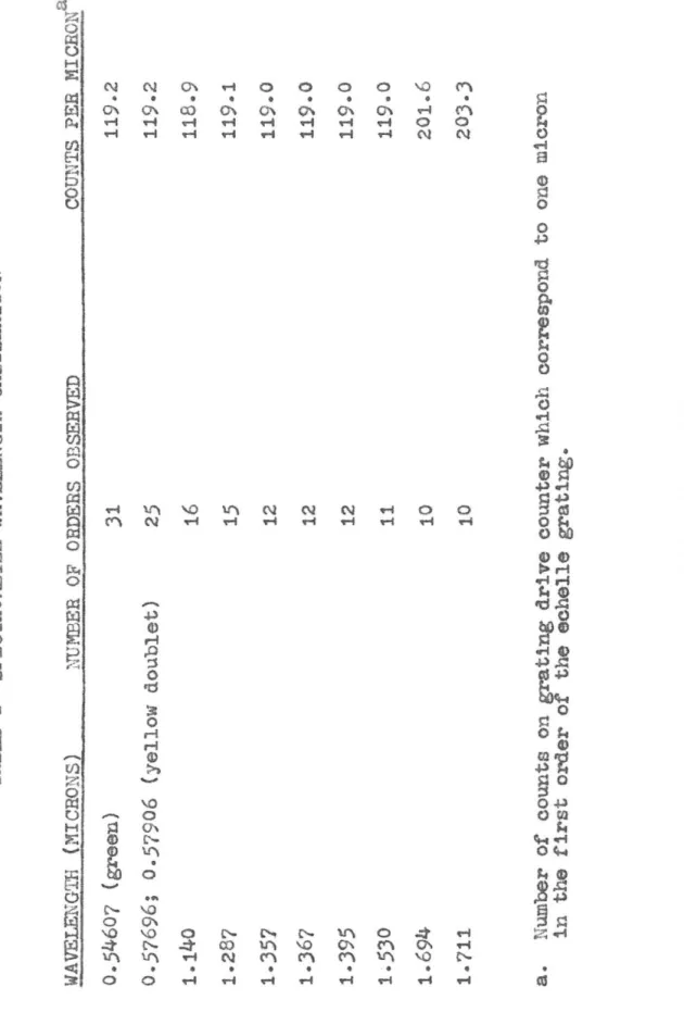
The grating monochromator was calibrated with the wide_
range grating described below. A light from a mercury lamp
was focused on the intermediate slit and the grating
scan-ned throughout its range. The lines listed in Table r(8)
were used for the calibration. They could be observed,
except where overlapped by other lines, in all orders of
the grating range. From the spacing of the lines on the
tracing and the grating constant, the grating angle could
be expressed as a function of grating driveshaft rotation.
," ,
..... ~, '
---:-'-y""'(:"'
'_ .... ,_ ... '-1 .... .1
:.':' .. e exterior op~ics ~'1ere lnte:lded to l..'e as fl~xi blc
possible to acco:;rrnodate differeLt experlrr:ental set-ups.
Lasically 1 t is or.l~' necesse.ry to illumlY.ate the eT.tra..:ce
s11 t .. i tl·, rad.lutlor. ;r.od1.;l.s:.ted ~t ~he arr;pllfier frel.~;;.el'.c~:.
fcrrr.zrr:lde are n1-,0 ... ·1! :1.1'.
r
if.:-ures 12 ::.Y_d 13.an absorption cell ec:~.::lstil~ of ~ steel t .... ';:;e 4" 1:: J.iar::e'...e:;:·
A shroud extei:d::s be:;oLd ti:e ~Ji1.do\,rs to
;-orotect ti1ern frau: drafts, tc conf ine the ',~i trOteY'l used. to
flust: c'</ay atmospheric rr.olstt:re c.r.d CO
2, and to suppor·t
the 450 ::111'1'01'. ':'he chopper and SOl.U'ce ~'lere ;,.ot~r.ted at ,-... ·c .
er.d of a short 7/3" tube soldered in to:: side of ti':e shro .... cl.
A plate or, the o~)posite c!:d Eupports a 40 Cl;. corle ave :: ir':'{)l'
ax provides E; clecr:-cut port. ':.[.e entire cell, inclt::li' L
t •. e sLro,-<cl, 1::; ::eated by c. ref.:istm:ce 'iil:dhl[" lr.Stllated.
''I1th asbestos paper. ':'he L.lrror end of tl-le cell 1s Live::l
uddi t1ot:81 Leat b:: z. lC00 ~l. heath:.£.: rr.all~le to prever;t
"0
'1
RING
SEAL
-CONCAVE
Mi
RROR
-POLYETHYLENE
ENVELOPE
TOTAL
LENGTH
OF
GAS
ABSORPTI
O
N
PATH
160
em
4"
STEEL
TUBE
WOUND
WITH
RE
S
ISTANCE
WIRE
FIGURE
12
STEEL
ABSORPTION
CELL
N2
1N
•
)-~
~
-i"
C
H
O
PPER
,
<b
GLO
BAR
'
---l
7/~'SPE
C
T
R
O-METER
H
O
US
I N
G
SPLIT
TUB
I
N
G
FOR
GA
S
KE
T
-ENTRAN
CE
SL
IT
I W I
""
MAIN
HEATER
POL
YETHYLENE ENVELOPE
\ \ \ I
---'\',
~
N2 ..., AUXILLI ARY HEATER SP ECTRO -METER H OUSING I(STEEL TUBE WOUND WITHbZV
YV\ZS3
RE~~~~~CE
\
/\71
I / FOR WINDOWCONCAVE MIRROR
10em
GAS
ABSORPTION PATH
140 em TUBE FOR ADM ITTING GAS ILLUMINATED WITH HEAT LAMP
FIGU
R
E
13
GLASS
ABSORPTION
CELL
/ RESISTANCE WIRE WOUND CCLQ ("\ () ON GLASS-,--I
F
'l
TlIT
6 . 5 em . I \.,) C ONCAV E M IRROR-39
-more closely than the main portion to prevent condensation
on the windows.
The second set-up was built when more precise temper
&-ture and pressure control beoame important. A glass tube
'tlaS used with a Single potassium bromide Window on the e-''1d.
This fitted into a steel tube wound with a reSistance wire
for a furnace. An auxiliary tube heated ar~ protected the
window, and a heat lamp heated the mirror. The mirror was
held by a brass fitting clamped to a flange on the end of
the glass tube. Contact with the glass was made by "0"
rings to allow for differenoes in expansion. Gases were
admitted and removed through a glass tube passing through a
seal in the end plate and through a hole in the center of
the concave m1rror.
The source, ohopper, and exterior part of the optical
path of both set-ups were enolosed by a pOlyethylene film,
the interior of which was flushed with nitrogen. With the
steel tube, passing dry nitrogen first through the shroud
and then out through the 7/8" tube to the interior of the
polyethylene enclosure praotically removed the effects of
atmospheriC absorptiol'l bands. The strongest water lIne In
the
7
/k
band gave95%
transmission as opposed. to5%
with-out flushing. Because of poorer n1trogen flow, the glass
-40
-CONCLUSION
The instrument with its modifications is shown in
figures 14 and 15. It is believed that the task of
bring-ing the instrument up to date while retaining its
advan-tages of high resolution, flexibility, and freedom from
-43-SEC':'IO;': II
A S'I'UDY OF :;-ME7HYL FOilNAMIDE VAPOR E 'YtIE EPRABED
'].'hi8 section of the thesis wlll present a study of
N-methyl formamlde in the vapor phase. The purpose of t~c
study is to elucidate certain features in the structure a~:.i
infrared spectrum of molecules in the vapor phase i-lh1c]:: CO!:"
tain the N-substltuted. amide group. It is important to do
this for two reasons: In the first place, the
ld~utlfl-cation and characterization of the amide group in a molecule
by chemical meallS 1s difficult. 011 the other hand, it bas
been shmm (9) that the infrared spectrum due to this croup
in a molecule is one of the most stable and re~roducible
in the condensed phases. In the vapor phase of the ~:-sub
-stltuted amides, one might expect the spectrum to be quite
d1fferent, but it 1s not clear exactly what the difference
will be. ~hus. an understanding of the infrared spectr~~
of a molecule containing the !\-substi tuted amide g.t'oup in
the vapor phase is important frorr: an analytical standpOint .
Of even greater importance is the understanding of the
structure of the N-substituted amide group in terms of its
biological Significance. A protein molecule consists of
-44-simplest molecules containing the peptide l1nkage are
the N-subst1tuted amides. Certain features of the
infra-red spectrum have been shown to be common to the condensed
phases of the !,-substituted amides, the polypeptides, and
the proteins. The presence of these features in simple
molecules greatly facilitates the understand1ng of the
same features in the more co~plicated molecules. For this
reason, there has been a great deal of effort devoted to
the study of the condensed phases of the N-substituted
id (10-13)
am es. :{h11e the understanding of the condensed
phases may be said to be quite far advanced, this 1s by
no means true of the vapor phase.
It certainly is not to be argued that the structure
of the N-subst1tuted am1de group in the vapor phase has a
direct b101ogical signifioance. One very definite benefit
can be expected, however, from a thorough study in the
vapor phase of a small molecule conta1ning the group. As
will be brought out beloW, the baSis for the present u
nder-standing of the structure of the amide group in the liquid
phase and in solution is not nearly as well established as
some authors seem to be11eve. Many of the previous
experi-ments, which were intended to establish certain features of
the structure, were based on faulty reasoning and need to
-45-this study, and from other stud1es wh1ch it may suggest,
will facilitate th1s re-examinatlon, and thus contr1bute
to the understandlng of biological problems which lnvolve
the structure of the peptide linkage.
This study, then, is directed toward obtalning a
better understanding of the 1nfrared spectrum and structure
of the r{-substi tuted amlde group 1n the vapor phase. Thls
understanding wl11 be helpful in extending the usefUlness of
infrared tecrm1ques to the qualitative and quantitat1ve
an-alysis of molecules contain1ng the amlde group in the vapor phase, and 1n 1mproving the understanding of the condensed phases of molecules contain1ng the pept1de linkage.
The d1scussion w~ll beg1n w1th a review of the current
understanding of the amide group. wlth partlcular emphas1s
on the N-substituted amide group, in each of the three phases. Experiments will then be descr1bed whlch were performed with the vacuum grating spectrometer described
1n Sect10n I. Finally, a discussion of the results of these experlments 1n terms of the pos1tion, envelope, and
-46-'IRE AMIDE GROUP
'I'he isolated amide group is cornrr.only represented in elementary texts as having the structure shown in fig~re
16A. On the basis of this structure, barring steric
hind-rance, one would expect the molecule to be pyramidal about
the nitroeen atom in a manner similiar to affimonia. One
would expect the carbon-nitrogen distance to be approximately
1.47 ~ on the basis of X-ray data from crystals of other
compounds containing a carbon-nitrogen single bond. (14)
The most reliable data with which to check these predictions
come from X-ray stud1es of crystalline compounds containing
the amide group. corey(15) rev1ewed this field in 1948.
The carbon-nitrogen distance in the amide linkage in a
crystal is found. to be much closer to 1.)0
i.
The confif,"Ur-ation of the atoms about the nitrogen atom is planar, or
nearly so, rather than pyram1dal. The l1terature which has appeared s1nce Corey's review does not make any essential change in this p1cture, although, 1n a study of formam1de, Ladell and post(16) found a deviation from planarity of
around ten degrees.
The above d1screpancy between the predictions based
\
/
C-N
/
\
A
\
+/
C
=N
c!-
\
B
FIGURE 16
FIGURE 17
H
\
/
C= N
)'
\
O~
TRANS
FIGURE 18
\
/
C
~N1/
\
0----
--
---H
CIS FIGURE 19\
+
/
C-
N-H
II
\
o
_4R-second form of the group, shown in fibUre 16B, makes an
appreciable resonance contribution to the structure. A
contribution of the struoture shown in figure 16B would
have the effect of making the molecule more planar about the
nitrocen atom ar~ of shortening the carbon-nitrogen bond
distance. This contribution would also have the effect of
greatly hindering rotation about the carbon-nitrogen bond.
(Flgure 17). If the two groups attaohed to the nitrogen
atom (li in flgure 17) are dlfferent, this hindered
ro-tation will result in two geometrical isomers of the
molecule being possible. In the N-substituted amides, it
is customary to refer to the ~~o isomers as cis and trans
according to whether the and the C-O bonds are in roughly
the same, or in opposite directions, respectively. (Figures
18 and 19).
The X-ray data referred to above show that in the
crystalline state, molecules having the N-substituted
amide group all exist in the trans configuration. The
molecules are linked together in long chains through
hy-dro£en bonds between the carbonyl oxygen of one molecule
and the amide hydrogen of the next.
If the structure of the linkage is understood in the
crystal, and if suitable force constants can be obtained,
-
4>-normal modes of the linkage. With information regarding
the dipole moment as a function of bond distance, the chanL~
in d1pole moment due to the molecular vibration in a given normal tr.ode could then be calculated. Th1s information
could be correlated with infrared polarization data on actual
crystals, in order to obtain the orientation of certain
bonds in the crystal. This would be particularly useful
in de';;ermining the positions of hydrogen atoms, which ca
n-not be located in the crystal with the use of X-rays. A
(18-20)
great deal of work has been done along these lines.
Because of the lack'of suitable data on which to base
the calculations outlined above, most of this work has been
done using an empir1cal approach. Directions of cr~nge in
dipole moment are measured experimentally for simple
struc-tures which have been determined accurately, and then an
attempt is made to transfer this data to other more
COm-plicated structures.
The problem is compllcated by the fact that the normal modes of the peptide linkage are by no means the simple
ones one would expect from a consideration of the posltions
of the bands in an infrared spectrum of a molecule contai
n-lng the linkage. For example, there is a band near 1500 cm;l
which one would ordinarily assign to the carbon-nitrogen
-50-transition moment is not along the oarbon-nitrogen bond, but is inc11ned at some angle to it 1n molecules contai
r.-lug this 11nkage. In addition, if the nltrogen atom is deuterated, the band shlfts markedly in frequenoy,(21)
indicating a contribution of the hydrogen bend to the
normal ~ode of th~ band. (22)
Two studies have been reported which attempt a
quan-titative discussion of the normal modes of the amide link-age. A Japanese group(23,24,25) attempted to calculate the normal modes and their frequencies by transferrlng force constant data from other molecules. Some objections
can be made to this work, and these are discussed in detall below. 'l'he 'best data on the normal modes seem to be tr.ose
obtained by Eadger(26) with the aid of a mechanical model.
The force oonstants of springs linking steel spheres
rep-resenting the atoms of the linkaee were altered so as to produce a set of modes whose frequencies bore the same relations to each other as the frequencies observed 1n the
infrared spectra of molecules containing the linkage. It is hoped that this study will improve the
under-standing of the normal modes. ',Vi th a detailed knowledge
of the normal modes and of the electronic structure of
-51-moment for the various infrared bands, and thus to ~~ke
more useful the polarlzed lnfrared studies on protelns.
In the liquid phase, the exlsteDce of hlndered
ro-tation about the C-!\ bond has been established by nuclear
magnetic resonance studles. The difference in energy levels
between the two pcsslble spin states of a hydrogen atom 1n
a magnetlc fleld 1s of the order of radl0 frequencies. If
hydrogen atorr.s are placed ln a sultable magnetlc field, it
is found that energy will be absorbed at the frequency co
r-responding to the transition from one spin state to the
other. This frequency is accurately known for a free
hydro-gen atom, but, in general, is different ln a molecule. One
effeot whioh changes the frequency in a molecule ls the
shielding by the remainder of the molecule of the fleld
seen by the proton. This results in a shift of the
fre-quency of resonance in a given field whioh is known as the
chemical shift. This shlft can be shown to be proportional
to the applied magnettc fleld.(27)
Conslder a di-methyl amlde. Tne six methyl hydrogens
wlll all show the same resonanoe except for the effect of
the carbonyl oxygen atom on the three which are close to
the oxygen atom. If the three hydrogen atoms are near the
oxygen atom for an appreciable perlod of tlme, the effect
-52-there is rapid exchange of the hydrogenst as, for example,
due to free rotation about the c-~ bond, each of the six
hydrogen atoms will see the same average field and there
will be no spl1tting. Phl11ipS(28) and Gutowsky and Holm(2S)
have studied di-methy1 formam ide and have observed the
field-dependent splitting. Phill1ps calculated frem the
mSQ1itude of the splitt1ng that the exchange rate for the
two methyl groups could be no greater than )8 sec.- 1 •
It has been shown(JOt)l) that molecules contain1ng the
unsubst1tuted amide linkage ex1st in solut1on as dlmers.
Tbese dimers conta1n e1gbt-membered r1ngs formed by two
hydrogen bonds ratber tban long chains formed by many
hy-dror;ell bonds. This does not seem to be the case
with.mole-cules contain1ng the ~:-substituted l1nkage. Hu1sgen and
;'!alz (J2 ,JJ) have done the most sign1ficant work on this
pOint. ?hey report a study of lectarns containing various
numbers of atoms in the ring. A lac tern is a molecule
cm1-talning the amide linkage in which the group attached to
the carbonyl carbon is also attached to the nitrogen, thus
forrnlr..g a r1ng. If the ring 1s small enough, the molecule
must have the c1s configuration about the carbon-nltro£en
bond. In solutions of lactarns, these workers observed a
marked change in the behavior of dielectric constant with
-
5
3
-of the ring reached nine atoms. These changes were
in-terpreted as resulting from the conversion from the cis
form in the small ring compounds to the trans form in the
large ring compounds. The reason for this oonversion seems
to be the preference of the compound to exist in the trans
form when free to do so.
A similar preference for the trans form seems to exist
in all N-substituted amides in the liquid and in
not-to-dilute solution. The best evidence for this preference
is the similarity in behavior of these compounds to the
large ring laotams observed by Huisgen ~A Walz. There
are many other works in the literature, of more or less
merit, whict. support thls contenslon.
Leader and Gormley(34 ) studied the dielectric constant
of liquid amides. They found a large difference between
the dielectric constant for molecules which they believed
to have the cis form and molecules which they believed to
have the trans form. The latter included the N-substituted
amldes. Their l'lork wi th l~-methyl formamide is open to some
criticism. They noted that samples of this compound had
abnormally high conductivities which they attributed to the
presence of methyl ammonium formate. Using a resin column,
they converted the methyl ammonium formate to formic acld.
-5
4-solution, they believed this would have no effect on the
dielectric constant of the ::,;-methyl formamlde.
Hizushima and co-workers(2J) report a study of K
-methyl acetamide using several different methods. They
compared the position of the absorption in the ultraviolet
of N-methyl acetamide to the position of the siffiilar abso
rp-tion of acetone. Their argument \'1a6 that, if only the
structure of figure 16A ltade an appreciable contribution
to the structure of the molecule, the position of the ul
-traViolet absorption due to the carbon-oxygen double bond
should coincide with a similar absorption in the spectrum
of acetone. Experimental observation showed the absorption
to be shifted toward shorter wavelengths in N-methyl
acet-amide. This would indicate that the form of the l1nlcage
in figure 163 contributes to the structure of the molecule,
and thus implies hindered rotation about the carbon-nitroeen
bond in the liquid. Only in highly acidic solutions, in
which only the presence of the form shown in fig~re 16C
was postulated, dld the ultraviolet absorption coinclde with that of acetone.
These workers measured the dipole moment of :J-methyl
acetamide and found it to coinCide with the value which they calculated for the trans form of the molecule, but
-55-portion of the work is highly questionable. In the first
place, the measurement of the dipole moment involves the
extrapolation of the data to infinite dilution. This ex-trapolation is an extremely difficult one to make because
of its nonlinearity. In the published work no comment is
made on how, or with what accuracy the extrapolation is made.
Further, it is stated that a "s1mple vector calculation" was
used to obtain the calculated values of the dipole moments. No details were given of this caloulation. In particular,
it is not explained how the partial double bond oharacter
of the carbon-nitror,en bond is taken into consideration.
The dipole moment of such a bond is certainly not tabulated
in l1sts of bond mou:ents (;5) which are usually used for B.uch
calculations. Finally, it is stated that the contr1bution
of the solvent to the dipole moment is one Debye. Xo very
good reason is given for this estimate, and one can only
notice that it is exactly one Debye which is needed to make
the value of the uncorrected dipole moment correspond to the
observed value.
'l'he Japanese group studied the infrared and Raman
spectra of N-methyl acetamide. These were compared to
normal coordinate calculations made for both the cis and
trans form, and it was shown that the correspondence
the trans form than for the cis fOrffi. ~he ~ormal co-o r~i-r~te calculation was done assuming the methyl and the NH groups to be pOint masses. This approximation can scarcely
be j~stifled in view of the contribution of the !;E bend to
several of the amide modes.
A pair of papers published later, one by Miyazawa, Shimanouch1, and M1zush1ma(24 ) on the trans from of N
-methyl acetamide, and one by MiyaZawa(25) on the cis fo~, attempts to correct this objection to the normal co-ordi-nate calculations. In these papers, the proble~ is treated
as a six-body problem, only the methyl group being treated
as a peint mass. It seems likely that even this is too
creat an approximation. The question is whether the methyl
frequencies mix with the frequencies of the remainder of the
molecule. While one does not like to state flatly that the
stretching frequencies of the methyl group will, or will
not, mix with the frequencies of the remainder of the
mole-cule, it seems probable that the methyl deformation
fre-quencies will definitely m1x with the skeletal modes of
the amide l1nkage. 7h1s fact 1n 1tself would open th1s
work to serious critic1sm.
The calculat10ns themselves could have been improved.
In construct1ng the potential function for the molecule,
-57-constant between two atoms, the bendinc force constant
which tends to maintain the angle between two adjacent
bonds constant, and a repulsive force constant which acts
between atoms at the far ends of pairs of adjacent bonds.
As 1s usual in these problems, the values for these force
constants were taken from other molecules for which normal
co-ordinate calculations have been ~ade, and which bear
some resemblance to the structure of N-methyl acetamide. In some cases the resemblance was faint indeed. For ex-ample, the bending and repulsive force constants for the
group C-K-C' (Le .• the angle between the bonds from the
ni troge11 atom to the carbonyl and the methyl carbons) ar:d for F-C-C" are taken from the propane molecule and the
acetate ion, respectively, ne1ther of which has a nitroGen
atom.
A normal co-ordinate calculation was first made for di-formylhydrazine Which can be regarded as two formsmide
molecules joined together by a bond connecting the two
nitrogen atoms. This is a simpler problem because of the
higher symmetry of this molecule, and the results could
have been useful in choosing values of the foroe constants
for the calculation of the normal modes of K-methyl
acet-amide. To be useful, the force constants used in the calo
-5~-corrected to bring the observed and calculated values for
the normal modes of this molecule into closer agreement.
It was evidently felt that this was not necessary, for the
comment was made that the force constants were transferred
without corrections, despite the fact that some of the
de-viations between calculated and observed frequencies were
nearly 100 cm.- 1
The question of the structure of the
di-formylhydra-zine molecule also arises. The statement was made that
this molecule has the trans structure and is planar. The
evidence for this statement came from X-ray data obtained
from crystals. The environment in the liquid phase. and
also possibly the structure, could be quite different.
It cannot be said that the structure of the
K-substi-tuted amide group in the liquid phase or in solution has
been definitely established, although in view of the work
of Huisgen and ~lalz, it is highly probable that the
mole-cule exists primarily in the trans configuration. From a
consideration of the evidenoe for the two resonance forms
of the molecule, it is probable that the amide group is
nearly planar. ~evertheless. these statements must be
regarded as only probable.
While there may be some justification for saying that
-5
7
-resemble the crystalline phase, which is fairly well
char-aoterized, nothing at all can be said on this basis about tr.e structure in the vapor phase. Here the effects of 1n ter-molecular hydrogen bond1ng which are so 1mportant 1n the
crystal and in the liquid are completely absent, and each molecule acts independently. A consideration of the cis structure in figure 19 suggests that the intramolecular
hydrogen bond might stabilize this structure enough to
permit its existence in the vapor. Such a s1tuation has been observed for ortho-chlaro phenol. ()6,J7)
The work 1n the literature devoted to obtaining a
better understanding of the amide group in the vapor phase
is disappointing. One exception to this is the paper by
Costaln and
DoWllr~()8)
on a microwave study of gaseous formamide. By obtaining the rotational constants for themolecule with ten different combinations of isotopes they are able to determine quite accurately the internuclear
distances and bond angles. The C-II: bond is found to be
somewhat shortened due to partial double bond character.
A deviat10n from plar£rity about the