Effect of Variable Cyclic Prefix Length on OFDM System
Performance over Different Wireless Channel Models
Amar A Al-jzari1, Ivica Kostanic1, Khalid Hassan Mohamed Mabrok2
1Department of Electrical and Computer Engineering, Florida Institute of Technology, USA
2Department of Electronic Engineering, University of Garden City, Khartoum, Sudan
Copyright © 2015 Horizon Research Publishing All rights reserved.
Abstract
A Cyclic Prefix (CP) is a significant feature of an OFDM waveform. It is used to completely eliminate both Inter-Symbol Interference (ISI) and Inter-Carrier Interference (ICI) as long as the CP length is greater than the channel delay spread. By eliminating both ISI and ICI, the CP compensates for the effect of the multipath dispersion; but it consumes a considerable amount of the scarce spectrum and the power. Conventional OFDM uses a fixed and large CP length to overcome the ISI caused by channel delay spread under wireless mobile environment. This approach may degrade the overall spectral efficiency as well as consumes relatively more transmitter energy. Therefore, there is a need to adopt the CP length according to instantaneous channel parameters. In this paper, we presented a method for investigating the effect of varying the CP length on OFDM system performance over different multipath channel models. We estimated the variable CP length based on the RMS delay spread of the channels’ power delay profile (PDP). According to this method, the estimated CP length optimizes the system capacity and improves the overall system performance. We showed that this approach could lead to a mathematical formula presenting the relationship between the CP length and the RMS delay spread of the channels.Keywords Cyclic Prefix Length, OFDM System, Power
Delay Profiles, RMS Delay Spread, System Capacity1. Introduction
Orthogonal Frequency Division Multiplexing (OFDM) has become the most popular transmission technique for wireless communication over wide band channels that exhibit frequency selectivity. In broadband wireless communication, the delay spread caused by multipath fading channel will usually introduce ISI to the receiver. OFDM transmission scheme was devised to improve radio link performance degraded by the multipath fading. Due to its robustness against multipath fading the OFDM is becoming a modulation technique of choice for most commercial
high-speed broadband wireless communication systems. The OFDM is a special form of multi-carrier modulation schemes that is capable of overcoming the frequency selectivity of the radio channels and providing the high data rates without ISI [1-5].
A circular extension known as the CP is generally inserted in OFDM transmission to eliminate both ISI and ICI resulting from the multipath nature of the physical channel. To achieve this goal, the CP length must be greater than the delay spread of the multipath channel [6]. However, the introduction of the CP reduces the bandwidth efficiency and decreases the data rate (system capacity) because it conveys no information. It also disperses the transmitter energy (the amount of consumed power depends on how large the CP length), where the signal-to-noise (SNR) lost due to the CP introduction indicates the loss of transmission energy. Because of the loss of SNR and the bandwidth efficiency, the CP length needs to be chosen optimally. Typically, it is chosen based on the multipath channel duration in a given operating environment [7, 8].
fact is also motivated the use of variable CP length. In 2005, Chiwoo, Youngbin, Panyuh, Hyeonwoo and Jaeweon [12] proposed another method to adopt the CP length via adjusting the sampling rate. The drawback of such as solution is increased signaling overhead. In [11, 12] approach, the Power Delay Profile (PDP) of the channels is fitted into a Negative Exponentially Decaying Profile (NEDP). Based on the NEDP a mathematical formula is derived to estimate the variable CP length for the different channel models. The evaluation of the CP length requirements for different mobile environments is the problem addressed in this research. In this paper, we proposed an approach which can be utilized to enhance the method developed in [11, 12, 15]. We presented a method to estimate the variable CP length based on the RMS delay spread of the channels’ PDP, where the channels’ PDP are not fitted into NEDP but it is scaled by a weighting function to ensure the synchronicity assumption. Furthermore, an analytical method for evaluating Signal to Interference and Noise Ratio (SINR) in OFDM system is utilized in this paper to evaluate the optimum CP length over different channel model.
[image:2.595.314.548.223.294.2]2. System Model Description
[image:2.595.61.293.360.499.2]Figure 1. Block diagram of OFDM system
Fig.1 shows a basic model of OFDM system. First the input binary data are generated and converted to the data symbols by using different modulation schemes such as BPSK, QPSK and QAM etc. Once the sequence of binary values is mapped to a data symbol form, the next step is to generate an OFDM waveform by converting the serial data symbol sequence into a number of shorter parallel symbol sequences. These modulated signals are processed by Inverse Fast Fourier Transform (IFFT) block to transfer the signal from the frequency domain to the time domain. Then, the CP is added to the signals. This CP extends the OFDM symbol by copying the last samples of the OFDM symbol and appending it in front of the transmitted OFDM symbol. The reason for that is to preserve the orthogonality between the sub-carriers, and to allow the receiver to integrate over an integer number of sinusoid cycles for each of the multipath when it performs OFDM demodulation with Fast Fourier Transform (FFT). After adding the CP, the signals are converted to serial form and transmitted through the channel [13]. At the receiver side, a reverse process is performed.
The serial data is received and converted to the parallel form. Then the CP is removed. After removal of CP, the FFT is performed to convert the signals to frequency domain. Then the signals are demodulated using different modulation schemes to get the original binary data [13].
Fig.2 shows the proposed OFDM system model. According to this model, at the transmitter end the signal is modulated and subsequently the CP controller attaches the CP length adaptively to mitigate both ISI and ICI introduced due to the multipath fading channel. At the receiver end, the CP controller detaches the CP length before demodulator in order to recover the transmitted signal.
Figure 2. Block diagram of proposed OFDM system
3. SINR Calculation Method
In this section, we presented an analytical method for evaluating SINR in OFDM system as utilized in [14]. The SINR expression is used in our analysis as function of CP length, PDP, symbol length and thermal noise power. The useful and the interference signal powers are both obtained from the channels’ PDP scaled by a weighting function called “bias function” given as:
𝐶𝐶(𝜏𝜏) =
⎩ ⎪ ⎨ ⎪
⎧ 1, 0 0, ≤ 𝜏𝜏𝜏𝜏< 0<𝑇𝑇 𝑔𝑔 0, 𝑇𝑇𝑂𝑂𝑂𝑂𝑂𝑂𝑂𝑂≤ 𝜏𝜏 𝑇𝑇𝑢𝑢−�𝜏𝜏−𝑇𝑇𝑔𝑔�
𝑇𝑇𝑢𝑢 , 𝑇𝑇𝑔𝑔≤ 𝜏𝜏<𝑇𝑇𝑔𝑔
(1)
Where 𝑇𝑇𝑔𝑔is the CP length, 𝑇𝑇𝑢𝑢 is the useful OFDM
symbol length and 𝑇𝑇𝑂𝑂𝑂𝑂𝑂𝑂𝑂𝑂is the total OFDM symbol length
which is a combining length of the CP and the useful OFDM symbol.
The channel PDP is assumed to have 𝑃𝑃 taps and complex gain with power |𝛼𝛼𝑖𝑖|2 and 𝑖𝑖𝑡𝑡ℎ tap at delay𝜏𝜏𝑖𝑖. The
channel is normalized such that:
∑ 𝑎𝑎𝑝𝑝𝑖𝑖=1 𝑖𝑖= 1.
The SINR per subcarrier due to this static channel, with transmit signal power of 𝜎𝜎𝑥𝑥2 per subcarrier and thermal
noise of variance 𝜎𝜎𝑛𝑛2 per subcarrier, can be written in terms
of useful signal and interference signal power as:
𝑆𝑆𝑆𝑆𝑆𝑆𝑆𝑆= 𝑝𝑝𝑠𝑠
𝑃𝑃𝑖𝑖+𝜎𝜎𝜔𝜔2 (2)
Where 𝑃𝑃𝑠𝑠 is the useful signal power, 𝑃𝑃𝑖𝑖 is the
interference signal power and 𝜎𝜎𝜔𝜔2=𝜎𝜎𝑛𝑛2 / 𝜎𝜎𝑥𝑥2 is the
variance of the additive white noise . The useful signal power is given by:
[image:2.595.359.528.446.504.2]The interference signals power is given by:
𝑃𝑃𝑖𝑖= ∑𝑝𝑝𝑖𝑖=1(1− 𝐶𝐶(𝜏𝜏)2)|𝑎𝑎𝑖𝑖|2 (4)
4. Wireless Standard Channel Models
Several wireless channel models are used to simulate the radio wave propagation. These channels are currently utilized in industry where each model is convenient for a specific type of environment. Uses of standardized models allow researchers to provide ‘apple to apple’ comparisons of the obtained results. The considered channels PDPs that are used for the performance evaluation tasks in this paper are: A. ITU Channel Models
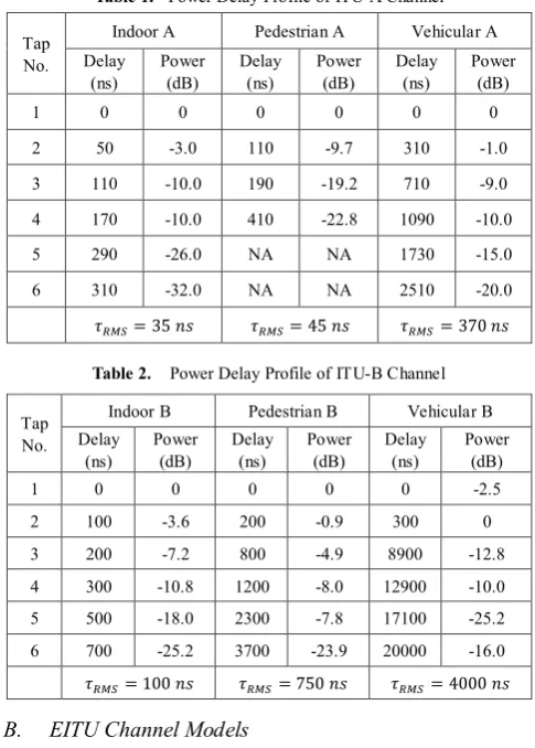
[image:3.595.309.554.155.507.2]The ITU channel models consist of two types of the channels. Table.1 and Table.2 show the PDPs and the characteristic of these channels. Theses Tables indicate the relative delay, the average power for the taps of the multi-path channel and the RMS delay spread based on the ITU recommendation.
Table 1. Power Delay Profile of ITU-A Channel
Tap No.
Indoor A Pedestrian A Vehicular A
Delay
(ns) Power (dB) Delay (ns) Power (dB) Delay (ns) Power (dB)
1 0 0 0 0 0 0
2 50 -3.0 110 -9.7 310 -1.0
3 110 -10.0 190 -19.2 710 -9.0
4 170 -10.0 410 -22.8 1090 -10.0
5 290 -26.0 NA NA 1730 -15.0
6 310 -32.0 NA NA 2510 -20.0
𝜏𝜏𝑅𝑅𝑂𝑂𝑅𝑅= 35 𝑛𝑛𝑛𝑛 𝜏𝜏𝑅𝑅𝑂𝑂𝑅𝑅= 45 𝑛𝑛𝑛𝑛 𝜏𝜏𝑅𝑅𝑂𝑂𝑅𝑅= 370 𝑛𝑛𝑛𝑛
Table 2. Power Delay Profile of ITU-B Channel
Tap No.
Indoor B Pedestrian B Vehicular B
Delay
(ns) Power (dB) Delay (ns) Power (dB) Delay (ns) Power (dB)
1 0 0 0 0 0 -2.5
2 100 -3.6 200 -0.9 300 0
3 200 -7.2 800 -4.9 8900 -12.8
4 300 -10.8 1200 -8.0 12900 -10.0
5 500 -18.0 2300 -7.8 17100 -25.2
6 700 -25.2 3700 -23.9 20000 -16.0
𝜏𝜏𝑅𝑅𝑂𝑂𝑅𝑅= 100 𝑛𝑛𝑛𝑛 𝜏𝜏𝑅𝑅𝑂𝑂𝑅𝑅= 750 𝑛𝑛𝑛𝑛 𝜏𝜏𝑅𝑅𝑂𝑂𝑅𝑅= 4000 𝑛𝑛𝑛𝑛
B. EITU Channel Models
The Extended ITU channel model for LTE was called Extended Pedestrian-A (EPA), Extended Vehicular-A (EVA), and Extended Typical Urban (ETU). Table.3 shows the PDPs and the characteristic of this channel. This Table indicates the channel models parameters such as the excess delay, the average power and the RMS delay spread.
C. 3GPP Channel Models
The 3GPP channel model consists of urban micro-cell and urban macro-cell channel model. Table.4 shows the tap delay, the average power and the RMS delay spread for these channel models.
Table 3. Power Delay Profile of EITU Channel
Tap No.
EPA EVA ETU
Delay
(ns) Power (dB) Delay (ns) Power (dB) Delay (ns) Power (dB)
1 0 0 0 0 0 -1.0
2 30 -1.0 30 -1.5 50 -1.0
3 70 -2.0 150 -1.4 120 -1.0
4 90 -3.0 310 -3.6 200 0.0
5 110 -8.0 370 -0.6 230 0.0
6 190 -17.2 710 -9.1 500 0.0
7 410 -20.8 1090 -7.0 1600 -3.0
8 NA NA 1730 -12 2300 -5.0
9 NA NA 2510 -16.9 5000 -7.0
𝜏𝜏𝑅𝑅𝑂𝑂𝑅𝑅= 45 𝑛𝑛𝑛𝑛 𝜏𝜏𝑅𝑅𝑂𝑂𝑅𝑅= 357 𝑛𝑛𝑛𝑛 𝜏𝜏𝑅𝑅𝑂𝑂𝑅𝑅= 991 𝑛𝑛𝑛𝑛
Table 4. Power Delay Profile of 3GPP Channel
Tap No.
Urban Macro Urban Micro
Delay (ns) Power (dB) Delay (ns) Power (dB)
1 0 0 0 0
2 0.36 -2.22 0.28 -1.27
3 0.25 -1.72 0.20 -2.72
4 1.04 -5.72 0.66 -4.30
5 2.7 -9.05 0.81 -6.01
6 4.59 -12.50 0.92 -8.43
𝜏𝜏𝑅𝑅𝑂𝑂𝑅𝑅= 850 𝑛𝑛𝑛𝑛 𝜏𝜏𝑅𝑅𝑂𝑂𝑅𝑅= 295 𝑛𝑛𝑛𝑛
5. Simulation Results and Discussion
The focus of this study is to give insight on the choice of an optimal CP length over different wireless channel models.
A. Performance Evaluation of SINR for Varying CP
Length
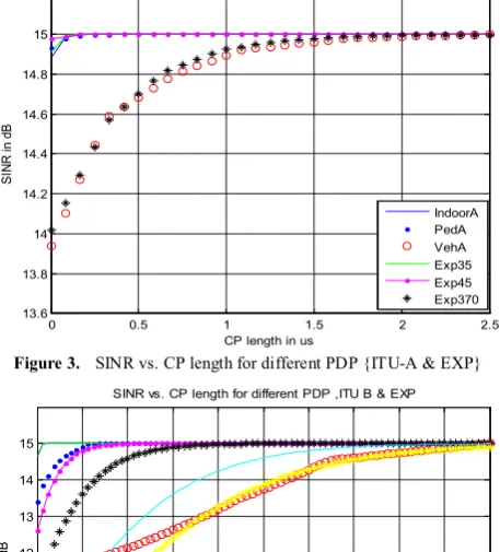
[image:3.595.55.298.345.684.2]the channel due to eliminating the multipath fading. Therefore; increasing the SNR will raise the SINR levels resulting in a larger CP length requirement. We can demonstrate from these figures that the maximum SINR occurs at the different optimal CP length due to the variable RMS delay spread. Therefore, the larger RMS delay spread required a larger CP length to get the maximum SINR and vice versa.
Figure 3. SINR vs. CP length for different PDP {ITU-A & EXP}
[image:4.595.63.292.163.748.2]Figure 4. SINR vs. CP length for different PDP {ITU-B & EXP}
Figure 5. SINR vs. CP length for different PDP {EITU & EXP}
Figure 6. SINR vs. CP length for different PDP {3GPP & EXP}
B. Effect of CP Length on OFDM System Spectral
Efficiency
A conducted study giving insight on the impact of the CP length on the capacity of a base-band synchronized OFDM system. The capacity is used to evaluate the system and it is measured in bits per second per hertz. This study indicates how the CP length affects Spectral Efficiency Loss (SEL) and Signal to Interference and Noise Ratio (SINR) where SINR is mapped to capacity through Shannon’s formula [14]. The optimum CP length maximizes the capacity for a given set of system parameters. The system parameters that will be considered in this section are Signal to Noise ratio (SNR) at the receiver side, OFDM useful symbol length and different channels with different PDPs.
As seen previously, maximizing SINR causes high BER at the receiver side, which requires a larger CP length, but utilizing a larger CP length extends the transmission time required. Therefore, an optimization of the SINR is required and can be obtained from Shannon’s capacity theorem. We used an approach similar to [14] where SINR is mapped to capacity in b/s/Hz through Shannon’s Capacity theorem. In doing this we accounted for a link adaptation loss ∝𝑙𝑙𝑙𝑙𝑠𝑠𝑠𝑠 and
a maximum bandwidth efficiency corresponding to 64QAM modulation. It follows that the capacity model over useful OFDM symbol length for the 𝑝𝑝𝑡𝑡ℎ channel profile is given by: C�Tg�= (1−SEL)∗min�log2�1 +αloss SINR�Tg��, 6� (5) Where SEL is the Spectral Efficiency Loss (CP length / Total OFDM symbol length) and ∝𝑙𝑙𝑙𝑙𝑠𝑠𝑠𝑠 is the degradation
factor which has a value of 0.4 for this study as it is used in [14].
1- Effect of SNR on the CP Length
Equation (2) shows that the SINR depends on the received SNR. The received SNR becomes equal to the SINR as the CP length exceeds the maximum excess delay spread of the channel impulse response as shown previously. Figs. 7 shows the influence of the received SNR on the CP length over Ped-B PDP. It can be observed that the effect of increasing the CP length at receiver is more pronounced at
0 0.5 1 1.5 2 2.5
13.6 13.8 14 14.2 14.4 14.6 14.8 15 15.2
CP length in us
SI
NR i
n d
B
SINR vs. CP length for different PDP ,ITU A & EXP
IndoorA PedA VehA Exp35 Exp45 Exp370
0 2 4 6 8 10 12 14 16 18 20
7 8 9 10 11 12 13 14 15
CP length in us
SI
NR i
n d
B
SINR vs. CP length for different PDP ,ITU B & EXP
IndoorB PedB VehB Exp100 Exp750 Exp1500 Exp3000 Exp4000
0 1 2 3 4 5 6 7 8 9 10
7 8 9 10 11 12 13 14 15
CP length in us
SI
NR i
n d
B
SINR vs. CP length for different PDP ,EITU & EXP
EVA EPA ETU Exp45 Exp357 Exp991 EXP1500
0 2 4 6 8 10 12 14 16 18 20
4 6 8 10 12 14
CP length in us
SI
NR i
n d
B
SINR vs. CP length for different PDP :(Urban ,EXP)
[image:4.595.64.293.190.443.2]high SNR, whereas at low SNR its effect is insignificant. I.e.
at 31 dB there is a difference of 1.5 bit/s/Hz in capacity for
[image:5.595.313.548.78.284.2]CP length varying between 0 and 1.6 µs, but at 1 dB the variation is about 0.1 bit/s/Hz in capacity for the same interval. Therefore; we can conclude that increasing the received SNR increases the required CP length, while a decrease in received SNR tolerates a lower CP requirement.
Figure 7. Capacity vs. CP length for different received SNR, PDP=Ped B
2- Effect of the Symbol Duration on the CP Length The effect of the useful symbol length (𝑇𝑇𝑢𝑢) on the CP
length over EPA PDP is studied in Fig. 8. It can be seen that the capacity of longer useful symbol length is minimally affected by CP length changes, but the capacity of shorter useful symbol length suffers more variation with changes in CP length. I.e. if CP =1.4 µs then with 𝑇𝑇𝑢𝑢= 160 µs the
capacity is decreased by 0.1 bit/s/Hz from the maximum achievable performance, while with 𝑇𝑇𝑢𝑢= 10 µs the loss
would be more than 0.7 bit/s/Hz. Therefore; the longer symbol length is preferable to shorter symbol length.
Figure 8. Capacity vs. CP length for different 𝑻𝑻𝒖𝒖 , PDP=EPA.
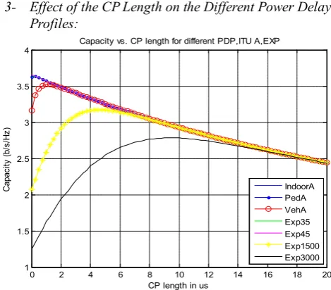
[image:5.595.60.294.168.344.2]3- Effect of the CP Length on the Different Power Delay Profiles:
Figure 9. Influence of the ITU-A PDP & EXP PDP on CP length.
Figure 10. Influence of the ITU-B PDP & EXP PDP on CP length.
Figure 11. Influence of the EITU PDP & EXP PDP on CP length
0 1 2 3 4 5 6 7 8 9 10
0 1 2 3 4 5 6
CP length in us
Capac
ity
(b/
s/
Hz
)
Capacity vs. CP length for different received SNR,PDP=PedB
1 dB 7 dB 11 dB 20 dB 31 dB
0 0.2 0.4 0.6 0.8 1 1.2 1.4 1.6 1.8 2
4.4 4.5 4.6 4.7 4.8 4.9 5 5.1 5.2 5.3 5.4
CP length in us
Capac
ity
(b/
s/
Hz
)
Capacity vs. CP length for different useful OFDM symbol lengths,PDP=EPA
10 mus 20 mus 40 mus 60 mus 80 mus 160 mus
0 2 4 6 8 10 12 14 16 18 20
1 1.5 2 2.5 3 3.5 4
CP length in us
Capac
ity
(b/
s/
Hz
)
Capacity vs. CP length for different PDP,ITU A,EXP
IndoorA PedA VehA Exp35 Exp45 Exp1500 Exp3000
0 2 4 6 8 10 12 14 16 18 20
0.5 1 1.5 2 2.5 3 3.5 4
CP length in us
Capac
ity
(b/
s/
Hz
)
Capacity vs. CP length for different PDP,ITU B & EXP
IndoorB PedB VehB Exp100 Exp750 Exp3000 Exp4000
0 2 4 6 8 10 12 14 16 18 20
0.5 1 1.5 2 2.5 3 3.5 4
CP length in us
Capac
ity
(b/
s/
Hz
)
Capacity vs. CP length for different PDP,EITU & EXP
[image:5.595.314.547.306.492.2] [image:5.595.60.294.514.688.2] [image:5.595.314.550.517.706.2]Figure 12. Influence of the ITU-A PDP & EXP PDP on CP length.
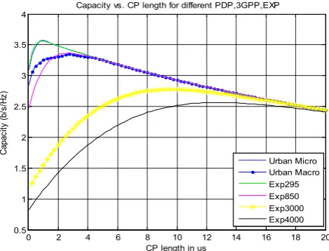
Figures 9, 10, 11 and 12 show the effect of varying the CP length on different channel PDPs. In these figures, the CP length varies from one PDP to another based on the RMS delay spread. Exponentially decaying PDPs are plotted with different RMS delay spread. It is noted that the optimal CP length for exponential decaying PDPs increases as the RMS delay spread is increased. When comparing the exponential decaying PDPs with standard PDPs with equal RMS delay spread, we will see that the optimal CP length can significantly vary from profile to profile. As can be seen in Fig.9 and Fig.10, the indoor channel has the smallest CP length while the vehicular channel has the largest CP length because the vehicular channel has a large delay spread. In Fig.11, the ETU PDP has larger CP length as compared to EPA PDP and EVA PDP, because the ETU PDP has a larger delay spread. In Fig.12, the macro-cell PDP required a larger CP length than micro-cell PDP, because the macro-cell has a larger delay spread. These figures indicate that the CP length increases as the RMS delay spread is increased. One of the methods used to estimate the optimal CP length is based on the RMS delay spread; according to this approach the CP length is estimated and it is given as: (CP=α*RMS) where α is the constant in the range between (2.5 to 3.5). This conforms the findings of a previous study by Arslan who found that the (CP=β*RMS)) where β is the constant in the range between (2 to 4) [15]. It can also be observed from these figures the estimated CP maximizes the system capacity, but increasing the CP length beyond this optimum CP length results in decreasing the system capacity.
C. Mathematical Relationship between the CP & the
RMS Delay Spread of the Channel
As we mentioned earlier the CP can be estimated based on the RMS delay spread of the channel. In this study the SINR is applied to the PDP and the CP is calculated based on the RMS delay spread. It is found that CP=α*RMS where α is the constant in the range between (2.5 to 3.5) optimizes the system’s performance. Fig 13, 14 and 15 show the
[image:6.595.59.294.76.255.2]mathematical relationship between the CP and the RMS delay spread of different multipath channel. It can be seen clearly from these figures that the CP length increases as the RMS delay spread of the channel is increased which indicates a linear relationship exists between them. Obviously the RMS delay spread is not fixed in the mobile wireless communication and its value changes depending on the terrain, clutter, antenna directivity and other factors related to propagation environment. The conventional OFDM system uses a fixed and large CP length which increases the overhead, but if one estimates the CP length based on the RMS delay spread the overhead will be reduced. Therefore; the CP length needs to be adjusted to the environment so that the mobile battery power and scarce spectrum can be conserved when the delay spread is small. Furthermore the system performance will be maintained by reducing the ISI and ICI when the delay spread is large. From these figures, it is evident that channels such as the Indoor A, B and EPA with small RMS delay spread require small CP length, whereas the channel such as the vehicular B and ETU channel with large RMS delay spread requires large CP length. It can also be seen the channel with exponentially decaying PDPs required a large CP length as RMS delay spread is increased.
Figure 13. CP lengths vs. RMS delay spread for ITU-A, & ITU-B
Figure 14. CP lengths vs. RMS delay spread for ITU-B, EITU & EXP
0 2 4 6 8 10 12 14 16 18 20
0.5 1 1.5 2 2.5 3 3.5 4
CP length in us
Capac
ity
(b/
s/
Hz
)
Capacity vs. CP length for different PDP,3GPP,EXP
Urban Micro Urban Macro Exp295 Exp850 Exp3000 Exp4000
0 0.5 1 1.5 2 2.5 3 3.5 4
x 10-6 -2
0 2 4 6 8 10 12 14
Trms of the channels
O
pt
im
um
C
P i
n m
ic
ro-sec
ond
InB
PeB
VeB
InA
PeA VeA
0 0.5 1 1.5 2 2.5 3 3.5 4
x 10-6 -2
0 2 4 6 8 10 12 14
Trms of the channels
O
pt
im
um
C
P i
n m
ic
ro-sec
ond
InB
PeB
VeB
E1500
E3000
E4000
EPA EVA
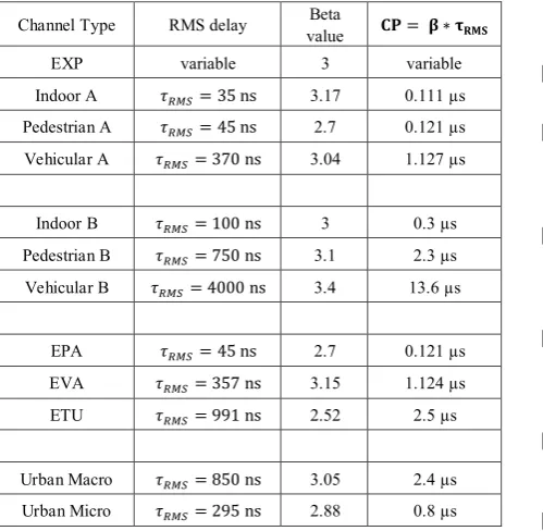
[image:6.595.314.549.374.536.2] [image:6.595.315.548.570.730.2]Figure 15. CP lengths vs. RMS delay spread for ITU-B, & 3GPP As aforementioned, the proposed CP model is estimated based on RMS delay spread, and it is found that CP=α*RMS represent a mathematical formula to calculate the estimated CP length over different wireless channel models. According to this approach, the Table. 5 shows the optimal parameters associated with this analysis to determine the optimal CP length over different multipath channels.
Table 5. The values of the CP length for different channel models
according to the RMS delay spread method.
Channel Type RMS delay value Beta 𝐂𝐂𝐂𝐂= 𝛃𝛃 ∗ 𝛕𝛕𝐑𝐑𝐑𝐑𝐑𝐑
EXP variable 3 variable
Indoor A 𝜏𝜏𝑅𝑅𝑂𝑂𝑅𝑅= 35 ns 3.17 0.111 µs Pedestrian A 𝜏𝜏𝑅𝑅𝑂𝑂𝑅𝑅= 45 ns 2.7 0.121 µs Vehicular A 𝜏𝜏𝑅𝑅𝑂𝑂𝑅𝑅= 370 ns 3.04 1.127 µs
Indoor B 𝜏𝜏𝑅𝑅𝑂𝑂𝑅𝑅= 100 ns 3 0.3 µs
Pedestrian B 𝜏𝜏𝑅𝑅𝑂𝑂𝑅𝑅= 750 ns 3.1 2.3 µs Vehicular B 𝜏𝜏𝑅𝑅𝑂𝑂𝑅𝑅= 4000 ns 3.4 13.6 µs
EPA 𝜏𝜏𝑅𝑅𝑂𝑂𝑅𝑅= 45 ns 2.7 0.121 µs
EVA 𝜏𝜏𝑅𝑅𝑂𝑂𝑅𝑅= 357 ns 3.15 1.124 µs
ETU 𝜏𝜏𝑅𝑅𝑂𝑂𝑅𝑅= 991 ns 2.52 2.5 µs
Urban Macro 𝜏𝜏𝑅𝑅𝑂𝑂𝑅𝑅= 850 ns 3.05 2.4 µs Urban Micro 𝜏𝜏𝑅𝑅𝑂𝑂𝑅𝑅= 295 ns 2.88 0.8 µs
6. Conclusions
An adaptive OFDM system with variable CP length over different channel models with different PDPs was described in this paper. We presented a method to estimate the CP length based on the RMS delay spread of the channel. According to this approach, the CP length is chosen to improve the system performance and to optimize the system capacity by mitigating both ISI and ICI. We demonstrated
that the optimal CP length correlates very well with the RMS delay spread of the channel. Therefore, the choice of variable CP length is preferable to large and fixed CP length because it offers improved spectral efficiency. Furthermore, these simulation results showed that increasing the CP length beyond the optimum length does not result in further improvement of the system capacity and the system performance.
Finally, it may be concluded that the CP length is an essential aspect of the OFDM system. When the CP selected optimally based on the channel parameters, the overall system performance is improved. This is accomplished through effectively mitigating the dominant problems (ISI and ICI) in the OFDM system.
REFERENCES
[1] Kaur, Sandeep, and Gurpreet Bharti. "Orthogonal Frequency
Division Multiplexing in Wireless Communication Systems:
A Review."International Journal of Advanced Research in
Computer Engineering & Technology (IJARCET)1, no. 3
(2012): pp-125.
[2] Marchetti, Nicola, Muhammad Imadur Rahman, Sanjay
Kumar, and Ramjee Prasad. "OFDM: Principles and
Challenges." InNew Directions in Wireless Communications
Research, pp. 29-62. Springer US, 2009.
[3] Prasad, Ramjee.OFDM for wireless communications
systems. Artech House, 2004.
[4] J. Li and M. Kavehrad, “Effects of time selective multipath
fading on OFDM systems for broadband mobile applications,” IEEE Commun. Lett., vol. 3, no. 12, pp. 332-334, 1999.
[5] Y. Zhang and H. Liu, “Impact of time selective fading on the
performance of quasi-orthogonal space-time coded OFDM systems,” IEEE Trans. Commun., vol. 54, no. 2, pp. 251-260, 2006.
[6] Shah, D. C., B. U. Rindhe, and S. K. Narayankhedkar.
"Effects of cyclic prefix on OFDM system." InProceedings
of the International Conference and Workshop on Emerging Trends in Technology, pp. 420-424. ACM, 2010.
[7] Ness, Reto, Jean-Paul Linnartz, Liesbet Van der Perre, and
Marc Engels. "The OFDM Principle." InWireless OFDM
Systems, pp. 33-51. Springer US, 2002.
[8] Payaswini P, and Manjaiah D.H "Analysis of Effect of Cyclic
Prefix on Data Rates in OFDM Modulation
Techniques"International Journal of Advanced Research
Computer and Mathemmatical Sciences (IJARCMS), Vol.
3 ,2012, pp-465-470.
[9] Das, Suvra Sekhar, Frank HP Fitzek, E. D. Carvalho, and
Ramjee Prasad. "Variable guard interval orthogonal frequency division multiplexing in presence of carrier
frequency offset." InGlobal Telecommunications
Conference, 2005. GLOBECOM'05. IEEE, vol. 5, pp. 5-pp. IEEE, 2005.
[10] Ghosh, Sayani. "Performance Study of WiMAX for Different
0 0.5 1 1.5 2 2.5 3 3.5 4
x 10-6 -2
0 2 4 6 8 10 12 14
Trms of the channels
O
pt
im
um
C
P i
n m
ic
ro-sec
ond
InB
PeB
VeB
[image:7.595.62.312.387.631.2]QoS Parameters with Varying Cyclic Prefix." PhD diss., JADAVPUR UNIVERSITY KOLKATA, 2011.
[11] Zhang, Zhao-yang, and Li-feng Lai. "A novel OFDM
transmission scheme with length-adaptive Cyclic
Prefix."Journal of Zhejiang University SCIENCE5, no. 11
(2004): 1336-1342.
[12] Lim, Chiwoo, Youngbin Chang, Jaeweon Cho, Panyuh Joo,
and Hyeonwoo Lee. "Novel OFDM transmission scheme to overcome caused by multipath delay longer than cyclic
prefix." InVehicular Technology Conference, 2005. VTC
2005-Spring. 2005 IEEE 61st, vol. 3, pp. 1763-1767. IEEE,
2005.
[13] Nolan, Keith E. "Reconfigurable OFDM systems." PhD diss.,
Trinity College Dublin., 2005.
[14] Batariere, Mickael, Kevin Baum, and Thomas P. Krauss.
"Cyclic prefix length analysis for 4G OFDM systems."
InVehicular Technology Conference, 2004. VTC2004-Fall.
2004 IEEE 60th, vol. 1, pp. 543-547. IEEE, 2004.
[15] Arslan, Hüseyin, and Tevfik Yucek. "Delay spread estimation
for wireless communication systems." In Computers and