Point-to-Point Trajectory Tracking with
Two-Degree-of-Freedom Robust Control for a Non-minimum Phase
Electro-hydraulic System
Rozaimi Ghazali
Yahaya Md Sam, Mohd Fua’ad Rahmat and Zulfatman
Department of Mechatronic and Robotic Engineering Faculty of Electrical and Electronic Engineering
Department of Control and Instrumentation Engineering Faculty of Electrical Engineering
Universiti Tun Hussein Onn Malaysia Universiti Teknologi Malaysia 86400, Batu Pahat, Johor, Malaysia 81310,Skudai, Johor, Malaysia
[email protected] [email protected]
Abstract - Electro-hydraulic actuator (EHA) system inherently suffers from uncertainties, nonlinearities and time-varying in its model parameters which makes the modeling and controller designs are more complicated. The main objective of this paper is to perform a robust control design using discrete-time sliding mode control (DSMC) with two-degree-of-freedom (2-DOF) control strategy. The proposed controller consists of feedback and feedforward combination which capable to reduce phase lag and steady state error during the trajectory tracking of EHA system. The feedforward controller is developed by implementing the zero phase error tracking control (ZPETC) technique which the main difficulty arises from the nonminimum phase system with no stable inverse. A point-to-point trajectory is used in the experimental works to evaluate the performance of the DSMC. Experimental results reveal that the DMSC with 2-DOF control structure is highly robust and capable to deal with the uncertainties and disturbances occur during the position tracking control for different point of trajectories. It is also shows that the proposed controller can achieve better tracking performance as compared to conventional LQR and PID controller.
Keywords - Electro-hydraulic Actuator System; Discrete Sliding Mode Control; Point-to-Point Trajectory Tracking Control; Two-degree-of-freedom Control Structure
I. INTRODUCTION
Electro-hydraulic actuator (EHA) system emerge in fluid power technology is greatly developed from the beginning of the twentieth century where the works was first introduced by French physicist Braise Pascal in 1640s. The works concerning the principle of differential pressure turn this actuator becomes more crucial nowadays. There are many unique elements and advantages of EHA system over rival actuators such as pneumatic and electrical motor in the market these days. The main advantages of fluid power, which is led to its prominent feature, is the good ratio between forces delivered by the actuator over the weight and its size [1]. The lighter and smaller compact structure in EHA system makes this actuator very suitable to use especially in mobile industrial applications. Moreover, the combination between electrical and hydraulic devices also rendered EHA system be
more flexible in implementing to real application with advanced control strategies.
EHA system has become progressively popular in various types of engineering equipment and by utilizing it advantageous, different applications such as aircrafts [2], manufacturing machines [3], fatigue testing [4], hydraulic excavator [5], sheet metal forming process [6] and automotive applications [7] established that the actuator system can be more well-known and crucial nowadays. However, the EHA system is known as a complicated system which suffers from uncertainties, nonlinearities and disturbances. These inconveniences may lead to degradation of control performance in trajectory tracking of the EHA system.
Nonlinear flow and pressure characteristics, actuator friction, fluid compressibility and leakages are identified as the significant sources of nonlinearity exist in the EHA system [8]. Recent works in [9] established mathematical model of the EHA system by including the effect of compressibility, external leakage in actuator and internal leakage in the servo valve. Most of flow valves also suffer from hard nonlinearities such as dead-zone due to asymmetric overlap in the spool valve design [10, 11]. Besides, the friction phenomena that generally affect the tracking performance are often considered as a nonlinear model in developing the dynamics equation of EHA system [12]. Therefore, a feedback control strategy is always required in designing the high performance trajectory tracking and positioning of EHA system.
Various types of feedback controller ranging from linear to nonlinear type are widely implemented and published among academia and researchers for trajectory tracking control of EHA system. The increasing numbers of works dealing with EHA system over the past decades involved a linear control, intelligent control and nonlinear control approaches such as neural network (NN) [10], self-tuning Fuzzy-PID [13,14], model reference adaptive control (MRAC) [15,16], generalized predictive control (GPC) [17] and sliding mode control (SMC) [18]. There are much works in designing SMC for EHA system previously based on continuous-time [19-22]. SMC is recognized as a one of the most potential approach in nonlinear control field and has been proved to the problem of maintaining the stability for controlling many classes of model that are subjected to parameter variations and Proceedings of the 10th
external disturbances [23]. However, not much study in utilizing SMC in discrete-time for trajectory tracking of an EHA system. As most controllers are now implemented digitally, it is more suitable to design the SMC based on a discrete-time.
Trajectory tracking control with the discrete sliding mode control (DSMC) is typically necessary in minimizing the tracking error for the system subjected to uncertainties and disturbances. The controller design is then can be improved with a robust control where a feedforward controller is introduced in two-degree-of-freedom (2-DOF) structure to eliminate the phase error that always emerges during the trajectory tracking control [24]. The main objective in that control scheme is to drive the hydraulic actuator to follow closely the desired trajectory and minimizing the phase lag that regularly caused by feedback loop in closed loop system. However, the feedforward controller is unable to design if the class of system with disturbance considered is a non-minimum phase which presents zeroes outside the unit circle. For non-minimum phase system, the main difficulty arises from these systems which have no stable inverse. The zeros presented outside the unit circle will be unstable poles during the inversion process.
In this paper, the tracking control performance of nonminimum phase EHA system is evaluated by using DSMC. A linear model consists of servo valve and hydraulic actuator is determined first using the system identification technique through experimental works. Based on the EHA model, the DSMC control law based on reaching law concept is developed and a feedforward controller in 2-DOF control structure is designed. Lastly, an experimental study is implemented with the designed controller for a point-to-point type of trajectory and comparison with the conventional Linear-Quadratic-Regulator (LQR) and Proportional-Integral-Derivative (PID) controller is presented.
[image:2.612.60.275.507.618.2]II.MODELING OF EHASYSTEM
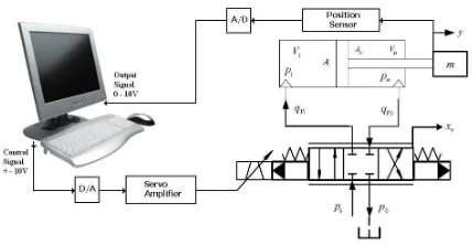
Fig. 1 EHA system schematic diagram
A complete mathematical model with internal leakage, actuator leakage and friction model have been discussed lately in [9] with intelligent control strategy. However, the physical models derived in that simulation study are highly complex and difficult to utilize in some of the control designs
especially in industrial field. Most of the parameters involved in that mathematical model are usually not available in the manufacturer’s datasheet and vastly vary with time due to its nonlinearity. Besides, the parameters are affected by the hydraulic oil temperature, supply pressure changes and aging.
A mathematical model of an EHA system in Fig.1 can be developed by neglecting these nonlinearities such as internal or external leakage and dynamics of the valve as explained in [10]. In servo valve design, the dynamics of the valve can be approximated as a single gain where the spool valve structure is assumed as critical-center and symmetrical. The equation relates the input signal u (either voltage or current), servo valve gain Kv and the spool valve position xv is given by
x
v=
K
vu
(1)Thus, the dynamics of the EHA system for the total oil flow
QL are derived from a Taylor series linearization by the
following equation.
Q
L=
K
qx
v−
K
CP
L (2)where Kq = flow-gain coefficient and Kc = flow-pressure coefficient
Defining the load pressure, PL as the pressure across the
actuator piston, its derivative is given by the total oil load flow
QL through the actuator divided by the fluid capacitance as
given by
)
(
4
y
A
P
C
Q
V
P
L tp L pt e
L
=
β
−
−
(3)where e is the bulk modulus, Vt is the total compressed oil
volume, Ctp is the total leakage coefficient, Ap is the surface
area of the piston and y is the position of the piston.
The force of the actuator Fa that generates from a total
mass Mt attached to the end of the piston can be determined as
y
M
P
A
F
a=
p L=
t (4) Substituting (2) and (3) into the derivative of (4) and taking a Laplace transform that yields)
2
(
)
(
)
(
2 2
2
n n n
s
s
s
K
s
U
s
Y
ω
ξω
ω
+
+
=
(5)where,
,
p v q
A K K K =
t t
e p n
M V
A
β
ω
= 4 andp tp c t
t e
A C K V
M
2
) (
4
+ =
β
ξ
Open loop transfer function of the EHA system relates between the control signal from the computer (controller) and position of the hydraulic actuator. The corresponding discrete-time model follows by transforming the continuous-discrete-time model in (5) with zero-order-hold as in (6).
2 3
2 1 3
3 2 2 1
)
(
)
(
)
(
a
z
a
z
a
z
b
z
b
z
b
k
u
k
y
z
G
+
+
+
+
+
=
=
(6)researchers who used that linear model in either continuous-time or discrete-continuous-time in their proposed control strategy. Most of the modeling approaches for discrete-time model that have been implemented in previous researches are developed from first principle or physical laws. Although the importance of physical modeling is always considered in the controller design, but in real implementation, validation of the physical plant model is necessary in optimizing the use of controller that commonly designs via computer simulation. Furthermore, any changes in the EHA system’s parameter may reduce the controller performance and the desired specification possibly not achieved. Therefore, system identification with online estimation technique is always performed as an adaptive mechanism integrating with other control design [25]. The discrete-time transfer function in (6) can be represented in state-space control canonical form.
x
(
k
+
1
)
=
Φ
x
(
k
)
+
Γ
u
(
k
)
(7)y
(
k
)
=
Ψ
x
(
k
)
(8) where»
»
»
¼
º
«
«
«
¬
ª
−
−
−
=
Φ
0
1
0
0
0
1
3 2
1
a
a
a
,
Γ
=
[
1
0
0
]
T and[
b
1b
2b
3]
=
Ψ
.
From the state space model in (7) and (8), the discrete-time transfer function can be derived as
)
(
)
(
)
(
)
(
1z
G
zI
k
u
k
y
=
Γ
Φ
−
Ψ
=
−(9)
Since the 2-DOF controller design is based on cancellation of all of the poles and well-damped zeros of feedback loop systems, the plant dynamics must be known in advance. A discrete-time model is determined experimentally using system identification technique from real plant of EHA system. A third order system is found to be adequate to represent the EHA system and being used in the control analysis [26-27]. The percentage of best fit for a third order model is 95.48% while the final prediction error is 0.0228. The discrete-time transfer function obtained from the identification is represented in (10).
1
.
887
1
.
056
0
.
1695
0.2738
0.3836
0.03093
)
(
)
(
)
(
3 22
−
+
−
−
+
−
=
=
z
z
z
z
z
k
u
k
y
z
G
(10)
III. DISCRETE SLIDING MODE CONTROL
Fundamental idea of the perfect tracking control strategy in 2-DOF structure is to achieve the transfer function from the desired trajectory to the output of the systems to become unity [28]. With that, the feedforward controller can be designed by the inverse of closed loop system transfer function and the phase error can be eliminated in the tracking control system. A robust control such as SMC is needed in designing the feedback controller to obtain a promising performance in the trajectory tracking control. The controller design in SMC is quite unique as compared to any other controller design methods since the performance of the controller depends on
the design of the sliding surface and not the state tracking directly. The idea of SMC strategy is to force the trajectory of the states towards the sliding surface and once reached, the states are forced to remain on that surface.
SMC is a type of variable structure control (VSC) developed in the early of 60’s in Russia [23]. This robust control technique is originally established in continuous-time. Various researchers have utilized the SMC schemes to control a number of nonlinear and uncertain systems due to its inherent insensitivity property to parameter variations and external disturbances. A research in developing SMC in discrete-time only starts in the late of 80’s. It is established that the most crucial step in designing the SMC either in continuous-time or discrete-time is the construction of the sliding surface which is expected to response the desired control specifications and performances. The sliding surface can be expressed as in (11).
s
(
k
)
=
C
smcx
(
k
)
(11) The reachability condition to ensure the stability in discrete-time is represented by
s
(
k
+
1
)
<
s
(
k
)
(12)Different from the DSMC design based on equivalent technique, the concept of reaching law can be used to design the DSMC control law and it is proven to be stable by fulfilled the reachability condition [24]. The reaching law in discrete-time is used in the controller design is
s
(
k
+
1
)
=
(
1
−
qT
s)
s
(
k
)
−
η
T
ssign
(
s
)
(13) withη
>0 and0
<
(
1
−
qT
s)
<
1
The control law can be designed for the nominal plant model in (7) with uncertainties and disturbances where the uncertain and disturbed plant can be modeled as
x
(
k
+
1
)
=
(
Φ
+
ΔΦ
)
x
(
k
)
+
Γ
u
(
k
)
+
Pf
(
k
)
(14) Designing the DSMC control law with reaching law givesu
(
k
)
=
−
(
C
smcΓ
)
1[
C
smcΦ
−
(
1
−
qT
s)
C
smc]
x
(
k
))
−
)
(
(
)
(
C
smcΓ
−1η
T
ssign
s
k
−
)]
(
)
(
[
)
(
C
1C
x
k
C
Pf
k
smc smc
smc
Γ
ΔΦ
+
−
−(15) The developed control law is redesigned due to the unknown terms
ΔΦ
andf
(
k
)
which are usually unknown. The assumption where the lower and upper bounds of) ( )
(k C Pf k x
CsmcΔΦ + smc is assigned by the following
condition
−
L
dT
s<
C
smcΔΦ
x
(
k
)
+
C
smcPf
(
k
)
<
L
dT
s (16) whereL
d is the lumped uncertainties and disturbances boundary in the system. The SMC control law is then modified as (17).
u
(
k
)
(
C
)
1[
C
(
1
qT
)
C
]
x
(
k
)
smc s smc
smc
Γ
Φ
−
−
−
=
−))
(
(
)
(
C
smc 1η
T
ssign
s
k
−
Γ
−
))
(
(
)
(
C
1L
T
sign
s
k
s d smc
−
Γ
−
(17)The control law in (16) only guarantees that
0
)]
(
)
1
(
)[
(
k
s
k
+
−
s
k
<
quasi-sliding mode [25]. It is necessary that the control law to guarantees a sliding mode condition where
)
1
(
2
s s s dqT
T
T
L
−
<
η
withη
>
0
,L
d>
0
(18) The resulting SMC control for the bounded uncertainties can be represented as (19).
u
(
k
)
=
−
K
smcx
(
k
)
−
K
swsign
(
s
(
k
))
(19) whereK
smc=
(
C
smcΓ
)
1[
C
smcΦ
−
(
1
−
qT
s)
C
smc]
− and
s sw smc s d smc
sw C L T C T
K =( Γ)−1(
η
+ ) =( Γ)−1ρ
.The selection of the parameter
ρ
sw=η
+Ldin the switching control law is usually a trade-off between width of the quasi sliding mode band and robust performance of the system under model uncertainties and disturbances [24]. Therefore, the closed loop system inside the sliding mode band which is without the uncertainties and disturbances can be represented as (20).=Ψ −Φ −1Γ
) (
)
(z zI cl
T (20)
where ] ) 1 ( [ )
( smc 1 smc s smc smc
cl =Φ−ΓK =Φ−Γ C Γ C Φ− −qT C
Φ −
Most of tracking control system with DSMC is purposely for minimizing gain error from the output to the desired trajectory. However, the phase error in the trajectory tracking is always neglected in that control scheme. Thus, the trajectory tracking error minimization can be achieved by introducing a feedforward controller to eliminate the zeros and poles in the closed loop system [28]. The main objective in that control scheme is to drive the actuator to follow perfectly the desired trajectory and minimizing the phase lag that regularly caused by feedback loop in closed loop system. For minimum phase model, the perfect tracking control structure can be designed by direct inverse of the closed loop system with DSMC in (20) to achieve a feedforward controller. The feedforward controller is then can be represented by (21).
1 1 1
] ) ( [ )] ( [ )
( = − = Ψ −Φcl − Γ − ff z T z zI
G (21)
It can be observed from the closed-loop transfer function, the numerator which represents the zeroes in the system is dominated by the open-loop system that caused a non-minimum phase problem. The problem of inversion is occurred when the Gcl(z) have zeros outside the unit circle where the non-minimum phase of the open-loop EHA system have influenced to the closed loop system dynamics. Direct inverse of the Gcl(z) will caused unstable condition in Gff(z). Therefore, method in [28] will be used in developing the feedforward controller to avoid the instability problem.
IV. FEEDFORWARD CONTROLLER DESIGN
Since the direct inverse of the closed loop transfer function is unfeasible, the approximation of the feedforward controller can be implemented to represent the inverse of closed loop system and cancelled the poles and zeros. The direct inversion of closed loop system can be represented as (22).
)
(
)
(
)]
(
[
)
(
1z
N
z
D
z
G
z
G
cl cl clff
=
=
−
0.2738
0.3836
0.03093
1404
.
0
9009
.
0
7022
.
1
2 2 3−
+
−
−
+
−
=
z
z
z
z
z
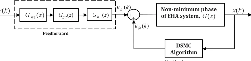
(22)The block diagram as shown in Fig. 2 described the approximation of feed-forward control design for nonminimum phase systems using ZPETC strategy. The proposed method can be divided into three blocks which are gain compensation filter, phase compensation filter and stable inverse. From (22), one of the poles in the feed-forward controller is outside in the unit circle. In the feed-forward design, equation in (22) can be represented in delay form.
3 2 1 3 2 1 1
0.2738
0.3836
0.03093
1404
.
0
9009
.
0
7022
.
1
1
)
(
− − − − − − −−
+
−
−
+
−
=
z
z
z
z
z
z
z
G
ff (23)The numerator of the closed-loop systems can be factorized in the feed-forward controller,
)
(
)
(
)
(
)
(
1 1 1 1 − − − + − −=
z
N
z
N
z
D
z
G
cl cl cl ff)
654
.
11
1
)(
76
.
0
1
(
0309
.
0
1404
.
0
9009
.
0
7022
.
1
1
1 1 1 3 2 1 − − − − − −−
−
−
−
+
−
=
z
z
z
z
z
z
(24) where)
76
.
0
1
(
0309
.
0
)
(
−1 −1 −1+
z
=
−
z
−
z
N
cl 1 1654
.
11
1
)
(
− − −=
−
z
z
N
clBased on the proposed method, stable inverse can be stated as following equation;
)
(
)
(
)
(
1 1 11 + −
− −
=
z
N
z
D
z
G
cl cl ff0.0309 (1 0.76 ) 1350 . 0 2405 . 0 6798 . 0 1 1 1 3 2 1 − − − − − − − + − − = z z z z z (25)
In advance form, the phase compensation filter can be described as;
G
2(
z
)
z
N
cl(
z
)
z
(
1
11
.
654
z
)
dff
=
=
−
−
(26) where d=1 and the gain compensation filter is
Fig. 2 Two-degree-of-freedom control structure with DSMC
[image:5.612.52.293.201.397.2]V. RESULTS AND DISCUSSION
Fig. 3 Experimental workbench of EHA system
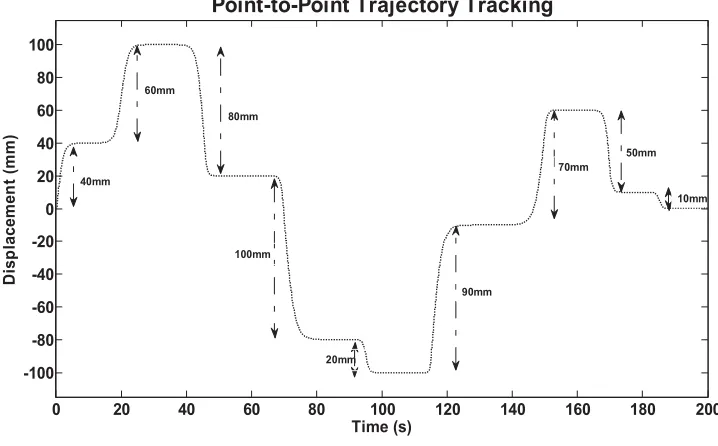
In the experimental study, point-to-point trajectory tracking performance of the proposed controller scheme is evaluated. The experimental design for EHA system is composed of a single-rod and double acting hydraulic cylinder, which is driven by a direct servo valve Bosch Rexroth 4WREE6, 40lpm flow rate at 80 bar. The dimensions of hydraulic cylinder are 63/30/300 (mm). Piston position is measured by using 300mm draw wire sensor. The control and associated data acquisition is realized using National Instruments Data Acquisition Card (DAQ).
Fig. 2 depicts the complete test bed of the EHA system. The sampling time is set at 5 milliseconds which caused a nonminimum phase model where the inverse of the closed loop system with DSMC can be achieved with ZPETC to perform a perfect tracking controller design. Point-to-point trajectory as illustrated in Fig. 3 is implemented as a desired position for the EHA system. This trajectory consists of different desired point over 50% total stroke of the hydraulic actuator. This trajectory tracking control is conducted for 200 seconds of experiment. The LQR and PID controller are also implemented in this experimental study. The LQR controller is constructed in 2-DOF control structure similar with the proposed controller while the PID control is designed with
conventional feedback structure. For practical comparison, the DSMC parameters are determined based on the closed loop poles as given by the LQR controller. The PID controller is tuned by using the Ziegler-Nichols technique. All the parameters of developed controllers are tabulated in Table I.
TABLE I CONTROLLER PARAMETERS Controller Parameter Value
DSMC
q 147.0254
sw
ρ 200
c1 1.0000
c2 -1.0082
c3 0.3284
LQR
k1 0.6140
k2 -0.4611
k3 0.0826
PID
Kp 1.8
Ki 0.03
Kd 0.16
From the experimental results, it shows that the tracking performance for both DSMC and LQR in Fig.4 is improved with the 2-DOF controller design where the piston position can track the point-to-point trajectory quite well as compared with conventional PID controller. It can be seen that the PID controller suffers due to phase lag during the tracking process. The tracking error as illustrated in Fig. 5 shows that DSMC and LQR result small error while the PID controller has shown significant tracking error. It is shows that DSMC with 2-DOF control strategy is very sensitive towards any changes in the system parameters. DMSC also is found to be capable to handle dead-band nonlinearity which occurs due to Coulomb friction and overlap of valve ports in the EHA system. The root-mean-square-error (RMSE) of the tracking error for 100 seconds of tracking control as tabulated in Table I described that DSMC perform better tracking performance as compared with LQR and PID controller.
) ( 2z Gff
Non-minimum phase
of EHA system,
G
(
z
)
DSMC Algorithm
)
(
1
z
G
ff Gff3(z)+ +
) (k ufb
) (k uff
)
(
k
x
)
(
k
r
Feedforward
0 20 40 60 80 100 120 140 160 180 200 -100
-80 -60 -40 -20 0 20 40 60 80 100
Point-to-Point Trajectory Tracking
Time (s)
D
is
p
lacem
en
t (
m
m
)
40mm 60mm
80mm
100mm
20mm
70mm
90mm
50mm
[image:6.612.122.481.61.284.2]10mm
Fig. 4 Point-to-point trajectory
0 20 40 60 80 100 120 140 160 180 200
-10 -5 0 5 10
Point-to-Point Trajectory Tracking Error
Time (s)
Di
spl
ace
men
t E
rr
o
r(
mm)
[image:6.612.120.481.65.532.2]SMC LQR PID
Fig. 5 Trajectory tracking error
The results of trajectory tracking error are concurrently presented in Fig. 4 for the DSMC, LQR and PID controllers. From the smooth step input trajectory of different point, the results obtained with DSMC controller is better as compared to LQR and PID controllers where the proposed controller produced more accurate results in order to reach the desired trajectory. Trajectory tracking error as shown in Fig. 4 described the accuracy of the proposed controller and the steady state values for every point during the tracking process are tabulated in Table II.
0 20 40 60 80 100 120 140 160 180 200 -10
-8 -6 -4 -2 0 2 4 6 8 10
Control Signal
Time (s)
Vo
lt
ag
e (
V
)
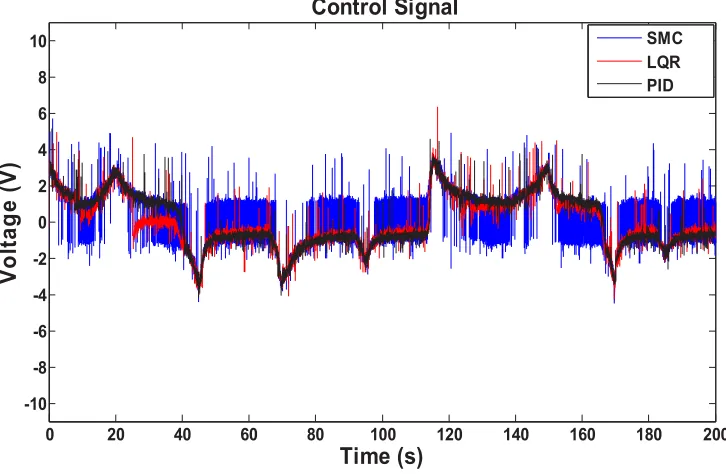
[image:7.612.122.485.61.298.2]SMC LQR PID
Fig. 6 Control signal
TABLE II
STEADY STATE ERROR ANALYSIS
Control
Technique DSMC LQR PID
(1st point)
40mm -0.0544 -0.3076 -0.4147 (2nd point)
60mm 0.0025 -0.0949 -0.2897 (3rd point)
80mm 0.0040 0.1988 0.4130
(4th point)
100mm -0.0250 0.2574 0.1250 (5th point)
20mm -0.0008 0.2524 0.0966 (6th point)
90mm 0.0134 -0.3372 -0.7463 (7th point)
70mm -0.0180 -0.3103 -0.2810 (8th point)
50mm 0.0121 0.2264 0.6549
(9th point)
10mm 0.0097 0.1460 0.3408
Root-mean-square-error (RMSE) for 200 seconds of experiment is determined and tabulated in Table III. Based on the error analyses, control efforts and observation on the tracking performance, the DSMC provides more convinient and better performance in trajectory tracking control and ensured that the control system in under stable condition. However, the RMSE for DSMC did not show any significant improvement as compared with LQR strategy. It is found there are small variations in the system’s parameters which represents the uncertainties and disturbances due the 200 seconds of experiments. Thus, in order to show a significant
robustness of the proposed controller, a robustness test can be conducted by varying the supply pressure or load in the EHA system. However, in the point-to-point trajectory control, the proposed DSMC still outperforms the LQR and PID in tracking the desired path precisely and with high accuracy.
TABLE III
ROOT-MEAN-SQUARE-ERROR FOR 200 SECONDS OF EXPERIMENT
Controller DSMC LQR PID
RMSE 0.2224 0.4495 0.6596
VI. CONCLUSION
In this study, the performance of DSMC in 2-DOF control structure is evaluated through experimental study for a point-to-point trajectory tracking control. Theoretical analysis is developed in DSMC to ensure that the system is under stable condition and its parameters are determined based on the desired closed loop response. The experimental results show that the DSMC provides better performance in tracking accuracy and is compared to the LQR and PID controller. As conclusion, the robustness of DSMC is guaranteed for a system which is subjected with uncertainties and disturbances.
ACKNOWLEDGMENT
The authors would like to thank Universiti Teknologi Malaysia (UTM) for the Research University Grant Vot 04J48 and Ministry of Science, Technology and Innovation (MOSTI) Malaysia for their support.
[image:7.612.77.266.342.575.2][1] H. E. Merrit, Hydraulic Control Systems, John Wiley & Sons, Inc., New York, 1967.
[2] M. Karpenko and N. Sepehri, “Hardware-in-the-loop simulator for research on fault tolerant control of electrohydraulic actuators in a flight control application”, Mechatronics, vol.19, pp.1067-1077, 2009. [3] J. Pluta, “Hydraulic press with LS system for modelling of Plastic
working operations”, Acta Montanistica Slovaca, vol.13, pp.152-157, 2008.
[4] J. Ruan, X. Pei and F.M. Zhu, “Identification and modeling of electrohydraulic force control of the material test system (MTS)”,
Journal of Physics: Conference Series, vol.48, pp.1322-1326, 2006. [5] M. H. Chiang and C. C. Huang, “Experimental implementation of
complex path tracking control for large robotic hydraulic excavators”,
International Journal of Advanced Manufacturing Technology, vol.23, pp.126-132, 2004.
[6] S. W. Lo and T. C. Yang, “Closed-loop control of the blank holding force in sheet metal forming with a new embedded-type displacement sensor”, International Journal of Advanced Manufacturing Technology, vol.24, pp.553-559, 2004.
[7] Y. M. Sam, J. H. S. Osman and M.R.A. Ghani, “A class of proportional-integral sliding mode control with application to active suspension system”, System and Control Letters, vol.51, pp.217-223, 2004.
[8] M. Jelali and A. Kroll, Hydraulic Servo-Systems: Modelling, Identification and Control, Springer, 2003.
[9] M. Kalyoncu and M. Haydim, “Mathematical modelling and fuzzy logic based position control of an electrohydraulic servosystem with internal leakage”, Mechatronics, vol.19, pp.847-858, 2009.
[10] T. Knohl and H. Unbehauen, “Adaptive position control of electrohydraulic servo systems using ANN”, Mechatronics, vol.10, pp.127-143, 2000.
[11] W. M. Bessa, M. S. Dutra and E. Kreuzer, “Sliding mode control with adaptive fuzzy dead-zone compensation of an electro-hydraulic servo-system”, Journal of Intelligent and Robotic Systems, vol.58, pp.3-16, 2010.
[12] M. Mihajlov, V. Nikolic and D. Antic, “Position control of an electro-hydraulic servo system using sliding mode control enhanced by fuzzy PI controller”, Facta Universitatis, Series: Mechanical Engineering, vol.1, no.9, pp.1217-1230, 2002.
[13] Zulfatman and M.F. Rahmat, “Application of self-tuning Fuzzy PID controller on industrial hydraulic actuator using system identification approach”, International Journal on Smart Sensing and Intelligent Systems, vol.2, no.2, pp.246-261, 2009.
[14] S. Cetin and A.V. Akkaya, “Simulation and hydbrid fuzzy-PID control for positioning of a hydraulic system”, Nonlinear Dynamics, vol.61, no.3, pp.465-476, 2010.
[15] K. Ziaei and N. Sepehri, “Design of a nonlinear adaptive controller for an electrohydraulic actuator”, Journal of Dynamic Systems, Measurement and Control, vol.123, pp.449-456, 2001.
[16] A. Kirecci, M. Topalbekiroglu and I. Eker, “Experimental evaluation of a model reference adaptive control for a hydraulic robot: a case study”,
Robotica, vol.21, pp.71-78, 2003.
[17] N. Sepehri and G. Wu, “Experimental evaluation of generalized predictive control applied to a hydraulic actuator”, Robotica, vol.16, pp.463-474, 1998.
[18] Y. Liu and H. Handroos, “Sliding mode control for a class of hydraulic position servo”, Mechatronics, vol.9, pp.111-123, 1999.
[19] C. W. Chuang and L. C. Shiu, “CPLD based DIVSC of hydraulic position control systems”, Computers and Electrical Engineering, vol.30, pp.527-541, 2004.
[20] H. M. Chin, J. C. Renn and J. P. Su, “Sliding mode control with varying boundry layers for an electro-hydraulic position servo system”,
International Journal of Advanced Manufacturing Technology, vol.26, pp.117-123, 2005.
[21] R. Ghazali, Y. M. Sam, M. F. Rahmat, A. W. I. M. Hashim and Zulfatman, “Sliding mode control with PID sliding surface of an electro-hydraulic servo system for position tracking control”, Australian Journal of Basic and Applied Sciences, vol.4, no.10, pp.4749-4759, 2010.
[22] M. F. Rahmat, Zulfatman, A. R. Husain, K. Ishaque, Y. M. Sam, R. Ghazali and S. M. Rozali, “Modeling and controller design of an industrial hydraulic actuator system in the presence of friction and internal leakage”, International Journal of the Physical Sciences, vol.6, no.14, pp.3502-3517, 2011.
[23] C. Edwards and S. K. Spurgeon, Sliding Mode Control: Theory and Applications, Taylor and Francis, London, 1998.
[24] J. Wang, H. V. Brussel and J. Swevers, “Robust perfect tracking Control with discrete sliding mode control”, Journal of Dynamic Systems, Measurement and Control, vol.125, pp.27-32, 2003.
[25] R. Ghazali, Y. M. Sam, M. F. Rahmat, K. Jusoff, Zulfatman and A. W. I. M. Hashim, “Self-tuning control of an electro-hydraulic actuator system”, International Journal on Smart Sensing and Intelligent Systems, vol.4, no.2, pp.189-204, 2011.
[26] R. Ghazali, Y. M. Sam, M. F. Rahmat and Zulfatman, “Open-loop and closed-loop identification of an electro-hydraulic actuator system”, Proc. 4th IEEE International Conference on Robotics, Automation and Mechatronics (RAM 2010), 2010, pp. 285-290,.
[27] R. Ghazali, Y. M. Sam, M. F. Rahmat, Zulfatman and A. W. I. M. Hashim, “Perfect tracking control with discrete-time LQR for a non-minimum phase electro-hydraulic actuator system”, International Journal on Smart Sensing and Intelligent Systems, vol.4, no.3, pp.424-439, 2011.