2019 International Conference on Information Technology, Electrical and Electronic Engineering (ITEEE 2019) ISBN: 978-1-60595-606-0
Research on GNSS System Single Interference Direction Finding
Liang ZHU, Wen-fei GONG
*and Xu-qiang GUO
School of Electronic Information Engineering, Beijing Jiaotong University, Beijing, China *Corresponding author
Keywords: Direction finding, MUSIC, Capon beamformer, GNSS interference.
Abstract.This paper researched the performance of the Capon beamformer and MUSIC algorithm using to estimate the direction of single narrow-band interference. The simulation was performed in the BDS (BeiDou Navigation Satellite System) B3 band (1268.52±10.23MHz) with four-element rectangular and linear antenna arrays. The simulation results show that the dimension of the interference direction-finding is related to the antenna array. The linear array can only estimate the elevation angle. The rectangular array can simultaneously estimate the elevation angle and azimuth. Under ideal conditions, the accuracy of both algorithms is better than 2.
Introduction
Working with complex electromagnetic interference, military GNSS receivers require certain interference detection and suppression capabilities. At present, GNSS anti-interference technology has been developed, but interference detection and recognition technology has rarely been studied. Interference direction finding is a difficult point in interference detection and recognition technology. Spatial spectrum estimation is a kind of widely used direction-finding technique. The spatial spectrum estimation technique is based on array signal processing, which can perform super-resolution estimation on multiple signals, and has better performance in angle recognition. Therefore, two kinds of spatial spectrum estimation technique Capon beamformer and multiple signal classification (MUSIC) algorithm were chosen as interference direction-finding algorithms in this paper.
Single-Interference Direction-Finding Antenna Array Model
Antenna Model of B3 Half Wavelength Rectangular Array and Linear Array
The two antenna arrays have different array flow patterns and steering vectors. Considering the compatibility with anti-jamming algorithm, the rectangular array and linear array are chosen as interference direction-finding antenna array. Both arrays are made of Arlon AD255A base material, and the distance between adjacent arrays is half of the wavelength of B3 central frequency point. The initial phases of each element in the rectangular array differ by 90 degrees in turn, while the initial phases in the linear array are the same.
Phase Difference between Elements of Array
In order to obtain the guidance vectors and array manifold matrices of rectangular and linear arrays, it is necessary to know the phase difference of each array element. When the interference signal is incident at an angle A and the reference point is the origin of Cartesian coordinate system, the phase difference between any point P and the reference point in space is as given in Eq.1.
Choosing 1th element as the reference element, in rectangular array and linear array, the phase difference of interference signals received by each element is given as Eq.2 and Eq.3, respectively.
1
= ( cos sin sin cos cos )
x y z
1 2 3 4 0 1
( sin cos ) 2
1
( sin cos cos sin )
2 2
1
( cos sin ) 2 i
i i i
i i i i i
i i i
c c c (2) 1 2 3 4 0 1
( sin cos ) 2
2
( sin cos ) 2
3
( sin cos ) 2 i
i i i
i i i
i i i
c
c
c (3)
Here, ji is the phase difference of the th
i interference signal received by the jth element, i is the elevation angle, i is the azimuth angle of the interference signal, and 𝜆 is the wavelength of the B3 central frequency point.
Interference Direction Finding Array Manifold under Ideal Conditions
The steering vectors and array manifold matrices in narrowband interference direction finding model under ideal conditions are only related to the position of array elements. Assume that the complex baseband of the narrowband interference signal received by the reference array element is shown as: S t0( ) A t( ) exp(j t ), then, the complex baseband signal of narrowband interference signal received by the jth array element is expressed as: S tj( ) A t( ) exp(j(tji)). The complex envelope amplitude of narrow-band signal does not change much in the instantaneous, so
( ) ( ) exp( ) exp( )
j ji
S t A t j t j . By comparing the two equations, it is concluded that the difference of signals received by different elements is only exp(jji), which is only related to the distance between elements. Therefore, under ideal conditions, for narrowband interference signals, the guidance vector of four-element antenna array is as shown in Eq.4.
If multiple narrowband interferences are achieved simultaneously, the array manifold matrix of four-element antenna array under ideal conditions is given as Eq.5.
0 1 0 2 0 3 0 4
(0) [ ] j i j i j i j i
i
a e e e e
(4)
0 11 0 12 0 12 0 14
0 21 0 22 0 23 0 24
0 31 0 32 0 33 0 34
0 41 0 42 0 43 0 44
1 (0) 2 (1) 3 (2) 4 (3)
j j j j
j j j j
j j j j
j j j j
e e e e
e e e e
A a a a a
e e e e
e e e e
(5) here, i is the center frequency of the th
i narrowband interference signal arriving in the B3 band.
Beidou B3 Channel Single Interference Direction Finding Algorithm
Minimum Variance Distortion Response (MVDR) beamformer, provides a spatial spectral estimation method that does not rely on any fundamental signal model. The MUSIC algorithm eigen-decomposes the covariance matrix of the antenna array output to obtain a signal subspace formed by the incident signal component and a noise space orthogonal to the signal subspace, and then estimates the signal by using the orthogonality of the two subspaces.
Capon Beamformer
If the B3 signal is S t( ), the narrowband interference signal is J t( ) and the noise is N t( ) in the frequency band of B3, the signal vectors received by the four-element array antenna at T-Time under ideal and nonideal conditions are shown as Eq.6 and Eq.7.
( ) ( ( ) ( )) ( )
X t A S t J t N t (6)
`
( ) ant( ( ) ( )) ( )
X t A S t J t N t
(7) An autocorrelation operation is performed on the array observation signal vector X k( ) to obtain an autocorrelation estimation matrix
1 1
( ) ( )
K Hxx k
R x k x k
K (K is a snapshot number) of
the signal sample. Then, matrix inversion is performed on Rxx, and the peak search is performed on the Eq.11 by using the steering vector ( ) with the signal incident direction as the parameter. When the steering vector to be searched coincides with the direction of the interference signal, the maximum value appears in the Eq.8, and the steering vector angle corresponding to the maximum value point is the incident direction of the interference signal.
Here, is the pitch angle to be searched. To estimate both the elevation and azimuth, Eq.8 is extended to Eq.9, where is the azimuth to be searched.
1 1 ( )
( ) ( )
ca H
xx
P
R
(8)
1 1 ( , )
( , ) ( , )
ca H
xx
P
R (9)
MUSIC algorithm
The MUSIC algorithm also needs to perform autocorrelation operation on the signal observation vector to obtain the autocorrelation estimation matrix of the signal sample. Different from the Capon beamformer, the MUSIC algorithm performs eigen decomposition on Rxx , uses the decomposed eigenvalues to judge the number of signal sources, and divides the signal space into mutually orthogonal signal subspaces S and noise subspace G according to the eigenvectors corresponding to the size eigenvalues. Then, according to the signal parameter range, the peak search is performed on the Eq.14 by using the steering vector ( ) with the signal incident direction as a parameter. Similarly, when the steering vector to be searched is consistent with the interference signal, the Eq.12 appears at its maximum, and the angle of the steering vector corresponding to the maximum value point is the incident direction of the interference signal.
To estimate both the elevation and azimuth, Eq.12 is evolved to Eq.13.
1 ( )
( ) ( )
music H H
P
1 ( , )
( , ) ( , )
music H H
P
G G (13)
Simulation Results
[image:4.595.53.536.208.272.2]In this paper, the direction-finding performance of Capon beamformer and MUSIC algorithm in B3 half-wavelength four-element rectangular array and line array is simulated. The simulation parameters are shown as Table 1.
Table 1. Simulation parameters.
Noise power [dBm/Hz] -174 JNR [dB] 5
Frequency [MHz] 1268.52 Incident
angle
pitch 30˚
Snapshot number 600 azimuth 45˚
Simulation Results of Uniform Linear Antenna Array
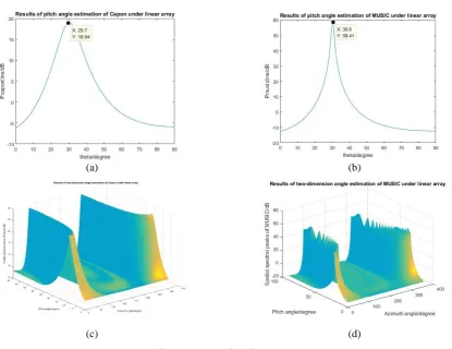
As shown in Fig. 1(a) and Fig. 1(b), when the one-dimensional elevation angle estimation is performed under ideal conditions, the estimated results of the Capon beamformer and the MSUIC algorithm are 29.7 ˚ and 30.6 ˚, respectively, and the errors are within 1˚. Comparing Fig. 1(a) and Fig. 1(b), it can be seen that the MUSIC algorithm has higher angular resolution than the Capon beamformer under the same array spacing and number of elements. However, when performing two-dimensional estimation of azimuth and elevation angles, the linear array will have a problem of fuzzy estimation of angles, as shown in Fig. 1(c) and Fig. 1(d).
(a) (b)
[image:4.595.98.514.401.721.2](c) (d)
Figure 1. Direction finding results of uniform linear antenna array.
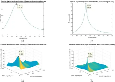
Simulation Results of Uniform Rectangular Antenna Array
estimation is performed, the pitch angle estimation results of the Capon beamformer and the MUSIC algorithm are 29.7 ˚ and 30.6 ˚, respectively, and the error are within 1˚. In the two-dimensional angle estimation, the estimated result of the Capon beamformer is (45 ˚, 30.6 ˚), the estimated result of the MUSIC algorithm is (45 ˚, 29.7 ˚), the azimuth angle estimation error is less than 1 ˚, and the pitch angle estimation angle error is less than 1 ˚. Whether it is a one-dimensional angle estimation or a two-dimensional angle estimation, the MUSIC algorithm has a higher angular resolution than the Capon beamformer, which shows that the peaks obtained by the search are sharper.
(a) (b)
[image:5.595.104.507.197.482.2](c) (d)
Figure 2. Direction finding results of uniform rectangular antenna array.
Conclusion
In this paper, the direction finding performance of the Capon beamformer and MUSIC algorithm for the single narrowband interference signal in the Beidou B3 band has been simulated. The simulation results show that the two algorithms can accurately estimate the pitch angle of the interference signal in both formations. When the algorithm is applied on the rectangular array, the azimuth of the interference direction can be estimated simultaneously.The mutual coupling between the array elements and the amplitude difference of the array elements will lead to the loss of the angular accuracy of the two algorithms. However, the mutual coupling of the array elements and the amplitude and phase difference matrix of the array elements can be obtained by using the active calibration method for the antenna elements. Error correction can be performed by using matrix inversion in the algorithm.
Acknowledgement
References
[1] Zhang W X, Xi-Cai S I, Jiang Y L. Research on phase error in the system of direction finding by phase interferometer, J. Systems Engineering & Electronics, 2006, 28(11):1631-1624.
[2] Fan G W, Bao-Guo Y U, Deng Z X, et al. Research on Adaptive Array Elements Calibration Algorithm in GNSS Interference Direction Detection, J. Computer Simulation, 2012.
[3] Gao X, Hong fei H U, De min F U. The effect of element mutual coupling on the performance of adaptive arrays, J. Journal of Xidian University, 2001.
[4] Hui Zhai, Xiaofei Zhang, Wang Zheng, DOA estimation of noncircular signals for coprime linear array via locally reduced-dimensional Capon, J. International Journal of Electronics.2018,105(5):709-724. DOI:10.1080/00207217.2017.1382011.
[5] Gou Xiaoming, Liu Zhiwen, Xu Yougen, et al, Biquaternion Capon beamformer using four-component vector-sensor arrays, J. International Journal of Sensor Networks. 2015, 19(3/4):171-180.
[6] Ribay, Guillemette, Chapuis, Bastien, Zabbal, Paul, et al, Multichannel Multiple Signal Classification for dispersion curves extraction of ultrasonic guided waves, J. The Journal of the Acoustical Society of America.2018, 143(2):EL87-EL92.
[7] Pan Hao, Zhang Fumin, Shi Chunzhao, et al, High-precision frequency estimation for frequency modulated continuous wave laser ranging using the multiple signal classification method, J. Applied optics.2017,56(24):6956-6961.