2018 3rd International Conference on Computational Modeling, Simulation and Applied Mathematics (CMSAM 2018) ISBN: 978-1-60595-035-8
Research on Application of Engine Assembly Process Design
Based on Assembly Simulation Technology
Chao LIU, Zhen-dong LIU, Hong-feng ZHAO and Qiao SUN
AECC Shenyang Engine Research Institute, Shenyang, China
Keywords: Assembly simulation technology, Engine assembly process design, Assembly simulation platform.
Abstract. This paper summarized the problems existing in the traditional assembly process design, and analyzed the advantages and applications of assembly simulation technology. In order to address the real issues of aero-engine production, a novel assembly process applied to assembly simulation platform was established by the combination of the professional knowledge of Aero-Engine Assembly and assembly simulation technology. The convenience for aero-engine assembly process design was brought by the key technologies in flow of three-dimensional process planning, interference checking, ergonomics simulation, working state analysis, simulation Video and interactive Graphical with examples of assembly simulation technology application introducing. The conclusion that the success rate of assembly process design will be greatly improved and the assembly operators can be provided efficient assembly guidance when the assembly simulation technology used to engine assembly process design in the simulation platform, was proved with examples of engine assembly engineering.
Introduction
Aero-Engine assembly process is the turnover flow program that parts, components, big components, unit bodies, and accessories form an engine, which includes the formulation of the
Process scheme, the planning of the process, etc.[1]. The traditional engine assembly process design
mainly depends on the process engineer's technical level, experience, and understanding of the engine's two-dimensional drawings and other data. The non-intuitionality of 2D engineering drawings has brought great difficulties to the design of engine assembly processes faced on complex structures. With the introduction of three-dimensional design software, the three-dimensional model of various types of engines and the assembly tooling models required for engines’ assembly have been basically complete. The time for the development of assembly simulation technology is ripe. And by assembly simulation technology, many problems in the
traditional engine assembly process design can be applied to solve.[2].
Problems in Traditional Engine Assembly Process Design
The traditional assembly process design refers to the engine assembly process design method based on two-dimensional drawings. Its characteristic lies in transmitting engine structure and assembly relationship information by 2D drawings. The complex assembly process relies entirely on the experience and conjecture of the process engineer when the process is planned, but also the physical assembly inspection is the only assembly inspection method. The process design results are only expressed to workers by 2D drawings. It lacks consideration of the entire assembly process for this process design method. And it is difficult to find and analyze the human factors in the assembly
process[3], as well as the impact on the actual factors such as gravity. The main problems in
traditional assembly process design are summarized as follows 6 points:
1) The process planning cycle is long and the level of optimization is low. The traditional
process planning is two-dimensional planning, and the process engineer needs to consult a
large number of drawings and documents to digest and absorb[4]. This requires a long-term
compare and optimize multiple sets of process plans to form the final plan during the process planning stage.
2) One-time success rate for assembly tooling design is low. The environment in
two-dimensional design does not have three-dimensional detection capability. There are few effective testing methods for some interference or unreasonable parts in tooling design, which is the root cause of the one-time success rate.
3) During the process design, the coordination among humans, machines, and the
environment in different operations cannot be analyzed. The conflict in human strength and movement and the use of tool space requirements leads to the difficulty of achieving the process plan due to the worker's operational factors or the use of tools. .
4) The process design is carried out in the mind of the process engineer, and the actual
assembly process will have a variety of different factors, such as gravity, centrifugal force in the assembly process, etc. These factors are difficult to completely took into account in the imagination so they are always ignored. It will lead to mistakes in the process plan and deviations in the implementation process.
5) Works lack effective training materials. At present, the process engineer mainly explains
the implementation process and train workers based on two-dimensional drawings and assembly procedures. The structure of the engine is complex, but this teaching material lacks vivid, intuitive and dynamic teaching methods as a demonstration, resulting in a long training cycle, low efficiency, and rising labor costs.
6) Processing procedure which uses two-dimensional drawings and explanatory documents as
the main content, expresses the assembly process information by two-dimensional engineering drawings, is poor of visual and interactive nature.It is necessary to express assembly information with a large number of words, which leads to poor comprehensibility and ambiguity.
Assembly Process Design Based on Assembly Simulation Technology
Assembly simulation is a technology based on the three-dimensional solid model of the product, using computer technology, information technology and artificial intelligence technology to plan
assembly process and simulate the actual assembly process[5]. Assembly process design based on
assembly simulation is one of the key technologies for digital design and manufacturing. It is mainly based on the three-dimensional model of the product to conduct a comprehensive modeling and simulation of the engine assembly process, including assembly path planning, human-machine coordination operation simulation, Tolerance analysis, ergonomics simulation, etc. It provides complete solutions with product assembly verification, assembly process planning and analysis, assembly operation training and guidance, and assembly process demonstration for the design and
manufacture of various complex products[6].
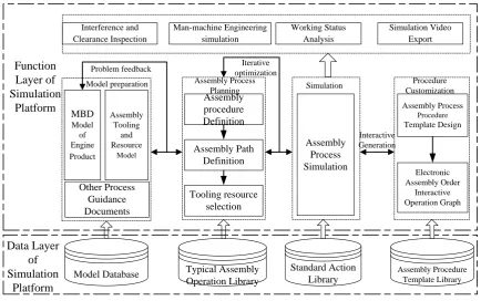
Other Process Guidance Documents Assembly Tooling and Resource Model MBD Model of Engine Product Assembly procedure Definition Assembly Path Definition Tooling resource selection Typical Assembly Operation Library Assembly Process Planning Assembly Process Simulation Simulation Assembly Process Procedure Template Design Electronic Assembly Order Interactive Operation Graph Assembly Procedure Template Library Procedure Customization Man-machine Engineering simulation Standard Action Library Model preparation Model Database Iterative optimization Interactive Generation Problem feedback Working Status Analysis Simulation Video Export Interference and Clearance Inspection Function Layer of Simulation Platform Data Layer of Simulation Platform
Figure 1. Assembly process design flow in simulation platform.
The assembly process design based on assembly simulation technology takes the 3D model as the sole headstream of data. A virtual assembly environment is established on the simulation platform. With assembly simulation as the core technical process, it solves the problems that the traditional engine assembly process design mainly relies on the assembly experience and knowledge of some process engineers, as well as the difficulty of design, low efficiency, and low optimization level. The three-dimensional process planning technology, interferometric gap inspection technology, human-machine simulation technology, working status analysis technology, simulation video output technology, interactive graphic preparation technology and other assembly simulation key technologies of assembly simulation can effectively complete the BOM reconstruction, and introduce practical factors and Human-machine influence, simulation inspection of process planning results, and production of concise and easy-to-understand process diagrams and assembly guidance videos, which can solve the above-mentioned problems in traditional assembly to a large extent.
Application of Key Technologies in Assembly Simulation
Three-dimensional Process Planning Technology
The 3D process planning technology uses engine 3D numerical simulation and design BOM to directly perform engine assembly process planning within the simulation platform, formulate component model assembly sequence and assembly path, and validates the feasibility and rationality of assembly sequence and assembly path planning through simulation. . It is very convenient to deal with the model in the three-dimensional environment. The process engineer can design multiple sets of solutions and verify its rationality.
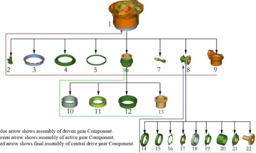
At present, the Three-dimensional process planning method is mainly adopted “The product can be assembled which can be installed”. The disassembly sequence of the product is determined by disassembling the assembly model, and the order of disassembly sequence is the assembly inverted sequence of the product.
sequence of each component is obtained in reverse order. According to the dismantling result, the entire assembly is divided into driven gear component assembling (assembly sequence such as blue line display), drive gear component assembling (assembly sequence as green line display), central drive gear component final assembling (assembly sequence as red line display), as three big processes, twenty-one steps.
Figure 2. Three-dimensional planning for assembly sequence.
Through the three-dimensional process planning technology, the efficiency of assembly planning is greatly improved, and the conversion of the product from the design BOM to the process BOM is completed quickly. Its intuitive expression, clear separation plane, can be convenience for the process engineer to plan and verify a variety of programs. Assembly planning through 3D models reduces the time required for consulting a large number of drawings. The planning results can be visually verified through the model, greatly improving the efficiency and quality of assembly process design.
Interference and Space Clearance Inspection Technology
The function of interference and space clearance inspection is used to perform collision analysis, contact analysis and clearance analysis on the assembly model, and determine the degree of interference between the components. Interference can be divided into static interference and dynamic interference. Static interference mainly due to design errors, there are defects in the geometry and size of parts, resulting in interference between the internal parts of the assembly and parts. Dynamic interference refers to the collision between the movement of the parts and the rest of the assembly.
Interference and space clearance inspection is an important method to determine whether the assembly tooling design is reasonable. The reality shows that the assembly tooling design fails, mostly because of interference, and the interference directly affects the rationality of the tooling design. Before the tooling design is finalized, it must be eliminated.
After the assembly tooling model is assembled with the engine model, it is possible to visually inspect whether there is static interference between the tooling and the engine model through the static interference. With the dynamic simulation of the tooling function, interactive interference inspection can be used to visually detect whether there is dynamic interference in the tooling model during it using with the engine.
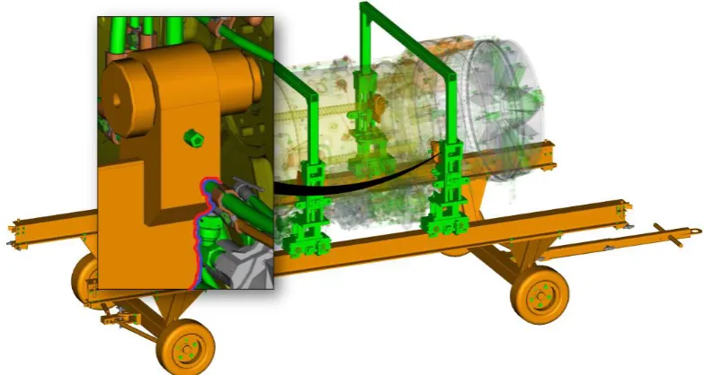
unreasonable design of the bracket and the interference between the bracket and the engine pipeline, it is necessary to extend the support shaft and adjust the bracket outwards.
Figure 3. Result of intervention analysis.
The interference and space clearance inspection can help process engineer to discover the defects or errors in the assembly tooling design during the design phase. This has great significance for improving the quality of the tooling design, saves the tooling design cost and ensures the model assembly cycle. With interference and space clearance analysis, structural interference that is difficult to find in a two-dimensional design environment can be visually displayed in the three-dimensional model, improving the one-time success rate of tooling design.
Ergonomics Simulation Technology
The ergonomics simulation technology ensures the feasibility and comfort of workers when
performing process operations and ensures the high quality of assembly work.[7] According to the
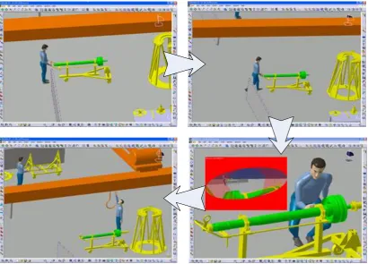
process planning, a assembly tool instance is selected from the tool library for simulation, and the corresponding posture of the human body is matched from the human posture database to realize the motion association between the tool and the human posture. Analyze the point of view of the assembly operator, verify and analyze the accessibility of the tool in combination with the visual range, simulate the human work and perform comfort analysis, and determine the excellent accessibility of the tool according to the visual range of the viewpoint and the requirements of the operation. For the unreachable situation, modify the assembly tool to modify and improve the process, such as tool transformation, human posture transformation, viewpoint conversion.
Figure 4. Man-machine engineering simulation.
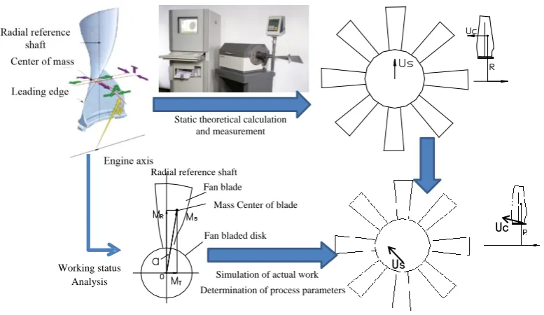
Working Status Analysis Technology
During the actual assembly process of the engine, due to the effects of temperature, rotation speed, etc., the assembly parameters of the working state and the theoretical state of the machine parts will
change, thereby affecting the engine assembly results[8]. By simulating the working state of the
engine, applying the corresponding simulation algorithm, introducing the actual force of the product and the assembly force generated by the assembly process, analyzing the changes of the parameters under the working state of the product, and predicting the actual assembly process under the state of the theoretical model. Simulate the actual state of various parameters, thereby iterating on the process, improves assembly quality.
Us
Uc
Simulation of actual work Determination of process parameters
Working status Analysis
Radial reference shaft Fan blade
Mass Center of blade
Fan bladed disk Static theoretical calculation
[image:7.595.103.492.71.296.2]and measurement
Figure 5. Working status analysis.
Simulation Video Export Technology
The number of engine parts is numerous, and the assembly movements are basically three kinds of movements, translations, rotations, deformations and their combinations. On the time series, the assembly sequence and assembly movements are coordinated with the adjustment of visual angle (convenient observation), with necessary rendering and assembly highlights, which form corresponding assembly animation to demonstrate assembly process of engine parts. And it can be used to guide field assembly.
The assembly process simulation is an iterative optimization process for the assembly process design. The simulation animation and video generated by it can effectively guide the field assembly. It is the best training material. It intuitively and vividly demonstrates the real process of the engine parts assembly. The assembly operator can clearly understand the assembly operation steps, deepen their understanding of the entire operation process, and play an exemplary role, thereby improving work efficiency and assembly quality, and reducing mis-operation. The use of three-dimensional animation training for assembly operators, intuitive, visual and efficient, saves a lot of training costs.
Figure. 6 is a simulation video of the assembly of the high-pressure turbine rotor. The mode of video is a vector. It can be flipped and free-scalable, making it easy for the assembly operator to observe in all directions. The main window demonstrates the assembly process of the vortex rotor. The film below is an index of the video. Click on this to immediately demonstrate the assembly of the step.
[image:7.595.143.453.604.780.2]Interactive Graphical Technology
The three-dimensional illustration is a high-definition picture with a three-dimensional effect that is output using the assembly simulation software. With the simulation software, the three-dimensional illustration of the simulation output can be provided with the interactive function to the users. At the same time the engine structural information and the operation guide of assembly tooling method can be expressed visually.
In the three-dimensional illustration, the axial explosion map can roughly illustrate the assembly sequence of the parts of the product. The Section Cuts of three-dimensional is used to express the internal structure of the assembly body and the relative position relationship of parts. The three-dimensional annotation can accurately represent the mutual installation positions of the parts. Using of partial enlarged drawing can express the details of the assembly, and perspective or transparent for assembly body can be enable to see the internal structure of the assembly. Users can quickly locate and browse all structure of engine and assembly tooling by clicking, selecting and other operations. The comprehensive application of these methods can intuitively describe the engine assembly information.
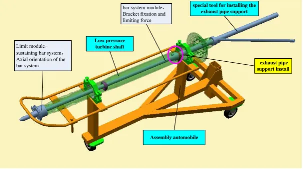
The complex assembly information of the engine can be intuitively transmitted by the three-dimensional illustration to form an effective interaction mode, which will greatly improve the understandability of the processing procedure. The three-dimensional illustration is used in the assembly process procedure, as shown in Figure 7, which replaces the original two-dimensional diagram will greatly increase the comprehensibility of the process specification, and avoid the occurrence of mis-assembly and missing- assembly due to misunderstandings.
bar system module,
Bracket fixation and limiting force
Limit module,
sustaining bar system,
Axial orientation of the bar system
Low pressure turbine shaft
Assembly automobile
special tool for installing the exhaust pipe support
[image:8.595.148.451.374.543.2]exhaust pipe support install
Figure 7. Three-Dimension Graphics.
Conclusion
This article describes the procedure of engine assembly process design in the assembly simulation platform, as well as the application research and specific practice of its six key technologies in the engine assembly process design. By the research work of this dissertation, it is verified that assembly process design based on assembly simulation technology is an effective method for planning, testing engine assembly process and exploring optimization schemes, and can solve many problems in the procedure of engine traditional assembly process design.
References
[1] C. Wang , H. Yu, W. Zhang, et al. Object-oriented Aero-engine Assembly Models, J. Computer
Integrated Manufacturing Systems Cims, 16(2010) 942-948.
[2] C. Marriott, J. Chebib. Emergence-focused designing complex system simulation, European
[3] K. Xu, R. Qu, J. Wang. Aircraft assembly system model based on MIMPN, J. Computer Integrated Manufacturing Systems Cims, 21(2015) 2022-2032.
[4] E. Varga, A. Piros, B. Vidovics. Simulation Challenges In The Development Process Of A
Complex Product: Design Of Virtual Electric Sports Car, Conference on Modeling and Simulation. 2014, pp. 122-128.
[5] W.J. Tolone, E.W. Johnson, K.J. Thieman, et al. Multi-infrastructure modeling and simulation
system, US 8,473,263 (2013).
[6] M. Alemanni, F. Destefanis, E. Vezzetti. Model-based definition design in the product lifecycle
management scenario, J. International Journal of Advanced Manufacturing Technology, 1-4(2011), 1-14.
[7] N.I. Badler, W.M. Becket. B.L. Webber. Simulation and analysis of complex human tasks for
manufacturing. Information on http://mirror.im pa.br/sibgrapi96/trabs/pdf/p01.pdf, 2003.
[8] F.Y. Liu. An Optimal Design Method for Simulation Verification, Validation and Accreditation