http://dx.doi.org/10.4236/cs.2016.76064
How to cite this paper: Gopalakrishnan, S. and Kumar, P.M. (2016) Performance Analysis of Malicious Node Detection and Elimination Using Clustering Approach on MANET. Circuits and Systems, 7, 748-758.
http://dx.doi.org/10.4236/cs.2016.76064
Performance Analysis of Malicious Node
Detection and Elimination Using Clustering
Approach on MANET
S. Gopalakrishnan
1*, P. Mohan Kumar
21Department of Electronics & Communication Engineering, PSNA College of Engineering and Technology, Dindigul, India
2Department of Computer Science and Engineering, Jeppiaar Engineering College, Chennai, India
Received 7 March 2016; accepted 9 May 2016; published 12 May 2016
Copyright © 2016 by authors and Scientific Research Publishing Inc.
This work is licensed under the Creative Commons Attribution International License (CC BY).
http://creativecommons.org/licenses/by/4.0/
Abstract
Mobile Ad hoc Network (MANET) is a significant concept of wireless networks which comprises of thousands of nodes that are mobile as well as autonomous and they do not requires any existing network infrastructure. The autonomous nodes can freely and randomly move within the network which can create temporary dynamic network and these networks can change their topology fre-quently. The security is the primary issue in MANET which degrades the network performance significantly. In this paper, cluster based malicious node detection methodology is proposed to detect and remove the malicious nodes. Each node within the cluster gets the cluster key from the cluster head and this key is used for the data transaction between cluster head and node. The cluster head checks this key for every data transaction from node and match with their cluster ta-ble. If match is valid, and then only it will recognize that this node is belongs to this cluster, other-wise it is decided as malicious node. This paper also discusses the detection of link failure due to the presence of malicious node by determining the gain of each link in the network. The perfor-mance of the proposed method is analyzed using packet delivery ratio, network life time, and throughput and energy consumption. The proposed malicious node detection system is compared with the conventional techniques as OEERP (Optimized energy efficient routing protocol), LEACH (Low energy adaptive clustering hierarchy), DRINA (Data routing for In-network aggregation) and BCDCP (Base station controlled dynamic clustering protocol).
Keywords
Malicious Node, Cluster Formation, MANET, Cluster Head
1. Introduction
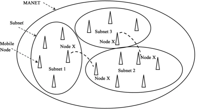
Mobile Ad hoc networks (MANETs) are the currently emerging communication infrastructure which finds its application in several significant fields such as mobile devices and military applications in case of disaster and other crisis operations. MANETs are defined as the category of wireless networks that utilize multi-hop radio relaying and are capable of operating without the support of any fixed infrastructure (i.e. infrastructure less). The absence of any central coordinator or base station makes the routing a complex one compared to cellular net-works. Ad hoc wireless network topology for the mobile network is shown inFigure 1. The communication between two nodes far apart takes place through an intermediate node. In a MANET, the routing and resource management are done in a distributed manner in which all nodes coordinate to enable communication among them. This requires each node to be more intelligent so that it can function both as a network host for transmit-ting and receiving data and as a network router for routransmit-ting packets from other nodes.
MANETs are susceptible to extensive ranges of security attack which is mostly caused due to its rapid real time exploitation, infrastructure-less wireless communication channels, and the hostile environments in which they may be deployed, making them susceptible to a wide range of security attacks described in [1]-[3]. Due to the quick and economically less demanding deployment of MANETs, they are used in military applications, collaborative and distributed computing emergency operations, etc. The security of communication in MANET is very important, especially in military applications. The lack of any central coordination and shared wireless medium makes them more vulnerable to attacks than wired networks.
Many research works have focused on the security of MANETs. Most of them deal with prevention and de-tection approaches to combat individual misbehaving nodes. Generally, the attacks against MANETs can be classified into two types: passive and active attacks. Passive attacks refer to the attempts made by malicious nodes to perceive the activities, whereas the active attacks are attacks performed by the malicious nodes that bear some energy cost to perform the attack. When more malicious nodes join together, then they perform a col-laborative attack, causing more destructive damages to the network. In such a situation, a malicious node (black hole node) attracts all the packets using forged Route Reply (RREP) packet to wrongly choose the “fake” short-est route towards the dshort-estination and then discard these packets without forwarding them to the dshort-estination. In the case of gray-hole attacks, a node is not initially recognized as malicious since it turns malicious only at a lat-er stage, thus a secure communication cannot be plat-erformed since its existence within the network cannot be identified. The malicious node then selectively forwards or discards the data packets as the packets go through it.
[image:2.595.145.486.513.704.2]The various categories of attacks produced by the malicious nodes include Rushing attack, Black hole attack, Neighbor attack, Jellyfish attack and Denial of Service (DoS) attack. In Black hole attacks, all data packets are received on other paths instead of the actual routing path. In Rushing attack, as the source nodes flood the net-work with route discovery packets to locate routes to the destinations, each intermediate node processes only the
first original packets and the duplicate packets are discarded which arrives later on. A rushing attacker makes use of this duplicate suppression mechanism by quickly forwarding route discovery packets to access the for-warding group. In Jellyfish attack, the forfor-warding group is first intruded and then the data packets are delayed unnecessarily for a certain time before forwarding. These results in significantly high end-to-end delay and thus the performance of real-time applications get degraded. Neighbor attack is that, upon receiving a packet, an in-termediate node records its ID in the packet before forwarding the packet to the next node. An attacker simply forwards the packet without recording its ID in the packet making two nodes that are not within the communica-tion range of each other to believe that they are neighbors. Denial-of-Service attack is an attack, in which the nodes are prohibited to send and receive data packets to its destinations.
In this paper we have taken insight of intrusion detection systems and different attacks on MANET security. Then we propose a technique in cluster based intrusion detection system which eliminates the malicious nodes.
2. Literature Survey
Chand et al. [4] proposed a cluster-based routing protocol “Optimized Energy Efficient Routing Protocol” (OEERP) using the principle of uniform battery drain of nodes. The election of Cluster Head (CH) occurs ran-domly and once the cluster head is selected, the CH broadcasts an advertisement message to all the nodes. A few nodes that are left out during cluster formation may become a member of any other cluster or may become a cluster head of any other cluster. Singh et al. [5] presented LEACH (Low Energy Adaptive Clustering Hierarchy) protocol to form a cluster of self-organizing nodes. The cluster heads were selected in a random manner based on the highest energy and accessibility. The selected cluster head performed data fusion for data compression and helped in increasing the network lifetime and throughput. The entire knowledge of the network was not ne-cessary to cluster the nodes in the wireless environment, in this protocol.
Abidoye et al.[6] have made use of Data Routing for In-Network Aggregation (DRINA) protocol which per-forms Routing Tree construction to find the shortest path linking all the nodes within the network. The base sta-tion after receiving the node’s informasta-tion, it starts the formasta-tion of clusters using these nodes. The intermediate nodes between the cluster head and the destination node are called Relay nodes and forward the sensed data. Chatterjee et al.[7] proposed the Base-station Controlled Dynamic Clustering Protocol (BCDCP) for the routing of a centralized network. The base station after receiving the energy level of all the sensor nodes, cluster forma-tion is performed and the cluster head is selected. This method splits the whole network into two sub-clusters, and then further into many small clusters up to the required level. The Cluster Heads are placed far apart within the network to provide uniform coverage all over the network. The BCDCP method implemented CH to CH multi-hop routing scheme using the minimum spanning tree, to identify the lowest energy path for routing and to forward the messages like Cluster formation and CH information in this route.
Rejina Parvin and Vasanthanayaki [8] have used Particle Swarm Optimization (PSO) based clustering algo-rithm for the detection of residual nodes in wireless sensor networks. The implementation of PSO avoids indi-vidual node formation since clustering is performed until every node becomes a member of any other cluster, thus improving the network lifetime. Using this method, the term force between the CHs is considered during route construction phase to determine the next best hop. Chang et al.[9] implemented Cooperative Bait Detec-tion Approach for the detecDetec-tion of malicious nodes in MANETs. Their method attempted to detect the malicious nodes by designing a dynamic source routing (DSR)-based routing mechanism, which is referred to as the coop-erative bait detection scheme (CBDS), which is a combination of both proactive and reactive defense schemes.
Proactive detection schemes [10]-[14] are schemes that constantly detect or monitor the nearby nodes. In these schemes, despite the existence of malicious nodes, the overhead of detection is constantly created. Liu et al. [12] proposed a 2ACK Proactive detection scheme to detect the routing misbehaviors in MANET. In their method, after the data packets are successfully received, the two-hop acknowledgement packets are sent in the opposite direction to signify the successful reception of packet. Deng et al.[13] designed Mobility Based Clus-tering (MBC) protocol, in which all the sensor nodes possess an opportunity in electing the cluster head based on the threshold value. MBC protocol performed better than LEACH, HEED and other protocols on mobili-ty-based environment, but failed to address the critical node occurrence problem which causes packet dropping, link breakage and reduces the network utilization.
de-livery ratio and delay) to be chosen by the destination node. The source node selects a different route under the situation that the path deviates from a predefined behavior set for determining “good” routes. The main demerit of BFTR is that malicious nodes may still exist in the new chosen route, and this scheme is subjected to repeated route discovery processes.
The conventional methods were based on clustering and no security issues were considered. The link failure due to malicious nodes was considered in the conventional protocol. This paper proposes a malicious node de-tection technique using clustering based approach and provides solution for link loss due to malicious nodes. It will increase the performance of the MANET system.
3. Proposed Method
3.1. Cluster Based Malicious Node Detection
[image:4.595.137.537.398.718.2]MANET consists of number of nodes spreading over a certain area. The nodes are grouped into smaller regions, which are called as cluster. Each cluster has cluster head (CH) and it is responsible for controlling all the nodes within their limit. MANET consists of number of CHs and all CHs are linked with the sink. One CH can directly transmit the packet to the sink or through other CHs. Each CH maintains a cluster table and each node maintains a neighbor table. The cluster table consists of the details of all nodes, the distance from cluster head to each node within the cluster and cluster key.
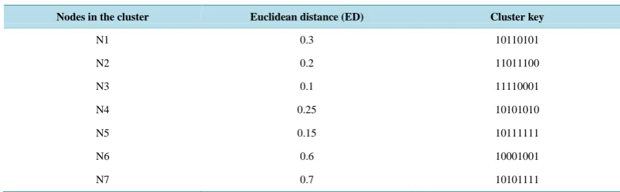
Figure 2shows the cluster formation in MANET environment. It consists of clusters named as Cluster 1 and Cluster 2. Cluster 1 contains the nodes N1 to N7 and it maintains a cluster table. The format for cluster table of each cluster is given as described in Table 1.
Each node within the cluster gets the cluster key from the cluster head and this key is used for the data trans-action between cluster head and node. The cluster head checks this key for every data transtrans-action from node and match with their cluster table. If match is valid, and then only it will recognize that this node is belongs to this cluster.
[image:4.595.85.537.579.719.2]Figure 2. Cluster based malicious node detection.
Table 1. Cluster table for the nodes in a cluster.
Nodes in the cluster Euclidean distance (ED) Cluster key
N1 0.3 10110101
N2 0.2 11011100
N3 0.1 11110001
N4 0.25 10101010
N5 0.15 10111111
N6 0.6 10001001
3.2. Determination of Euclidean Distance (ED)
The Euclidean distance (ED) between each node within a cluster and cluster head is determined using the fol-lowing expression,
(
) (
2)
22 1 2 1
ED= x −x − y −y (1)
where, (x1, x2) represents the coordinates of the cluster head location and (y1, y2) represents the coordinates of the node within the cluster. The Euclidean distances are variable due to the mobility of the nodes in and out from the cluster. The mobility of the node can be determined as,
(
)
(
)
1 1– 1 1
node t t t t t
V =W V∗ − + P− P− +W∗ P− ∗P (2)
where, W denotes the weight of the node, Vt-1 is the previous velocity of the node, Pt-1 is previous location of the node and Pt is the current location of the node. The weight of each node can be computed as,
1 1 2 2 3 3
W =a ∗x +a ∗x +a ∗x (3) where, “a1” and “a2” represents constant value and it follows {a1, a2} ε {0 to 1}; and a3 = − −1 a1 a2
(
)
1 ch– i n
x =
∑
d d c (4)where,
(
dch –di)
denotes the distance from cluster head to the neighbouring nodes around the cluster head andcn denotes number of cluster heads.
2 n n
x =E c (5)
3 1 n
x = c (6)
3.3. Determination of Number of Clusters
Number of clusters in a mobile ad-hoc network can be found by the Equation (7),
clusters M N N X Y ∗ =
∗ (7) where, M and N represent the width and height of the network area, respectively. X and Y represent the width and height of each cluster area, respectively. Let us assume the width and height of each cluster is equal and it is assumed as X = =Y t. Then Equation (7) can be re-written as,
2 clusters M N N t ∗
= (8)
The radius “r” of each cluster is related with t and it is given as, 2
t= ∗r (9) Then, Equation (9) can be written as,
2 2 clusters M N N r ∗ =
∗ (10)
3.4. Determination of Cluster Key
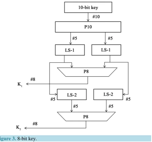
Cluster head in a cluster delivers 8-bit key to each node available within the cluster. The 8-bit key is individually allotted to each node and the flow of generating the node key is illustrated in Figure 3.
Figure 3. 8-bit key.
The permutation the 10-bit key can be obtained as
Let the 10-bit key be designated as (k1, k2, k3, k4, k5, k6, k7, k8, k9, k10). Then the permutation P10 is de-fined as:
(
) (
)
P10 k1, k2, k3, k4, k5, k6, k7, k8, k9, k10 = k3, k5, k2, k7, k4, k10, k1, k9, k8, k6 .
The following procedure is adopted for generating first 8-bit key as,
Step 1: For example, the key (1010000010) is permuted to (1000001100).
Step 2: Divide (1000001100) into a left part 5-bit value (10000) and a right part 5-bit value (01100).
Step 3: Perform a circular left shift (LS-1), or rotation, separately. The left value (10000) becomes (00001). The right value (01100) becomes (11000). Concatenate the left part (00001) and the right part (11000) into a 10-bit value (0000111000).
Step 4: Pick out and permute 8, (don’t use 1 and 2) which will generate first 8-bit key (K1), of the 10 bits ac-cording to the following rules:
Step 5: Follow the same procedure for LS-2 to generate next 8-bit key “K2”
Step 6: XOR the two 8-bits K1 and K2 and resultant 8-bit key is assigned as node key for the first node within the cluster.
Step 7: Initial 10-bit key is changed randomly and apply the steps 1 to 6 inorder to generate the next 8-bit key for the next node within the cluster.
3.5. Algorithm to Remove the Malicious Node
[image:6.595.183.450.83.332.2]Step 1: The cluster head finds the malicious node and add this node to malicious node list available in cluster table.
Step 2: Send this malicious node list to all the cluster heads in the MANET.
Step 3: All cluster heads broadcast this information to their corresponding nodes within their cluster limit.
3.6. Detection of Link Faults
The link faults in the mobile adhoc networks will affect the performance of the routing. The faults in the net-work occur due to the link failure between nodes in the netnet-work. The faults are categorized into persistent faults and transient faults. The faults in the network can be occurred due to the following reasons:
Low battery in nodes in the network. Physical/Hardware problem. Obstacles in the nodes.
The faults in the node due to the above reasons are called as persistent faults. Transient noises are occurred due to background noises. In this paper, the persistent faults are detected and alternate routing is selected. The lossy of the link in the node is determined by estimating average loss rate in the node.
Figure 4 shows the detection of link failure based on link cost algorithm. There are three primary source nodes s1, s2 and s3. All these three source nodes send the data to the sink. Node s1 use the links l2 and l1 to reach the sink. Node s2 use the links l3 and l1 to reach the sink. Node s3 use the links l4 and l1 to reach the sink. The node s3 also may send the data to the sink through link l5. Each link in the network has 1 unit link cost. Assume link l1 and l5 are lossy links. These lossy links can be determined using link cost algorithm as described in the following:
Step 1: Determine the probability of the link to be lossy. In Figure 4, there are five links and each link has 0.2 probabilities for a link to be lossy.
Step 2: Determine the number of possible fault path from source node to sink. Here, we have four number of fault path as fp1 = {l2, l1}, fp2 = {l3, l1}, fp3 = {l4, l1} and fp4 = {l5}.
Step 3: Find the gain of each link in the network as described in Equation (11).
(
1)
k pk kb pk kg Ck
Φ = ⋅Φ + − ⋅Φ − (11)
where, pk is the probability of a link to be fault.
kb
Φ is the cost of the link when the particular link is fault.
kg
Φ is the cost of the link when the particular link is not-fault and Ckis the cost of the link to be tested.
Step 4: Find the lowest gain of the link and this link is concluded as a faulty link.
The following parameters are used to determine the performance of the proposed method. Packet delivery ratio (PDR):
It is defined as the ratio of the number of packets correctly received at the destination node to the total number of packets sent by the source node. The average packet delivery ratio is given by the expression as:
Packets d Packets s
N PDR
N =
∑
∑
(12)where, NPackets d is the number of packets received at the destination node and NPackets s is the number of pack-ets sent from the source node.
Network life time:
It is defined as the total time taken for the packet to reach the destination from source node. The network life time will be high when there are large numbers of nodes between source and destination node.
Throughput:
The rate at which the total amount of packets transmitted from source to destination node over a time period “t” is called as throughput. It is simply defined as the number of bits transmitted per second. It is expressed as,
Throughput=
∑
Total number of bits time ‘’t (13)Throughput is defined as the number of bits successfully transmitted to the destination over a time period.
4. Results and Discussion
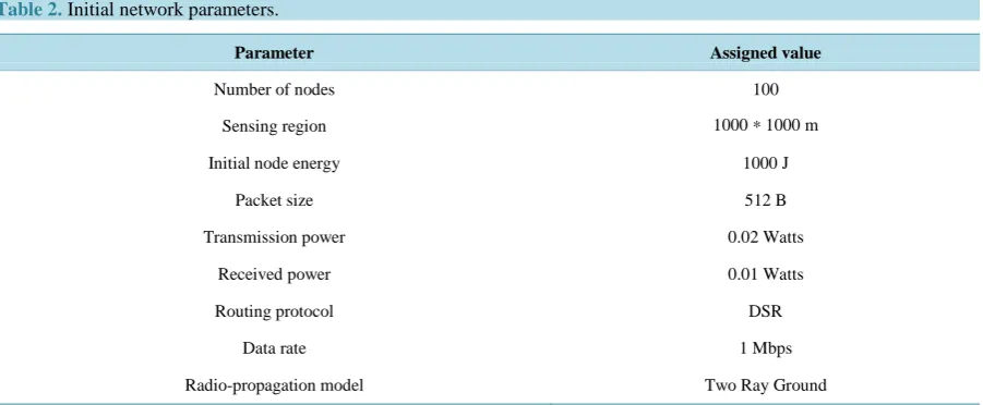
The proposed clustering technique is implemented using Network Simulator 2.0. For measuring performance analysis purpose, we have carried out a thorough experimental analysis to understand the impact of the proposed clustering mechanism on MANET. Table 2 shows the initial network parameters for performance evaluation. Total number of nodes used in this paper is 100 and these nodes are spread over 1000 × 1000 m. Each node has 1000 J of initial energy and packet size of 512 bytes.
The proposed malicious node detection system is compared with the conventional techniques as OEERP (Op-timized energy efficient routing protocol) [3], LEACH (Low energy adaptive clustering hierarchy) [4], DRINA (Data routing for In-network aggregation) [5] and BCDCP (Base station controlled dynamic clustering protocol) [6] using the following performance evaluation parameters.
Packet delivery ratio (PDR):
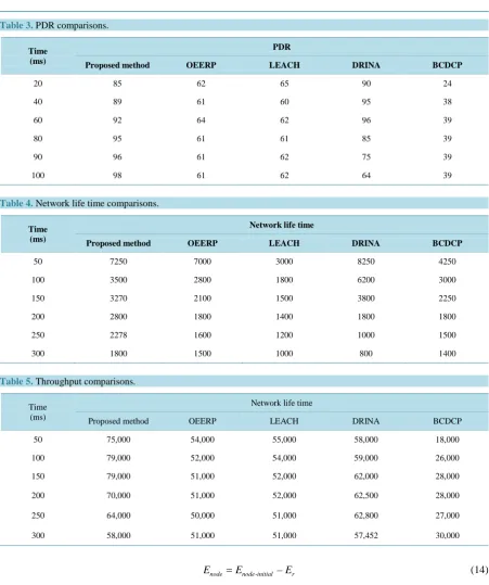
PDR defines the percentage of number of packets correctly received at the receiver side. For better perfor-mance of the system, PDR should be high. The PDR is high when there is a high number of nodes between source and destination and it will reduces the packet losses. Table 3 shows the PDR of the proposed system with conventional system. The PDR gradually increases over linear increment of number of nodes in the proposed system. The maximum PDR achieved in proposed system is 98% at 300 ms time duration.
Network life time:
The network life time will be high when there are large numbers of nodes between source and destination node. Table 4shows the network life time over different time period of the proposed method with conventional methods.
Throughput:
Throughput is defined as the number of bits successfully transmitted to the destination over a time period. The performance of the system is improved if the throughput is high.Table 5 shows the performance comparisons of proposed method with different conventional protocols. From Table 5, the throughput of the proposed system is proved to be better than the conventional systems.
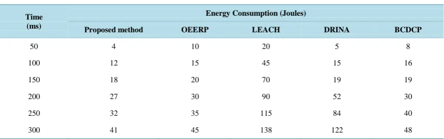
Energy consumption
[image:8.595.89.540.536.722.2]The network life time can be improved by reducing total energy consumption. The energy consumption of the node is based on sensing the data, conversion from one format to another format and transmission. The energy consumption of the individual node in MANET is computed as,
Table 2. Initial network parameters.
Parameter Assigned value
Number of nodes 100
Sensing region 1000 * 1000 m
Initial node energy 1000 J
Packet size 512 B
Transmission power 0.02 Watts
Received power 0.01 Watts
Routing protocol DSR
Data rate 1 Mbps
Table 3. PDR comparisons.
Time (ms)
PDR
Proposed method OEERP LEACH DRINA BCDCP
20 85 62 65 90 24
40 89 61 60 95 38
60 92 64 62 96 39
80 95 61 61 85 39
90 96 61 62 75 39
100 98 61 62 64 39
Table 4. Network life time comparisons.
Time (ms)
Network life time
Proposed method OEERP LEACH DRINA BCDCP
50 7250 7000 3000 8250 4250
100 3500 2800 1800 6200 3000
150 3270 2100 1500 3800 2250
200 2800 1800 1400 1800 1800
250 2278 1600 1200 1000 1500
[image:9.595.87.539.67.607.2]300 1800 1500 1000 800 1400
Table 5. Throughput comparisons.
Time (ms)
Network life time
Proposed method OEERP LEACH DRINA BCDCP
50 75,000 54,000 55,000 58,000 18,000
100 79,000 52,000 54,000 59,000 26,000
150 79,000 51,000 52,000 62,000 28,000
200 70,000 51,000 52,000 62,500 28,000
250 64,000 50,000 51,000 62,800 27,000
300 58,000 51,000 51,000 57,452 30,000
- –
node node initial r
E =E E (14)
where, the initial energy of the node is denoted as Enode initial- and the energy after processing the data is denoted as Er
The total energy consumption of the network is computed as,
_ 1
n
network i node i
E =
∑
=E (15)where, “n” represent number of nodes in the network.
Table 6. Energy consumption comparisons.
Time (ms)
Energy Consumption (Joules)
Proposed method OEERP LEACH DRINA BCDCP
50 4 10 20 5 8
100 12 15 45 15 16
150 18 20 70 19 19
200 27 30 90 52 30
250 32 35 115 84 40
300 41 45 138 122 48
The energy consumption of the proposed method is compared with other protocols OEERP, LEACH, DRINA and BCDCP. From Table 6, there is a linear increment of energy consumption over different time slots. The proposed method consumes low energy consumption when compared with other conventional protocols. The network life time will be improved by consuming less energy.
5. Conclusion
The malicious nodes in the MANET are detected and removed using clustering approach. Each node within the cluster gets the cluster key from the cluster head and this key is used for the data transaction between cluster head and node. The cluster head checks this key for every data transaction from node and matches with their cluster table. If the match is valid, then only it will recognize that this node is belongs to this cluster, otherwise it is decided as malicious node. This paper also discusses the detection of link failure due to the presence of mali-cious nodes by determining the gain of each link in the network.
References
[1] Nguyen, H.L. and Nguyen, U.T. (2008) A Study of Different Types of Attacks on Multicast in Mobile Ad Hoc Net-works. Ad Hoc Networks, 6, 32-46. http://dx.doi.org/10.1016/j.adhoc.2006.07.005
[2] Karmore, P. and Bodkhe, S. (2011) A Survey on Intrusion in Ad Hoc Networks and its Detection Measures. Interna-tional Journal on Computer Science and Engineering, Chennai.
[3] Rai, A.K., Tewari, R.R. and Upadhyay, S.K. (2010) Different Types of Attacks on Integrated MANET. Internet Com-munication. International Journal of Computer Science and Security, 4.
[4] Chand, K.K., Bharati, P.V. and Ramanjaneyulu, B.S. (2012) Optimized Energy Efficient Routing Protocol for Life- Time Improvement in Wireless Sensor Networks. Proc. Int. Conf. Adv. Eng., Sci. Manage. (ICAESM), 345-349.
[5] Singh, S.K., Singh, M.P. and Singh, D.K. (2010) Routing Protocols in Wireless Sensor Networks—A Survey. Interna-tional Journal of Computer Science and Engineering Survey, 1, 63-83. http://dx.doi.org/10.5121/ijcses.2010.1206
[6] Abidoye, A.P., Azeez, N.A., Adesina, A.O. and Agbele, K.K. (2011) ANCAEE: A Novel Clustering Algorithm for Energy Efficiency in Wireless Sensor Networks. Wireless Sensor Networks, 3, 307-312.
http://dx.doi.org/10.4236/wsn.2011.39032
[7] Chatterjee, S. and Singh, M. (2012) A Centralized Energy-Efficient Routing Protocol for Wireless Sensor Networks.
International Journal of Advanced Networking and Applications, 3, 12-18.
[8] Rejina Parvin, J. and Vasanthanayaki, C. (2015) Particle Swarm Optimization-Based Clustering by Preventing Resi-dual Nodes in Wireless Sensor Networks. IEEE Sensors Journal, 15.
[9] Chang, J.M., Tsou, P.C., Woungang, I., Chao, H.C. and Lai, C.F. (2015) Defending against Collaborative Attacks by Malicious Nodes in MANETs: A Cooperative Bait Detection Approach. IEEE Systems Journal, 9.
[10] Baadache, A. and Belmehdi, A. (2010) Avoiding Blackhole and Cooperative Blackhole Attacks in Wireless Ad Hoc Networks. International Journal of Computer Science and Information Security, 7.
[11] Vishnu, K. and Paul, A.J. (2010) Detection and Removal of Cooperative Black/Gray Hole Attack in Mobile Ad Hoc Networks. International Journal of Computer Applications, 1, 28-32.
Detec-tion of Routing Misbehavior in MANETs. IEEE Transactions on Mobile Computing, 6, 536-550.
http://dx.doi.org/10.1109/TMC.2007.1036
[13] Deng, S., Li, J. and Shen, L. (2011) Mobility-Based Clustering Protocol for Wireless Sensor Networks with Mobile Nodes. IET Wireless Sensor Systems, 1, 39-47. http://dx.doi.org/10.1049/iet-wss.2010.0084
[14] Weerasinghe, H. and Fu, H. (2007) Preventing Cooperative Blackhole Attacks in Mobile Ad Hoc Networks: Simula-tion ImplementaSimula-tion and EvaluaSimula-tion. Proceedings of IEEE ICC, 362-367.
[15] Xue, Y. and Nahrstedt, K. (2004) Providing Fault-Tolerant Ad Hoc Routing Service in Adversarial Environments.