© 2016, IRJET |
Impact Factor
value
: 4.45|
ISO 9001:2008 Certified Journal | Page 559
SPEED CONTROL OF INDUCTION MOTOR USING HYSTERESIS METHOD
Vidhya Krishnan G
1, C.Hemalatha
21
Assistant Professor, Electrical & Electronics Engineering, Gnanamani College of Technology, TamilNadu, India
2Assistant Professor, Electrical & Electronics Engineering, Gnanamani College of Technology, TamilNadu, India
---***---Abstract - The speed-regulation problem for inductionmotor system is studied in this Project. In order to optimize the control performance of the IM, the hysteresis current control method is introduced in the control design of speed loop. In the system predictive voltage controller based on speed of the induction motor by the observer is implemented A simplified model is employed to predict the future speed of IM. Then, an optimal control law is obtained by minimizing a quadratic performance index. However, it is noted that the standard current control method does not achieve a satisfying effect in the presence of strong disturbances. To this end, an improved hysteresis method is developed. It introduces extended state observer (ESO) to estimate the lumped disturbances and adds a feed forward compensation item based on the estimated disturbances to the speed controller. The stator current can be easily adjusted by modulating the pulse width of the switching device during the alignment. Some experiments are implemented on a single chip ARM processor to demonstrate the feasibility of the sensor less and start up techniques.
Key Words:
Hysteresis Method, Speed regulation,
Induction Motor, Controller, ARM processor
1. INTRODUCTION
One of the mature control systems of induction motor is the field oriented control method. The FOC method is widely used and presents some high standards in modern industrial drives. A continuous trend in IM drives is to increase the reliability of the drive system. One solution is to decrease the amount of normally used sensors. Because of noises and other disadvantages the troublesome device in some of industrial drive system is the speed sensor. Therefore, in most modern IM drives speed sensor elimination is required. Instead of a speed sensor, different methods for speed calculation are proposed in the literature. Comprehensive reviews of the IM sensor less drives are given, indicating that some problems with the sensor less control are persistent, so new solutions are
still needed. Current work efforts are dedicated particularly to zero or very low speed range or to very high performance drives. Another problem in electrical drives is system sensitivity to inaccuracy and changes of motor equivalent circuit parameters. Most of the FOC systems are very sensitive to that inaccuracy so some parameters should be estimated on-line. Also, robust structures of the control and estimation schemes are generally researched.
2. INDUCTION MOTOR
Like any electric motor, a 3-phase induction motor has a stator and a rotor. The stator carries a 3-phasewinding (called stator winding) while the rotor carries a short-circuited winding(called rotor winding).Only the stator winding is fed from 3-phase supply. The rotor winding derives its voltage and power from the externally energized stator winding through electromagnetic induction and hence the name. The induction motor may be considered to be a transformer with a rotating secondary and it can, therefore, be described as a “transformer- type” a.c. machine in which electrical energy is converted into mechanical energy.
A 3-phase induction motor has two main parts (i)stator and(ii)rotor. The rotor is separated from the stator by a small air-gap which ranges from 0.4mm to 4 mm, depending on the power of the motor.
2.1 Stator
The insulated connected to form a balanced 3-phase star or delta connected circuit. The 3-phase stator winding is wound for a definite number of poles as per requirement of speed. Greater the number of poles, lesser is the speed of the motor and vice-versa. When 3-phase supply is given to the stator winding, a rotating magnetic field of constant magnitude is produced. This rotating field induces currents in the rotor by electromagnetic induction.
© 2016, IRJET |
Impact Factor
value
: 4.45|
ISO 9001:2008 Certified Journal | Page 560
2.2 Rotor
The rotor mounted on a shaft, is a hollow laminated core having slots on its outer periphery. The winding placed in these slots (called rotor winding) may be one of the following two types:
(i) Squirrel cage type (ii) Wound type
Squirrel cage rotor. It consists of a laminated cylindrical core having parallel slots on its outer periphery. One copper or aluminum bar is placed in each slot. All these bars are joined at each end by metal rings called end ring. This forms a permanently short-circuited winding which is indestructible. The entire construction (bars and end rings) resembles a squirrel cage and hence the name. The rotor is not connected electrically to the supply but has current induced in it by transformer action from the stator.
Those induction motors which employ squirrel cage rotor are called squirrel cage induction motors. Most of 3-phase induction motors use squirrel cage rotor as it has a remarkably simple and robust construction enabling it to operate in the most adverse circumstances. However, it suffers from the disadvantage of a low starting torque. It is because the rotor bars are permanently short-circuited and it is not possible to add any external resistance to the rotor circuit to have a large starting torque.
Fig -1: Rotor Windings
Wound rotor. It consists of a laminated cylindrical core and carries a 3- phase winding, similar to the one on the stator .The rotor winding is uniformly distributed in the slots and is usually star-connected. The open ends of the rotor winding are brought out and joined to three insulated slip rings mounted on the rotor shaft with one brush resting on each slip ring. The three brushes are connected to a 3-phase star-connected rheostat. At starting, the external resistances are included in the rotor circuit to give a large starting torque. These resistances are gradually reduced to zero as the motor runs up to
speed.
Fig -2: Rotor Windings
3. INVERTER
The converter chops the input DC voltage and generates an AC voltage with desired magnitude and frequency with respect to the pulse patterns and modulation techniques. Different current and voltage control methods have been proposed to generate a high voltage high current rectangular waveform based on reference voltage characteristics.
3.1
Diode-Clamped Inverter
The diode-clamped inverter, also called neutral-point clamped (NPC) inverter, is the most common type of converter used for distributed generation such as wind turbine and photovoltaic.
The principle of diode clamping to DC link voltages can be extended to any number of voltage levels.. Since the voltage across the semiconductor switches are limited by conduction of the diodes connected to the various DC levels, this class of multi level inverters is termed diode clamped multi level inverters. For the case a three-level diode-clamped inverter is shown in Figure. It consists of two pairs of switches and two diodes.
[image:2.595.38.227.481.583.2]© 2016, IRJET |
Impact Factor
value
: 4.45|
ISO 9001:2008 Certified Journal | Page 561 split in three equal values by the series capacitors
(Vc1=Vc2=Vc3=Vdc/3).
Fig -3: (a) Three-level and (b) Four-level diode clamped Inverter
Advantages
Harmonic content is low Filter is not necessary
High efficiency3.2
Flying-Capacitor Multilevel Inverter
A multi-cell or a flying-capacitor multilevel inverter (FCMI) does not require isolated DC sides and additional clamping diodes; snubber-less operation is possible and expansion to multilevel is easy. However, these properties may be limited by voltage unbalancing of flying capacitors, which is the most serious problem. Therefore, the FCMI has to ensure voltage balancing of the flying capacitors, under all operating conditions.
This configuration is an alternative to the diode-clamped converter, however, voltage across an open switch is constrained by clamping capacitors instead of clamping diode in diode-clamped topology. Therefore, it can avoid the use of multiple diodes at the higher voltage levels. Although this type of converter shares the advantages of all multilevel inverters, it faces with some problems.
One of the main problems is the requirement of complicated control strategy due to regulation of floating capacitor voltages another problem is associated with converter initialization that means before the flying capacitor inverter can be modulated, the clamping capacitors must be setup with the required voltage level. By increasing the number of levels, more capacitors are needed. If the input DC link is Vdc and the flying capacitor works in balance condition mode, in order to have an equal step voltages at output voltage, clamped capacitor should regulated at Vc1=Vdc/2 in the three-level inverter and Vc2= 2Vc1=2Vdc/3 in the four-level inverter. It is note that along with increasing the output voltage quality in four-level structure, voltage stress on switching components reduces by Vdc/6.
Fig -4: (a)Three-level and (b) Four-level Flying capacitor Inverter
Advantages
Phase Redundancies are available for balancing the voltage levels of the capacitors.
Real and reactive power flow can be controlled. The large number of capacitors enables the inverter to ride through short duration outages and deep voltage sags.
3.2
Cascade Multilevel Inverter
© 2016, IRJET |
Impact Factor
value
: 4.45|
ISO 9001:2008 Certified Journal | Page 562 The third topology for a multilevel converter is
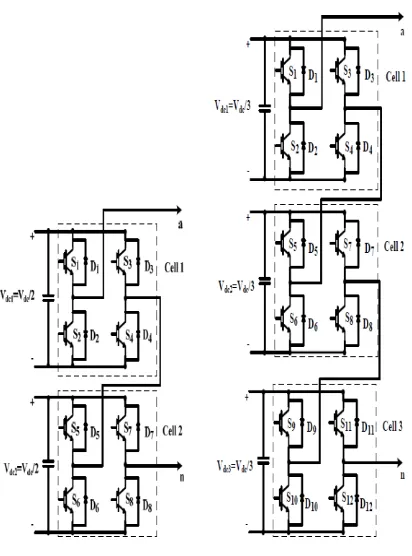
the cascade inverter, which can be synthesised by a series of single-phase full-bridge inverters. Assuming that the DC voltage of each full-bridge cell is same and equal to Vdc/2, each full-bridge inverter can switch between –Vdc,/2,0, and Vdc,/2. Therefore, by adding and subtracting of the output voltage levels of the two cascaded full-bridge inverter cells, five different voltage levels can be achieved in the output voltage. Switching states associated with different output voltage levels for the cascade inverter with two full-bridge inverter cells. Three-phase configuration can be easily implemented by three single-phase structures. Cascade configuration has been attracted for medium and high voltage renewable energy systems such as photovoltaic, due to its modular and simple structure. A higher level can easily be implemented by adding classical H-bridge cells in this configuration. However, it needs additional DC voltage sources and switching devices which can increase the cost of the system.
Fig -5: (a) Five –level and (b) Seven-level cascade Inverter
Advantages
Its active devices switching at (or nearly) the fundamental frequency, drastically reducing switching losses.
Elimination of the transformer in providing required voltage levels.
Easier packaging due to the simplicity of its structure and its low component-count.
5.HYSTERESIS METHOD
Fig -6:
Block Diagram
RECTIFIER
INVERTER
ARM
CONTROLLER
PULSE
WIDTH
MODULATO
R
MOT
OR
[image:4.595.300.558.304.632.2] [image:4.595.39.245.350.628.2]© 2016, IRJET |
Impact Factor
value
: 4.45|
ISO 9001:2008 Certified Journal | Page 563 5.1 Simulation Diagram
Fig -7:
Simulation Diagram
6. RESULT
The result were satisfactory and up to the expected level. This paper aims at intending an effective method to control the speed of the induction motor by using hysteresis method. The output can be obtained by using system interfaces and also dock light software is used to display the output. The output will be the frequency and time period. The speed can be changed step by step according to input sequence. The speed of the motor can be varied from 600 rpm to 1000 rpm.
7. CONCLUSION AND FUTURE WORK
To control the speed of a 3-phase induction motor in open loop, supply voltage and frequency need to be varied with constant ratio to each other. A low cost solution of this control can be implemented in ARM Processor. This requires three PWMs to control a 3-phase inverter bridge. Many ARM Processors have two hardware PWMs. The third PWM is generated in software and output to a port pin. Speed range of motor is 600 rpm to 1000 rpm.
The induction motor is run at 1000rpm to 600rpm.In future it will run at above 1000rpm by increasing the number of sequences.
8. REFERENCES
[1] J. Shao,” An improved microprocessor based sensor less brushless DC (BLDC) motor drive for automotive applications, ”IEEETrans.Ind.Appl.,Vol.42,no.5,pp.1216-1221,sep/oct 2010.
[2] J. Fang ,X. Zhou and G. Liu ,”Instantaneous torque control of small inductance brushless DC motor.” IEEE transactions.PowerElectron,vol.28,no.3,pp.1400-1412,Mar 2013.
[3] J. Fang, X. Zhou, and G. Liu, “Instantaneous torque control of small inductance brushless DC motor,” IEEE Trans. Power Electron., vol.27, no.12, pp.4952-4964, Dec. 2012.
[4] J. Su and J. W. Mc Keever, “Low-cost sensor less control of brushless DC motors with improved speed range,” IEEE Trans. Power Electron., vol.19, no.2, pp.296-302, Mar. 2004.
[5] D. H. Jung and I. J. Ha, “Low-cost sensor less control of brushless DC motors using a frequency-independent phase shifter,” IEEE Trans. Power Electron., vol.15, no.4, pp.744-752, July, 2000.
[6] R. C. Becerra, T. M. Jahns, and M. Ehsani, “Four-quadrant sensorless brushless ECM drive,” in Proc. IEEE- APEC’91 Conf., 1991, pp.202-209.
[image:5.595.42.284.138.441.2]