Programming the VeroPoint controller
2
1. Creating a new project:
1.1. Choose the database folder and set the project's path by using Main-Menu and clicking on the button.
1.2. Access Uniart\Bin and Run WinBAK_SBEx1.exe or hold left "Alt" button and click on the button.
1.3. In the database folder the following folders will be created automatically:
1.3.1. UWP – for Projects files. 1.3.2. UWF – for Program files
1.3.3. SuperBrain - for all SuperBrain/VeroPoint specials. In this folder the following sub folders will be created automatically:
1.3.3.1. bmp - for “.bmp” files as graphic display on the LCD screen. 1.3.3.2. obj – for internal use of the program. Includes “obj” files.
1.3.3.3. ALL_OBJ - for internal use of the program. Includes “.obj” files.
2. Establishing communication with VP (VeroPoint) controller:
2.1. Depends on the communication type (RS485 \ Ethernet TCP\IP) access
C:Uniart\Bin and activate Appserver.exe for RS485 or Netserve.exe for Ethernet. 2.2. Set the communication settings such as serial address, baud rate, parity and IP
address in the software to be similar as in the controller. (For more details please check the Uniart manual).
3
3. Programming the VeroPoint (VP) controller.
3.1. After running WinBAK_SBEx1 :
3.2. Select the project file you need, or create a new project file. 3.3. The following window will appear:
3.4. Use the Winbak functions in order to prepare the application you need according to the project requirements (for more details about using Winbak functions please check the Winbak manual).
4 IO descriptions and type
settings
5
3.6. To set the VeroPoint specials (HMI graphics and email) - press on the ” ” button.
IO
descriptions
Will be displayed on the controller's screen by pressing “help” button
Multilingual, make sure that the One Language is marked. Sets the program as a
“System A” only.
If checked, IO will be displayed in TEXT – table screen Value display, according to ”Display definitions” Enable Time Program for an Output
Sets a constant time program number for particular Output
6 3.7. Alarm settings:
Alarm descriptions
Multilingual, make sure that the One Language is marked.
An option to copy alarms text from WinBak. This will delete all existing alarms descriptions.
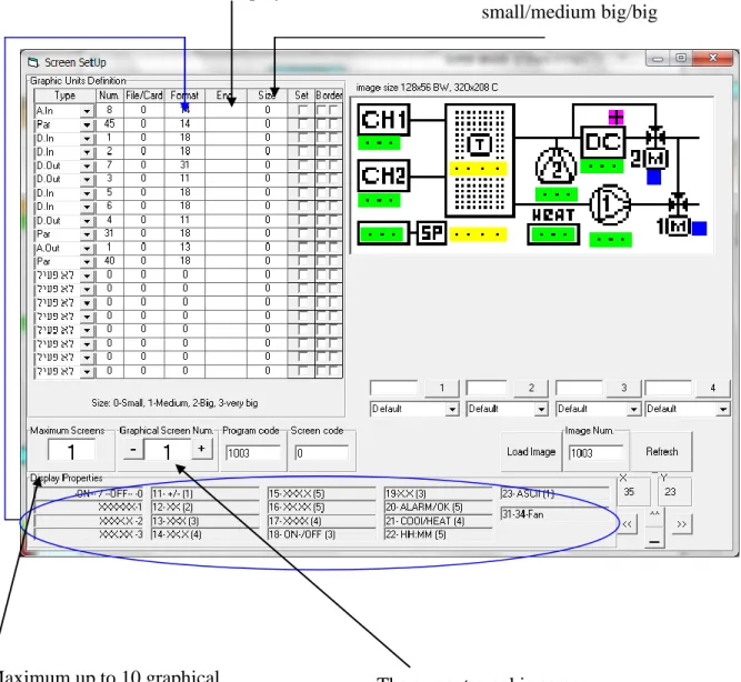
7 3.8. Graphic settings :
- Select type of control to display, the number (par# / Ain# / Dout# / etc…) and the format, according to display properties.
Place the point in the required location with the mouse. Use fine locating if necessary. Setting the program
ID number. Very important. Sets a bmp file as background for
graphic display. It refers to files stored in "bmp" folder, the files must have only number as their name.
8
3.9. Once finished saveby clicking on the save button . Engineering units.
Setting this, will blink
the value / Eng.-Units on the display.
Size of point:
0/1/2/3 = small/medium small/medium big/big
Maximum up to 10 graphical
9
4. Preparing email alarms for VeroPoint
4.1. Activate WinbakSB and open the relevant UWP project file.
4.2. Open the WinbakSB properties screen and press on the mail definition button.
01
4.4. This screen allows defining: email definitions, alarm message, according to the following explanation:
1) Use mail server - mark "v" in order to activate the email server in the VP. 2) Mail From – the text in this row is what the client will see as the name of
the email sender.
3) Mail to – the email address to send to.
4) Mail user – must be defined as in standard PC email definitions. 5) Mail password - must be defined as in standard PC email definitions. 6) Mail subject – the subject of the email message that the receiver will get
(free text).
7) Mail data lines 1,2,3 – the body of the message (free text).
00
9) Status ON, OFF – free text that can be applied to the subject or to the body of the message in cases of alarm is on or off (please check paragraph 12). 10) First Alarm, Last Alarm – the alarms number that will activate the email
messages (for example alarms from number 5-17).
11) Status, send off – mark "v" in cases that an email must be send also when the alarm is fixed.
12) Special signs and features:
a) %d – if used in the subject or body of the message will add the date of the alarm.
b) %t – if used in the subject or body of the message will add the time of the alarm.
c) %a – must be used in the subject or body of the message includes the description of the alarm as defined is SB.
d) %n – can be used in the subject or body of the message includes the description of the number alarm as defined is SB.
e) %i – used to mark end of line when using free text in the body of the message.
f) %s - can be used in the subject or body of the message includes the status messages as defined in paragraph 9.
02
5. Compiling and sending the program to controller.
5.1. Press on the compile button in WinBak .
SB Properties – links to graphical settings.
Compile – compiles the current project and creates an obj file in the obj folder without sending to the controller.
Send (All) – Sending all projects in the working folder to the controller (if One File Only is marked only current applications will be sent).
Communication COM number
on the computer that connected to the VeroPoint
Baud-rate and parity of the VeroPoint
VeroPoint Address (communication setting )
03 5.2. Sending new BIOS/Firmware.
Stretch the Send window, select the BIOS file (“Select File”) and send to controller (“Send BIOS to cpu”).
04
How to define Veropont extension cards in WinBAK
1. Hold ALT and click on in the left side menu in Uniart.
2. In the File Name field type the name of the file you want to create and click Open (make sure that a file with that name does not exist before clicking Open).
3. In the Projects View double click on IO
4. Click on the Type drop down box and select VeroPoint
5. Here you can define all of the IO points for the base unit.
05
7. The following window will appear
8. In the Description text field you can type in the description of the card. Right under it you can select whether the card is analog or digital, and then the appropriate IO list will become available.
9. In order to access the card IO points in the WinBAK software, there are some functions under the IO group which can be of use.
ExAin – to access an extension's analog input.
ExAout – to access an extension's analog output.
06
ExDout – to access an extension's digital output.
ExNDin – returns the opposite value of an extension's digital input (1 -> 0 0 -> 1)
ExRAout – returns the extension's analog output value.
ExRDout – returns the extension's digital output value.
10. Once you use one of these functions you'll be asked to choose the IO of the extension which you want to use.
How to assign a card number to an extension card
In Vero I/O go to Configuration, enter the password "1", go to UNIT-ID, and then choose the card number to assign (1-9).
In VeroDP go to Configuration, enter the password "1", go to Comm. Port, Address, and choose the card number to assign (1-9).
CANbus connection diagram
VeroPoint CANmux
Vero I/O VeroDP
RJ45 RJ45 RJ11 CAN 1 CAN CAN 1
07 VeroPoint
Vero I/O Vero I/O
RJ45 CAN 1
CAN 1
CAN 1 CAN 2 CAN 2
RJ45
RJ45