ETSI TS 103 737
V1.1.2
(2010-08)
Technical SpecificationSpeech and multimedia Transmission Quality (STQ);
Transmission requirements for narrowband wireless terminals
(handset and headset) from a QoS perspective
as perceived by the user
Reference
RTS/STQ-00166-1
Keywords
speech, terminal
ETSI
650 Route des Lucioles
F-06921 Sophia Antipolis Cedex - FRANCE Tel.: +33 4 92 94 42 00 Fax: +33 4 93 65 47 16
Siret N° 348 623 562 00017 - NAF 742 C Association à but non lucratif enregistrée à la
Sous-Préfecture de Grasse (06) N° 7803/88
Important notice
Individual copies of the present document can be downloaded from:
http://www.etsi.org
The present document may be made available in more than one electronic version or in print. In any case of existing or perceived difference in contents between such versions, the reference version is the Portable Document Format (PDF). In case of dispute, the reference shall be the printing on ETSI printers of the PDF version kept on a specific network drive
within ETSI Secretariat.
Users of the present document should be aware that the document may be subject to revision or change of status. Information on the current status of this and other ETSI documents is available at
http://portal.etsi.org/tb/status/status.asp
If you find errors in the present document, please send your comment to one of the following services:
http://portal.etsi.org/chaircor/ETSI_support.asp
Copyright Notification
No part may be reproduced except as authorized by written permission. The copyright and the foregoing restriction extend to reproduction in all media.
© European Telecommunications Standards Institute 2010. All rights reserved.
DECTTM, PLUGTESTSTM, UMTSTM, TIPHONTM, the TIPHON logo and the ETSI logo are Trade Marks of ETSI registered for the benefit of its Members.
3GPPTM is a Trade Mark of ETSI registered for the benefit of its Members and of the 3GPP Organizational Partners.
Contents
Intellectual Property Rights ... 5
Foreword ... 5
Introduction ... 5
1 Scope
... 6
2 References
... 6
2.1 Normative references ... 6 2.2 Informative references ... 73 Definitions
and
abbreviations
... 8
3.1 Definitions ... 8
3.2 Abbreviations ... 8
4 Configurations
and interfaces ... 9
4.1 Access networks ... 9
4.2 Additional (radio) links between the terminal and external electroacoustical devices ... 9
5 Test
Configurations ... 9
5.1 Set-up interface ... 9
5.2 Set-up for terminals ... 10
5.3 Acoustical environment ... 10
5.4 Test signals ... 11
5.5 Calibration ... 11
5.6 Environmental conditions for tests ... 12
5.7 Accuracy of test equipment ... 13
5.8 Power feeding ... 13
5.9 Influence of terminal delay on measurements ... 13
6
Codec independent requirements and associated Measurement Methodologies ... 13
6.1 Send and receive frequency response ... 13
6.1.1 Send frequency response ... 13
6.1.2 Receive frequency response ... 15
6.2 Send and receive loudness ratings ... 18
6.2.1 Send Loudness Rating (SLR)... 18
6.2.2 Receive Loudness Rating (RLR) ... 18
6.2.3 LR stability ... 19
6.3 Sidetone parameters ... 19
6.3.1 SideTone Masking Rating (STMR) ... 19
6.3.2 Sidetone delay ... 19
6.3.3 D-factor ... 20
6.4 Send and receive noise ... 20
6.4.1 Send noise ... 20
6.4.2 Receive noise ... 21
6.5 Send and receive distortion ... 21
6.5.1 Send Distortion ... 21
6.5.2 Receive distortion ... 22
6.6 Stability loss and TCLw ... 22
6.6.1 Stability loss... 22
6.6.2 TCLw (or similar parameters) ... 23
6.7 Double talk performance ... 24
6.7.1 Attenuation Range in Send Direction during Double Talk AH,S,dt... 24
6.7.2 Attenuation Range in Receive Direction during Double Talk AH,R,dt ... 26
6.7.3 Detection of echo components during double Talk ... 27
6.7.4 Minimum activation level and sensitivity of double talk detection ... 28
6.8 Switching parameters ... 29
6.8.1 Activation in Send Direction ... 29
6.8.3 Automatic level control ... 30
6.8.4 Silence Suppression and Comfort Noise Generation ... 30
6.9 Background noise performance ... 30
6.9.1 Performance in send direction in the presence of background noise ... 30
6.9.2 Speech Quality in the Presence of Background Noise ... 31
6.9.3 Quality of Background Noise Transmission (with Far End Speech) ... 32
6.9.4 Quality of Background Noise Transmission (with Near End Speech) ... 32
6.10 Quality of echo cancellation ... 33
6.10.1 Temporal echo effects ... 33
6.10.2 Spectral Echo Attenuation ... 33
6.10.3 Occurrence of Artifacts ... 34
6.11 Send and receive delay - Round trip delay ... 34
6.12 Objective listening Quality in send and receive direction ... 35
7
Codec dependent requirements and associated Measurement Methodologies ... 36
7.1 Speech Coders ... 36
7.2 Send and receive delay or round trip delay ... 36
7.3 Objective listening Quality in send and receive direction ... 36
8
Requirements and associated Measurement Methodologies (with an additional radio link between
the terminal and external electroacoustical devices) ... 36
Annex A (informative):
D-Factor ... 37
Annex B (informative):
Bibliography ... 38
Intellectual Property Rights
IPRs essential or potentially essential to the present document may have been declared to ETSI. The information pertaining to these essential IPRs, if any, is publicly available for ETSI members and non-members, and can be found in ETSI SR 000 314: "Intellectual Property Rights (IPRs); Essential, or potentially Essential, IPRs notified to ETSI in respect of ETSI standards", which is available from the ETSI Secretariat. Latest updates are available on the ETSI Web server (http://webapp.etsi.org/IPR/home.asp).
Pursuant to the ETSI IPR Policy, no investigation, including IPR searches, has been carried out by ETSI. No guarantee can be given as to the existence of other IPRs not referenced in ETSI SR 000 314 (or the updates on the ETSI Web server) which are, or may be, or may become, essential to the present document.
Foreword
This Technical Specification (TS) has been produced by ETSI Technical Committee Speech and multimedia Transmission Quality (STQ).
Introduction
The present document covers wireless speech terminals. It aims to enhance the interoperability and end-to-end quality with all other types of terminals.
1 Scope
The present document provides speech transmission performance requirements for wireless terminals; it addresses all types of wireless terminals, including softphones. This part addresses handset and headset functions of narrow-band wireless terminals.
In contrast to other standards which define minimum performance requirements it is the intention of the present
document to specify terminal equipment requirements which enable manufacturers and service providers to enable good quality end-to-end speech performance as perceived by the user, whatever be the radio link (terminals may implement different radio links with the access network).
When an additional radio link between the terminal and external electroacoustical devices is used (e.g. Bluetooth link), the standard will address the overall quality
In the present document objective measurement methodologies and requirements for wireless speech terminals are given.
In addition to basic testing procedures, the present document describes advanced testing procedures taking into account further quality parameters as perceived by the user.
The requirements available in the present document will ensure a high compatibility across access networks with all types of terminals.
It is the aim to optimize the listening and talking quality, conversational performance, as well as the use in noisy environment. Related requirements and test methods will be defined in the present document.
For all the functions, the standard will consider the limitations in audio performance due to different form factors (e.g. size, shape).
Terminals which are not intended to be connected to public networks are outside the scope of the present document.
2 References
References are either specific (identified by date of publication and/or edition number or version number) or
non-specific. For specific references, only the cited version applies. For non-specific references, the latest version of the reference document (including any amendments) applies.
Referenced documents which are not found to be publicly available in the expected location might be found at http://docbox.etsi.org/Reference.
NOTE: While any hyperlinks included in this clause were valid at the time of publication ETSI cannot guarantee their long term validity.
2.1 Normative
references
The following referenced documents are necessary for the application of the present document. [1] ITU-T Recommendation P.50: "Artificial voices".
[2] ITU-T Recommendation P.56: "Objective measurement of active speech level". [3] ITU-T Recommendation P.57: "Artificial ears".
[4] ITU-T Recommendation P.58: "Head and torso simulator for telephonometry".
[5] ITU-T Recommendation P.64: "Determination of sensitivity/frequency characteristics of local telephone systems".
[7] ITU-T Recommendation P.310: "Transmission characteristics for telephone band (300-3400 Hz) digital telephones".
[8] ITU-T Recommendation P.340: "Transmission characteristics and speech quality parameters of hands-free terminals".
[9] ITU-T Recommendation P.380: "Electro-acoustic measurements on headsets". [10] ITU-T Recommendation P.501: "Test signals for use in telephonometry".
[11] ITU-T Recommendation P.502: "Objective test methods for speech communication systems using complex test signals".
[12] ITU-T Recommendation P.581: "Use of head and torso simulator (HATS) for hands-free terminal testing".
[13] ITU-T Recommendation G.122: "Influence of national systems on stability and talker echo in international connections".
[14] IEC 61260: "Electroacoustics - Octave-band and fractional-octave-band filters". [15] ISO 3 (1973): "Preferred numbers - Series of preferred numbers".
[16] IEC 61672-1: "Electroacoustics - Sound level meters - Part 1: Specifications".
[17] ETSI TS 126 171: " Digital cellular telecommunications system (Phase 2+); Universal Mobile Telecommunications System (UMTS); AMR speech codec, wideband; General description (3GPP TS 26.171 version 6.0.0 Release 6)" .
[18] ITU-T Recommendation G.729.1: "G.729 based Embedded Variable bit-rate coder: An 8-32 kbit/s scalable wideband coder bitstream interoperable with G.729".
[19] ITU-T Recommendation G.711: "Pulse code modulation (PCM) of voice frequencies". [20] ITU-T Recommendation G.726: "40, 32, 24, 16 kbit/s Adaptive Differential Pulse Code
Modulation (ADPCM)".
[21] ITU-T Recommendation G.729: "Coding of speech at 8 kbit/s using conjugate-structure algebraic-code-excited linear prediction (CS-ACELP)".
[22] ETSI TS 146 060: "Digital cellular telecommunications system (Phase 2+); Enhanced Full Rate (EFR) speech transcoding (3GPP TS 46.060)".
[23] ETSI TS 146 010: "Digital cellular telecommunications system (Phase 2+); Full-rate speech; Transcoding (3GPP TS 46.010)".
2.2 Informative
references
The following referenced documents are not necessary for the application of the present document but they assist the user with regard to a particular subject area.
[i.1] ETSI EG 202 396-1: "Speech and multimedia Transmission Quality (STQ); Speech quality performance in the presence of background noise; Part 1: Background noise simulation technique and background noise database".
[i.2] ETSI EG 202 396-3: "Speech Processing, Transmission and Quality Aspects (STQ); Speech Quality performance in the presence of background noise Part 3: Background noise transmission - Objective test methods".
3 Definitions
and
abbreviations
3.1 Definitions
For the purposes of the present document, the following terms and definitions apply:
artificial ear: device for the calibration of earphones incorporating an acoustic coupler and a calibrated microphone for the measurement of the sound pressure and having an overall acoustic impedance similar to that of the median adult human ear over a given frequency band
codec: combination of an analogue-to-digital encoder and a digital-to-analogue decoder operating in opposite directions of transmission in the same equipment
diffuse field equalization: equalization of the HATS sound pick-up, equalization of the difference, in dB, between the spectrum level of the acoustic pressure at the ear Drum Reference Point (DRP) and the spectrum level of the acoustic pressure at the HATS Reference Point (HRP) in a diffuse sound field with the HATS absent by applying the reverse nominal curve of table 3 of ITU-T Recommendation P.58 [4]
echo loss: semi-loop loss averaged with 1/f power weighting over the telephone band, in accordance with ITU-T Recommendation G.122 [13], clause 4
Head And Torso Simulator (HATS) for telephonometry: manikin extending downward from the top of the head to the waist, designed to simulate the sound pick-up characteristics and the acoustic diffraction produced by a median human adult and to reproduce the acoustic field generated by the human mouth
Mouth Reference Point (MRP): is located on axis and 25 mm in front of the lip plane of a mouth simulator
nominal setting of the volume control: when a receive volume control is provided, the setting which is closest to the nominal RLR of 2 dB
3.2 Abbreviations
For the purposes of the present document, the following abbreviations apply: CDMA Code Division Multiple Access
CSS Composite Source Signal
D D-Value of Terminal
DECT Digital Enhanced Cordless Telecommunications DRP ear Drum Reference Point
EL Echo Loss
ERP Ear Reference Point
G-MOS Global mean opinion score
GSM Global Service for Mobile communication HATS Head And Torso Simulator
HRP HATS Reference Point
LQOw listening quality, objective, wideband
MRP Mouth Reference Point
N-MOS Noise mean opinion score
PLC Packet Loss Concealment
POI Point Of Interconnect
QoS Quality of Service
RLR Receive Loudness Rating
SLR Send Loudness Rating
S-MOS Speech mean opinion score STMR SideTone Masking Rating
TCLw Terminal Coupling Loss (weighted)
UMTS Universal Mobile Telecommunications System
WIFI Wireless Fidelity
4 Configurations
and
interfaces
The present document is intended to be applicable for different wireless access networks and for additional radio links.
4.1 Access
networks
The present document applies to any wireless terminal whatever the network access, e.g. GSM, UMTS, DECT, Bluetooth, WIFI, WIMAX, CDMA.
4.2
Additional (radio) links between the terminal and external
electroacoustical devices
The whole terminal may include additional (radio) links. The most of the requirements and test methods apply to the whole terminal. When specific requirements or test methods are needed, they can be found in clause 8.
5 Test
Configurations
5.1
Set-up interface
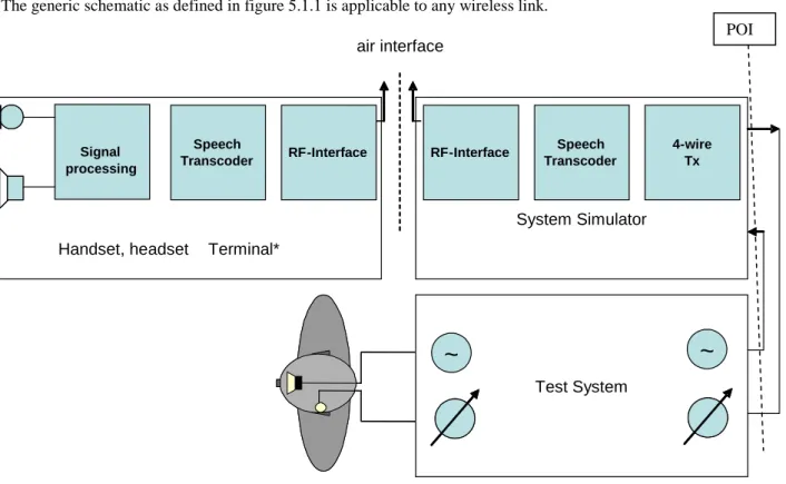
The generic schematic as defined in figure 5.1.1 is applicable to any wireless link.
NOTE: The "whole" terminal includes all the components from "RF interface" to the transducers and may include an additional (radio) link. The air interface considered in the figure is not the additional radio link.
Figure 5.1.1: Set-up interface Handset, headset Terminal*
System Simulator Signal processing RF- Interface Speech Transcoder RF-Interface 4- wire Tx Test System
~
~
air interface Speech Transcoder POI5.2
Set-up for terminals
The acoustical access to terminals is the most realistic simulation of the "average" subscriber. This can be made by using HATS (Head And Torso Simulator) with appropriate ear simulation and appropriate means to fix handset and headset terminals in a realistic and reproducible way to the HATS. HATS is described in ITU-T Recommendation P.58 [4], appropriate ears are described in ITU-T Recommendation P.57 [3] (type 3.3 and type 3.4 ear), a proper positioning of handsets under realistic conditions is to be found in ITU-T Recommendation P.64 [5].
The preferred way of testing a terminal is to connect it to a network simulator with exact defined settings and access points. The test sequences are fed in either electrically, using a reference codec or using the direct signal processing approach and acoustically using ITU-T HATS.
When a coder with variable bit rate is used for testing terminal electroacoustical parameters, the bit rate giving the best characteristics or the most commonly used should be selected, e.g.:
• AMR-NB (TS 126 171 [17]): 12,2 kbit/s; • ITU-T Recommendation G.729.1 [18]: 32 kbit/s. Setup for handsets and headsets
When using a handset telephone the handset is placed in the HATS position as described in ITU-T Recommendation P.64 [5]. The artificial mouth shall be conform with ITU-T Recommendation P.58 [4]. The artificial ear shall be conform with ITU-T Recommendation P.57 [3], type 3.3 or type 3.4 ears shall be used.
Recommendations for positioning headsets are given in ITU-T Recommendation P.380 [9]. If not stated otherwise headsets shall be placed in their recommended wearing position. Further information about setup and the use of HATS can be found in ITU-T Recommendation P.380 [9].
Unless stated otherwise if a volume control is provided the setting is chosen such that the nominal RLR is met as close as possible.
Unless stated otherwise, the application force of 8 N is used for handset testing. No application force is used for headset.
5.3 Acoustical
environment
In general different acoustical environments have to be taken into account: either room noise and background noise are an inherent part of the test environment or room noise and background noise shall be eliminated to such an extent that their influence on the test results can be neglected.
Unless stated otherwise, measurements shall be conducted under quiet and "anechoic" conditions.
Considering this, test laboratory, in the case where its test room does not conform to anechoic conditions as given in ITU-T Recommendation P.310 [7], has to present difference in results for measurements due to its test room. In case where an anechoic room is not available the test room has to be an acoustically treated room with few reflections and a low noise level.
Depending on the distance of the transducers from mouth to ear a quiet office room may be sufficient e.g. for handsets where artificial mouth and artificial ear are located close to the acoustical transducers.
However, for some headsets or handset terminals with smaller dimension an anechoic room will be required. In cases where real or simulated background noise is used as part of the testing environment, the original background noise must not be noticeably influenced by the acoustical properties of the room.
In all cases where the performance of acoustic echo cancellers shall be tested a realistic room which represents the typical user environment for the terminal shall be used.
5.4 Test
signals
Due to the coding of the speech signals, care should be taken when using single frequency for wireless terminals/networks (e.g. GSM/3G) acoustic tests. Appropriate test signals (general description) are defined in
ITU-T Recommendations P.50 [1] and P.501 [10]. Normative requirements for the use of test signals from P.501 are for further study.
More information can be found in the test procedures described below.
For testing the narrow-band telephony service provided by a terminal the test signal used shall be band limited between 100 Hz and 4 kHz with a bandpass filter providing a minimum of 24 dB/Oct. filter roll off, when feeding into the receive direction.
Unless specified otherwise, the test signal levels are referred to the average level of the (band limited in receive direction) test signal, averaged over the complete test sequence .
Unless specified otherwise, the test signal level shall be -4,7 dBPa at the MRP.
Unless specified otherwise, the applied test signal level at the digital input shall be -16 dBm0.
5.5 Calibration
Position and calibration of HATS
All the send and receive characteristics shall be tested with the HATS, it shall be indicated what type of ear was used at what application force. For handsets if not stated otherwise 8N application force shall be used.
The horizontal positioning of the HATS reference plane shall be guaranteed within ±2º.
The HATS shall be equipped with a type 3.3 or type 3.4 artificial ear for handsets. For binaural headsets two artificial ears are required. The type 3.3 or type 3.4 artificial ears as specified in Recommendation P.57 [3] shall be used. The artificial ear shall be positioned on HATS according to ITU-T Recommendation P.58 [4].
The exact calibration and equalization can be found in ITU-T Recommendation P.581 [12]. If not stated otherwise, the HATS shall be diffuse-field equalized. The inverse nominal diffuse field curve as found in table 3 of ITU-T
Recommendation P.58 [4] shall be used.
Note: The inverse average diffuse field response characteristics of HATS as found in P. 58 is used and not the specific one corresponding to the HATS used. Instead of using the individual diffuse field correction, the average correction function is used because, for handset and headset measurements, mostly the artificial ear, ear canal and ear impedance simulations are effective. The individual diffuse-field correction function of HATS includes all diffraction and reflection effects of the complete individual HATS which are not effective in the measurement and potentially would lead to bigger measurement uncertainties than using the average correction.
Setup of background noise simulation
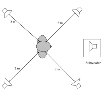
A setup for simulating realistic background noises in a lab-type environment is described in EG 202 396-1 [i.1]. EG 202 396-1 [i.1] contains a description of the recording arrangement for realistic background noises, a description of the setup for a loudspeaker arrangement suitable to simulate a background noise field in a lab-type environment and a database of realistic background noises, which can be used for testing the terminal performance with a variety of different background noises.
2 m 2 m
Subwoofer 2 m
2 m
Figure 5.5.1: Loudspeaker arrangement for background noise simulation The equalization and calibration procedure for the setup is described in detail in EG 202 396-1 [i.1].
If not stated otherwise this setup is used in all measurements where background noise simulation is required. The following noises EG 202 396-1 [i.1] in table 5.5.1 shall be used.
Table 5.5.1: Noises used for background noise simulation
Recording in pub Pub_Noise_binaural 30 s L: 77,8 dB(A)
R: 78,9 dB(A) binaural Recording at sales counter Cafeteria_Noise_binaural 30 s L: 68,4 dB(A)
R: 67,3 dB(A) binaural Recording in business office Work_Noise_Office_Callcener_binaural 30 s L: 56,6 dB(A)
R: 57,8 dB(A) binaural
5.6
Environmental conditions for tests
The following conditions shall apply for the testing environment: a) Ambient temperature: 15 °C to 35 °C (inclusive); b) Relative humidity: 5 % to 85 %;
5.7
Accuracy of test equipment
Unless specified otherwise, the accuracy of measurements made by test equipment shall be better than: Table 5.7.1: Accuracy of measurements
Item Accuracy
Electrical Signal Power Electrical Signal Power
Sound pressure Time Frequency Application force Measured maximum frequency
±0,2 dB for levels ≥ -50 dBm ±0,4 dB for levels < -50 dBm ±0,7 dB ±0,2 % ±0,2 % ±2 Newton 10 kHz NOTE: The measured maximum frequency is due to P.58 [4] limitations.
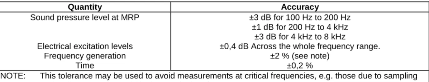
Unless specified otherwise, the accuracy of the signals generated by the test equipment shall be better than: Table 5.7.2: Accuracy of generated signals
Quantity Accuracy
Sound pressure level at MRP
Electrical excitation levels Frequency generation
Time
±3 dB for 100 Hz to 200 Hz ±1 dB for 200 Hz to 4 kHz
±3 dB for 4 kHz to 8 kHz
±0,4 dB Across the whole frequency range. ±2 % (see note)
±0,2 %
NOTE: This tolerance may be used to avoid measurements at critical frequencies, e.g. those due to sampling and coding operations within the terminal under test.
The measurements results shall be corrected for the measured deviations from the nominal level. The sound level measurement equipment shall conform to IEC 61672-1 [16] Type 1.
5.8 Power
feeding
For terminal equipment which is directly powered from the mains supply, all tests shall be carried out within ±5 % of the rated voltage of that supply. If the equipment is powered by other means and those means are not supplied as part of the apparatus, all tests shall be carried out within the power supply limit declared by the supplier. If the power supply is a.c., the test shall be conducted within ±4 % of the rated frequency.
5.9
Influence of terminal delay on measurements
As delay is introduced by the terminal, care shall be taken for all measurements where exact position of the analysis window is required. It shall be checked that the test is performed on the test signal and not any other signal.
6
Codec independent requirements and associated
Measurement Methodologies
6.1
Send and receive frequency response
6.1.1 Send
frequency
response
Requirement
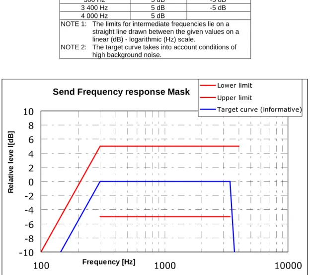
The send frequency response of the handset or the headset shall be within a mask as defined in table 6.1.1.1 and shown in figure 6.1.1.1. This mask shall be applicable for all types of handsets and headsets.
Table 6.1.1.1: Send frequency response
Frequency Upper Limit Lower Limit
100 Hz -10 dB (note 2) 300 Hz 5 dB -5 dB 3 400 Hz 5 dB -5 dB 4 000 Hz 5 dB
NOTE 1: The limits for intermediate frequencies lie on a straight line drawn between the given values on a linear (dB) - logarithmic (Hz) scale.
NOTE 2: The target curve takes into account conditions of high background noise.
Send Frequency response Mask
-10
-8
-6
-4
-2
0
2
4
6
8
10
100
Frequency [Hz]1000
10000
R e la ti v e le v e l[ d B ]Lower limit
Upper limit
Target curve (informative)
Figure 6.1.1.1: Send frequency response mask
NOTE: The basis for the target frequency responses in send and receive is the orthotelefonic reference response which is measured between 2 subjects in 1 m distance under free field conditions and is assuming an ideal receive characteristic. Under these conditions the overall frequency response shows a rising slope. In opposite to other standards the present document no longer uses the ERP as the reference point for receive but the diffuse-field. With the concept of diffuse-field based receive measurements a rising slope for the overall frequency response is achieved by a flat target frequency response in send and a flat diffuse-field based receive frequency response.
Test method
The test signal to be used for the measurements shall be the artificial voice according to ITU-Recommendation P. 50 [1] or a speech like test signal as described in ITU-T Recommendation P.501 [10]. The type of test signal used shall be stated in the test report. The spectrum of acoustic signal produced by the artificial mouth is calibrated under free field conditions at the MRP. The test signal level shall be -4,7 dBPa, measured at the MRP. The test signal level is averaged over the complete test signal sequence.
The handset or headset terminal is setup as described in clause 5.2. The handset is mounted at the HATS position (see ITU-T Recommendation P.64 [5]). The application force used to apply the handset against the artificial ear shall be within the range specified in ITU-T Recommendation P.64 [5].
Measurements shall be made at one twelfth-octave intervals as given by the R.40 series of preferred numbers in ISO 3 [15] for frequencies from 100 Hz to 4 kHz inclusive. For the calculation the averaged measured level at the electrical reference point for each frequency band is referred to the averaged test signal level measured in each frequency band at the MRP.
The sensitivity is expressed in terms of dBV/Pa.
6.1.2
Receive frequency response
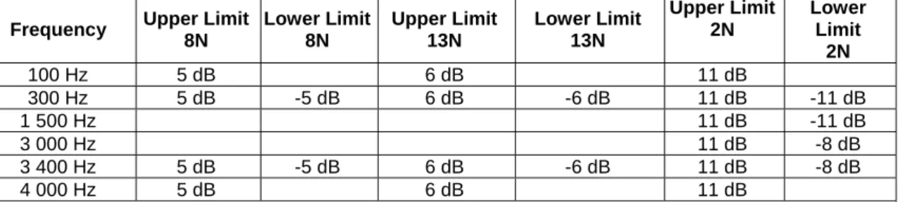
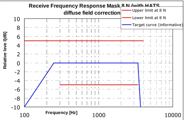
RequirementThe receive frequency response of the handset or the headset shall be within a mask as defined in table 6.1.2.1 and shown in figures 6.1.2.1 to 6.1.2.3. The application force for handsets is 2N, 8N and 13N. The mask defined for 8 N application force shall be applicable for all types of headsets.
Table 6.1.2.1: Receive Frequency Response Mask
Frequency Upper Limit 8N Lower Limit 8N Upper Limit 13N Lower Limit 13N Upper Limit 2N Lower Limit 2N 100 Hz 5 dB 6 dB 11 dB 300 Hz 5 dB -5 dB 6 dB -6 dB 11 dB -11 dB 1 500 Hz 11 dB -11 dB 3 000 Hz 11 dB -8 dB 3 400 Hz 5 dB -5 dB 6 dB -6 dB 11 dB -8 dB 4 000 Hz 5 dB 6 dB 11 dB
NOTE 1: The limit curves shall be determined by straight lines joining successive co-ordinates given in the table, where frequency response is plotted on a linear dB scale against frequency on a logarithmic scale. is a floating or 'best fit' mask.
NOTE 2: The basis for the target frequency responses in send and receive is the orthotelefonic reference response which is measured between 2 subjects in 1 m distance under free field conditions and is assuming an ideal receive characteristic. This flat response characteristics is shown as the target curve. Under these conditions the overall frequency response shows a rising slope. In opposite to other standards the present document no longer uses the ERP as the reference point for receive but the diffuse field. With the concept of diffuse-field based receive measurements a rising slope for the overall frequency response is achieved by a flat target frequency response in send and a flat diffuse field based receive frequency response.
NOTE 3: With current technology it may be difficult or even not possible to achieve the desired frequency response characteristics for handsets with 2N application force.
Receive Frequency Response Mask 8 N (with HATS
diffuse field corrections)
-10
-8
-6
-4
-2
0
2
4
6
8
10
100
Frequency [Hz]1000
10000
R e la ti ve l eve l [d B ]Upper limit at 8 N
Lower limit at 8 N
Target curve (informative)
Figure 6.1.2.1: Receive frequency response mask for 8N application force
Receive Frequency Response Mask 13 N (with HATS
diffuse field corrections)
-10
-8
-6
-4
-2
0
2
4
6
8
10
100
Frequency [Hz]1000
10000
R e la ti v e le v e l[ d B ]Upper limit at 13 N
Lower limit at 13 N
Target curve (informative)
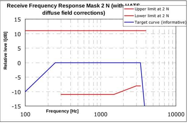
Receive Frequency Response Mask 2 N (with HATS
diffuse field corrections)
-15
-10
-5
0
5
10
15
100
Frequency [Hz]1000
10000
R e la ti v e le v e l[ d B ]Upper limit at 2 N
Lower limit at 2 N
Target curve (informative)
Figure 6.1.2.3: Receive frequency response mask for 2N application force Test method
Receive frequency response is the ratio of the measured sound pressure and the input level. (dB relative Pa/V)
SJeff = 20 log (peff / vRCV) dB rel 1 Pa / V (1) SJeff Receive Sensitivity; Junction to HATS Ear with diffuse field correction.
peff DRP Sound pressure measured by ear simulator Measurement data are converted from the Drum Reference Point to diffuse field.
vRCV Equivalent RMS input voltage.
The test signal to be used for the measurements shall be the artificial voice according to ITU-T Recommendation P.50 [1], duration 20 s (10 s female, 10 s male voice). The test signal level shall be -16 dBm0, measured according to ITU-T Recommendation P.56 [2] at the digital reference point or the equivalent analogue point.
The handset terminal or the headset terminal is setup as described in clause 5.2. The handset is mounted in the HATS position (see ITU-T Recommendation P.64 [5]). The application forces used to apply the handset against the artificial ear is 2N, 8N and 13N.
In case of headset measurements the tests are repeated 5 times, in conformance with ITU-T Recommendation P.380 [9] the results are averaged (averaged value in dB, for each frequency).
The HATS is diffuse-field equalized. The equalized output signal is power-averaged on the total time of analysis. The 1/12 octave band data are considered as the input signal to be used for calculations or measurements.
Measurements shall be made at one twelfth-octave intervals as given by the R.40 series of preferred numbers in ISO 3 [15] for frequencies from 100 Hz to 4 kHz inclusive. For the calculation the averaged measured level at each frequency band is referred to the averaged test signal level measured in each frequency band.
6.2
Send and receive loudness ratings
6.2.1
Send Loudness Rating (SLR)
RequirementThe nominal value of Send Loudness Rating (SLR) shall be:
SLR(set) = +8 dB ± 3 dB (2)
Measurement Method
The test signal to be used for the measurements shall be the artificial voice according to ITU-T Recommendation P.50 [1], duration 20 s (10 s female, 10 s male voice). The spectrum of acoustic signal produced by the artificial mouth is calibrated under free field conditions at the MRP. The test signal level shall be -4,7 dBPa, measured at the MRP. The test signal level is averaged over the complete test signal sequence.
The handset or headset terminal is setup as described in clause 5.2. The handset is mounted in the HATS position (see ITU-T Recommendation P.64 [5]). The application force used to apply the handset against the artificial ear is noted in the test report.
In case of headset measurements the tests are repeated 5 times, in conformance with ITU-T Recommendation P.380 [9] the results are averaged (averaged value in dB, for each frequency).
The send sensitivity shall be calculated from each band of the 14 frequencies given in table 1 of ITU-T
Recommendation P.79 [6], bands 4 to 17. For the calculation the averaged measured level at the electrical reference point for each frequency band is referred to the averaged test signal level measured in each frequency band at the MRP. The sensitivity is expressed in terms of dBV/Pa and the SLR shall be calculated according to ITU-T Recommendation P.79 [6], formula 5-1, over bands 4 to 17, using m = 0,175 and the send weighting factors from ITU-T Recommendation P.79 [6], table 1.
6.2.2
Receive Loudness Rating (RLR)
The nominal value of Receive Loudness Rating (RLR) for handset and monaural headset shall be:
RLR = +2 ± 3 dB (3)
Where a user controlled receive volume control is provided, the RLR shall meet the selected nominal value for at least one setting of the control. When the control is set to maximum, the RLR shall not be less than (louder than) -13 dB. With the volume control set to the minimum position the RLR shall not be greater than (quieter than) 18 dB. For Binaural headset:
RLR (binaural headset) = +8 dB ± 3 dB for each earphone (4) Measurement Method
The test signal to be used for the measurements shall be the artificial voice according to ITU-T Recommendation P.50 [1], duration 20 s (10 s female, 10 s male voice). The test signal level shall be -16 dBm0, measured at the digital reference point or the equivalent analogue point. The test signal level is averaged over the complete test signal sequence.
The handset or headset terminal is setup as described in clause 5.2. The handset is mounted in the HATS position (see ITU-T Recommendation P.64 [5]). The application force used to apply the handset against the artificial ear is noted in the test report. The HATS is NOT diffuse-field equalized. The DRP-ERP correction as defined in ITU-T
Recommendation P.57 [3] is applied.
The application force used to apply the handset against the artificial ear is noted in the test report. By default, 8N will be used.
The receive sensitivity shall be calculated from each band of the 14 frequencies given in table 1 of ITU-T
Recommendation P.79 [6], bands 4 to 17. For the calculation the averaged measured level at each frequency band is referred to the averaged test signal level measured in each frequency band.
The sensitivity is expressed in terms of dBPa/V and the RLR shall be calculated according to ITU-T Recommendation P.79 [6], formula 5-1, over bands 4 to 17, using m = 0,175 and the receive weighting factors from table 1 of ITU-T Recommendation P.79 [6]. No leakage correction shall be applied for the measurement.
6.2.3
LR stability
For further studies.6.3 Sidetone
parameters
The present document covers different types of terminals and different use cases (including noisy environments). STMR requirements are basically defined when using terminals in low noise environments.
6.3.1 SideTone
Masking
Rating
(STMR)
Requirement
The SideTone Masking Rating STMR shall be 16 dB ± 4 dB for nominal setting of the volume control. For all other positions of the volume control, the STMR must not be below 8 dB.
NOTE: It is preferable to have a constant STMR independent of the volume control setting. Measurement Method
The test signal to be used for the measurements shall be the artificial voice according to ITU-T Recommendation P.50 [1]. The spectrum of the acoustic signal produced by the artificial mouth is calibrated under free field conditions at the MRP. The test signal level shall be -4,7 dBPa, measured at the MRP. The test signal level is averaged over the complete test signal sequence.
The handset or headset terminal is setup as described in clause 5.2. The handset is mounted in the HATS position (see ITU-T Recommendation P.64 [5]) and the application force shall be 13N on the artificial ear type 3.3 or type 3.4. Where a user operated volume control is provided, the measurements shall be carried out at the nominal setting of the volume control. In addition the measurement is repeated at the maximum volume control setting.
Measurements shall be made at one twelfth-octave intervals as given by the R.40 series of preferred numbers in ISO 3 [15] for frequencies from 100 Hz to 8 kHz inclusive. For the calculation the averaged measured level at each frequency band (ITU-T Recommendation P.79 [6], table 3, bands 1 to 20) is referred to the averaged test signal level measured in each frequency band.
The Sidetone path loss (LmeST), as expressed in dB, and the SideTone Masking Rate (STMR) (in dB) shall be calculated from the formula 5-1 of ITU-T Recommendation P.79 [6], using m = 0,225 and the weighting factors of in table 3 of ITU-T Recommendation P.79 [6].
6.3.2 Sidetone
delay
Requirement
The maximum sidetone-round-trip delay shall be ≤ 5 ms, measured in an echo-free setup. Measurement Method
The handset or headset terminal is setup as described in clause 5.2. The handset is mounted in the HATS position (see ITU-T Recommendation P.64 [5]).
The test signal is a CS-signal complying with ITU-T Recommendation P.501 [10] using a pn sequence with a length of 4 096 points (for the 48 kHz sampling rate) which equals to the period T. The duration of the complete test signal is as specified in ITU-T Recommendation P.501 [10]. The level of the signal shall be -4,7 dBPa at the MRP.
The cross-correlation function Φxy(τ) between the input signal Sx(t) generated by the test system in send direction and the output signal Sy(t) measured at the artificial ear is calculated in the time domain:
)
(
)
(
1
)
(
2 2τ
τ
=
⋅
+
Φ
∫
− =t
S
t
S
T
y T T t x xy (5)The measurement window T shall be exactly identical with the time period T of the test signal, the measurement window is positioned to the pn-sequence of the test signal.
The sidetone delay is calculated from the envelope E(τ) of the cross-correlation function Φxy(τ). The first maximum of the envelope function occurs in correspondence with the direct sound produced by the artificial mouth, the second one occurs with a possible delayed sidetone signal. The difference between the two maxima corresponds to the sidetone delay. The envelope E(τ) is calculated by the Hilbert transformation H {xy(τ)} of the cross-correlation:
{
}
∑
+∞ −∞ =−
Φ
=
u xyu
u
xy
H
)
(
)
(
)
(
τ
π
τ
(6)[
]
2[
{
}
]
2)
(
)
(
)
(
τ
τ
H
xy
τ
E
=
Φ
xy+
(7)It is assumed that the measured sidetone delay is less than T/2.
6.3.3 D-factor
Due to the highly sophisticated speech processing technics (e.g. noise cancellation) introduced in wireless terminals, the D-factor no longer gives meaningful results with respect to the terminals ability to reduce background noise. Therefore this parameter is replaced by the parameter " Background noise performance" defined in clause 6.9. However the test methods and requirements have been kept for information in annex A.
6.4
Send and receive noise
6.4.1 Send
noise
Requirement
The maximum noise level produced by the Wireless terminal at the POI under silent conditions in the send direction shall not exceed -64 dBm0p.
No peaks in the frequency domain higher than 10 dB above the average noise spectrum shall occur. Measurement Method
For the actual measurement no test signal is used. In order to reliably activate the terminal an activation signal is introduced before the actual measurement. The activation signal shall be a sequence of 4 composite source signals (CSS) as described in ITU-T Recommendation P.501 [10]. The spectrum of the acoustic signal produced by the artificial mouth is calibrated under free field conditions at the MRP. The activation signal level shall be -4,7 dBPa, measured at the MRP. The activation signal level is averaged over the complete activation signal sequence.
Alternatively other speech like test signals (e.g. artificial voice) with the same signal level can be used for activation. The handset or headset terminal is set-up as described in clause 5.2. The handset is mounted at the HATS position (see ITU-T Recommendation P.64 [5]).
The send noise is measured at the POI in the frequency range from 100 Hz to 4 kHz. The analysis window is applied directly after stopping the activation signal but taking into account the influence of all acoustical components
(reverberations). The averaging time is 1 second. The test house has to ensure (e.g. by monitoring the time signal) that during the test the terminal remains in activated condition. If the terminal is deactivated during the measurement, the measurement time has to be reduced to the period where the terminal remains in activated condition.
The noise level is measured in dBm0p.
6.4.2 Receive
noise
Requirement
Telephone sets with adjustable receive levels shall be adjusted so that the RLR is as close as possible to the nominal RLR.
The receive noise shall be less than -57 dBPa(A).
Where a volume control is provided, the measured noise shall not be greater than -54 dBPa(A) at the maximum setting of the volume control.
Measurement Method
The handset terminal or the headset terminal is setup as described in clause 5.2.
The A-weighted noise level shall be measured at DRP of the artificial ear with the diffuse field equalization active. The noise level is measured until 10 kHz.
An artificial voice according to ITU-Recommendation P.50 [1] or a speech like test signal as described in ITU-T Recommendation P.501 [10] can be used for activation. The activation signal level shall be -16 dBm0.
NOTE: Care should be taken that only the noise is windowed out by the analysis and the analysis is not impaired by any remaining reverberance or room noise.
6.5
Send and receive distortion
The send and receive distortions aim to qualify the harmonic distortion for different signal frequencies.
It is not intended to provide coder-dependant requirements but to assess the electroacoustic performance of the terminal.
6.5.1 Send
Distortion
Requirement
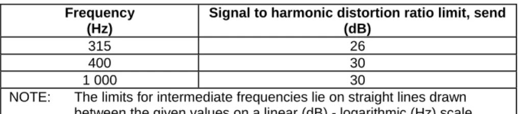
The ratio of signal to harmonic distortion shall be above the following mask. Table 6.5.1.1
Frequency (Hz)
Signal to harmonic distortion ratio limit, send (dB)
315 26 400 30
1 000 30
NOTE: The limits for intermediate frequencies lie on straight lines drawn between the given values on a linear (dB) - logarithmic (Hz) scale.
Measurement method
The terminal will be positioned as described in clause 5.2.
After a correct activation of the system, a sinewave signal at frequencies of 315 Hz, 400 Hz, 500 Hz, 630 Hz, 800 Hz and 1 000 Hz. The duration of the sine wave shall be less than 1 s. The sinusoidal signal level shall be calibrated to -4,7 dBPa at the MRP.
The signal to harmonic distortion ratio is measured selectively up to 3,15 kHz.
An artificial voice according to ITU-Recommendation P.50 [1] or a speech like test signal as described in ITU-T Recommendation P.501 [10] can be used for activation. Level of this activation signal will be -4,7 dBPa at the MRP.
NOTE: Depending on the type of codec the test signal used may need to be adapted.
6.5.2 Receive
distortion
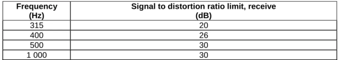
Requirement
The ratio of signal to harmonic distortion shall be above the following mask. Table 6.5.2.1
Frequency (Hz)
Signal to distortion ratio limit, receive (dB) 315 20 400 26 500 30 1 000 30 Measurement method
The terminal will be positioned as described in clause 5.2.
After a correct activation of the system, a digitally simulated sinewave signal at frequencies of 315 Hz, 400 Hz, 500 Hz and 1 000 Hz is applied to the digital interface respectively. The sinewave signal shall be applied to the digital interface at the level of -16 dBm0. The signal to harmonic distortion ratio is measured selectively up to 10 kHz.
An artificial voice according to ITU-Recommendation P.50 [1] or a speech like test signal as described in ITU-T Recommendation P.501 [10] can be used for activation. Level of this activation signal will be -16 dBm0.
6.6
Stability loss and TCLw
6.6.1 Stability
loss
Requirement
With the handset lying on and the transducers facing a hard surface, the attenuation from the digital input to the digital output shall be at least 6 dB at all frequencies in the range of 200 Hz to 4 kHz. In case of headsets the requirement applies for the closest possible position between microphone and headset receiver.
NOTE: Depending on the type of headset it may be necessary to repeat the measurement in different positions. Measurement Method
Before the actual test a training sequence consisting of 10 s artificial voice male and 10 s artificial voice female according to ITU-T Recommendation P.50 [1] is altered. The training sequence level shall be -16 dBm0 in order not to overload the codec.
The test signal is a PN sequence complying with ITU-T Recommendation P.501 [10] with a length of 4 096 points (for the 48 kHz sampling rate) and a crest factor of 6 dB. The duration of the test signal is 250 ms. With an input signal of -3 dBm0, the attenuation from digital input to digital output shall be measured for frequencies from 200 Hz to 4 kHz under the following conditions:
a) the handset or the headset, with the transmission circuit fully active, shall be positioned on one inside surface that is of three perpendicular plane, smooth, hard surfaces forming a corner. Each surface shall extend 0,5 m from the apex of the corner. One surface shall be marked with a diagonal line, extending from the corner formed by the three surfaces, and a reference position 250 mm from the corner, as shown in figure 6.6.1; b1) the handset, with the transmission circuit fully active, shall be positioned on the defined surface as follows:
1) the mouthpiece and earcap shall face towards the surface;
2) the handset shall be placed centrally, the diagonal line with the earcap nearer to the apex of the corner; 3) the extremity of the handset shall coincide with the normal to the reference point, as shown in
figure 6.6.1.
b2) the headset, with the transmission circuit fully active, shall be positioned on the defined surface as follows: 1) the microphone and the receiver shall face towards the surface;
2) For monaural headset the receiver shall be placed centrally at the reference point as shown in figure 6.6.1. For binaural headset, the receivers are placed symmetrically to the diagonal line on both sides of the reference point.
3) the headset microphone is positioned as close as possible to the receiver(s).
Reference point 250
250 Reference
point
NOTE: All dimensions in mm.
Figure 6.6.1
6.6.2
TCLw (or similar parameters)
RequirementThe TCLw shall be ≥ 55 dB.
With the volume control set to maximum TCLw shall be ≥ 46 dB. The volume control shall be set back to nominal after each call unless TCLw ≥ 55 dB can be maintained also with maximum volume setting.
NOTE 1: A TCLw value of 50 dB is a value currently observed and a value of 55 dB is an achievable value with proper design. It has been noted that residual echo may be perceived even with TCLw higher than 50 dB. Measurement Method
The handset or the headset terminal is setup as described in clause 5.2. The handset is mounted in the HATS position (see ITU-T Recommendation P.64 [5]) and the application force shall be 2N on the artificial ear type 3.3 or type 3.4 as specified in ITU-T Recommendation P.57 [3]. The ambient noise level shall be less than -64 dBPa(A) for handset and headset terminals. The attenuation from electrical reference point input to electrical reference point output shall be measured using a speech like test signal.
Before the actual test a training sequence consisting of 10 s male artificial voice followed by 10 s female artificial voice according to ITU-T Recommendation P.50 [1] is applied. The training sequence level shall be -16 dBm0 in order not to overload the codec.
The test signal following immediately the training sequence is a PN sequence complying with ITU-T Recommendation P.501 [10] with a length of 4 096 points (for the 48 kHz sampling rate) and a crest factor of 6 dB. The length of the complete test signal composed of at least four sequences of CSS shall be at least one second (1,0 s). The test signal level is -3 dBm0 (from 50 Hz to 4 kHz). The low crest factor is achieved by random alternation of the phase between -180° and 180°.
The TCLw is calculated according to ITU-T Recommendation G.122 [13], clause B.4 (trapezoidal rule). For the calculation the averaged measured echo level at each frequency band is referred to the averaged test signal level measured in each frequency band. For the measurement a time window has to be applied adapted to the duration of the actual pn-sequence of the test signal (200 ms) choosing the pn-sequence of the third CS-Signal.
NOTE 2: Care should be taken when measuring TCLw: the echo return not to be masked by the residual noise or comfort noise when implemented.
6.7
Double talk performance
During double talk the speech is mainly determined by 2 parameters: impairment caused by echo during double talk and level variation between single and double talk (attenuation range).
In order to guarantee sufficient quality under double talk conditions the Talker Echo Loudness Rating should be high and the attenuation inserted should be as low as possible. Terminals which do not allow double talk in any case should provide a good echo attenuation which is realized by a high attenuation range in this case.
The most important parameters determining the speech quality during double talk are (see ITU-T Recommendations P.340 [8] and P.502 [11]):
• Attenuation range in send direction during double talk AH,S,dt. • Attenuation range in receive direction during double talk AH,R,dt. • Echo attenuation during double talk.
The categorization of a terminal is based on the three categories defined in clauses 6.7.1, 6.7.2 and 6.7.3 and this categorization is given by the "lowest" of the three parameters e.g. if AH,S,dt provides 2a, AH,R,dt 2b and echo loss 1, the categorization of the terminal is 2b.
6.7.1
Attenuation Range in Send Direction during Double Talk A
H,S,dtRequirement
Based on the level variation in send direction during double talk AH,S,dt the behaviour of the terminal can be classified according to table 6.7.1.1.
Table 6.7.1.1 Category (according to ITU-T Recommendation P.340 [8]) 1 2a 2b 2c 3 Full Duplex
Capability Partial Duplex Capability
No Duplex Capability
AH,S,dt [dB]
≤
3≤
6≤
9≤
12 > 12In general table 6.7.1.1 provides a quality classification of terminals regarding double talk performance. However, this does not mean that a terminal which is category 1 based on the double talk performance is of high quality concerning the overall quality as well.
Measurement Method
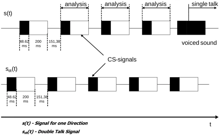
The test signal to determine the attenuation range during double talk is shown in figure 6.7.1.1. A sequence of uncorrelated CS signals is used which is inserted in parallel in send and receive direction.
s(t
)
analysis
analysis
analysis
single
talk
voiced
sound
s
dt(t
)
CS
-
signals
48.62 ms 200 ms 151,38 ms 48.62 ms 200 ms 151,38 mst
sdt(t) - Double Talk Signals(t) - Signal for one Direction
Figure 6.7.1.1: Double Talk Test Sequence with overlapping CS signals in send and receive direction
Figure 6.7.1.1 indicates that the sequences overlap partially. The beginning of the CS sequence (voiced sound, black) is overlapped by the end of the pn-sequence (white) of the opposite direction. During the active signal parts of one signal the analysis can be conducted in send and receive direction. The analysis times are shown in figure 6.7.1.1 as well. The test signals are synchronized in time at the acoustical interface. The delay of the test arrangement should be constant during the measurement.
NOTE: The length of voiced sound of the double talk signal is achieved by repeating one period of the voiced sound for double talk according to ITU-T Recommendation P.501 [10] 10 times and cutting off the initial 3,3 ms of the period of the first voiced sound.
The settings for the test signals are as follows. Table 6.7.1.2 Receive Direction (sdt(t)) Send Direction (s(t))
Pause Length between two Signal
Bursts 151,38 ms 151,38 ms Average Signal Level
(Assuming an Original Pause length of 101,38 ms)
-16 dBm0 -4,7 dBPa Active Signal Parts -14,7 dBm0 -3 dBPa NOTE: When the test laboratories implement different values (within the accuracy range
defined in clause 5.7) it should be indicated in the test report.
The test arrangement is according to clause 5.2.
When determining the attenuation range in send direction the signal measured at the electrical reference point is referred to the test signal inserted.
The level is determined as level vs. time from the time domain. The integration time of the level analysis is 5 ms. The attenuation is determined from the level difference measured at the beginning of the double talk always with the beginning of the CS-signal in send direction until its complete activation (during the pause in the receive channel). The analysis is performed over the complete signal starting with the second CS-signal. The first CS-signal is not used for the analysis.
6.7.2
Attenuation Range in Receive Direction during Double Talk A
H,R,dtRequirement
Based on the level variation in receive direction during double talk AH,R,dt the behaviour of the terminal can be classified according to table 6.7.2.1.
The category of the terminal according to table 6.7.2.1 shall be noted in the test report. Table 6.7.2.1 Category (according to ITU-T Recommendation P.340 [8]) 1 2a 2b 2c 3 Full Duplex
Capability Partial Duplex Capability
No Duplex Capability
AH,R,dt[dB]
≤
3≤
5≤
8≤
10 > 10In general this table provides a quality classification of terminals regarding double talk performance. However, this does not mean that a terminal which is category 1 based on the double talk performance is of high quality concerning the overall quality as well.
Measurement Method
The test signal to determine the attenuation range during double talk is shown in figure 6.7.1.1. A sequence of uncorrelated CS signals is used which is inserted in parallel in send and receive direction. The test signals are synchronized in time at the acoustical interface. The delay of the test arrangement should be constant during the measurement.
The settings for the test signals are as follows.
Table 6.7.2.2
Receive Direction (s(t))
Send Direction (sdt(t))
Pause Length between two Signal
Bursts 151,38 ms 151,8 ms Average Signal Level
(Assuming an Original pause Length of 101,38 ms)
-16 dBm0 -4,7 dBPa Active Signal Parts -14,7 dBm0 -3 dBPa NOTE: When the test laboratories implement different values (within the accuracy range
defined in clause 5.7) it should be indicated in the test report.
The test arrangement is according to clause 5.2.
When determining the attenuation range in receive direction the signal measured at the artificial ear referred to the test signal inserted.
The level is determined as level vs. time from the time domain. The integration time of the level analysis is 5 ms. The attenuation is determined from the level difference measured at the beginning of the double talk always with the beginning of the CS-signal in receive direction until its complete activation (during the pause in the send channel). The analysis is performed over the complete signal starting with the second CS-signal. The first CS-signal is not used for the analysis.
6.7.3
Detection of echo components during double Talk
RequirementEcho Loss (EL) during double talk is the echo suppression provided by the terminal during double talk measured at the electrical reference point.
The category of the terminal according to table 6.7.3.1 shall be noted in the test report.
NOTE 1: The echo attenuation during double talk is based on the parameter Talker Echo Loudness Rating (TELRdt). It is assumed that the terminal at the opposite end of the connection provides nominal Loudness Rating (SLR + RLR = 10 dB).
Under these conditions the requirements given in table 6.7.3.1 are applicable (more information can be found in annex A of the ITU-T Recommendation P.340 [8]).
Table 6.7.3.1 Category (according to ITU-T Recommendation P.340 [8]) 1 2a 2b 2c 3 Full Duplex Capability
Partial Duplex Capability No Duplex Capability Echo Loss [dB] ≥ 27 ≥ 23 ≥ 17 ≥ 11 < 11
Measurement Method
The test arrangement is according to clause 5.2.
The double talk signal consists of a sequence of orthogonal signals which are realized by voice-like modulated sine waves spectrally shaped similar to speech. The measurement signals used are shown in figure 6.7.3.1. A detailed description can be found in ITU-T Recommendation P.501 [10].
The signals are fed simultaneously in send and receive direction. The level in send direction is -4,7 dBPa at the MRP (nominal level), the level in receive direction is -16 dBm0 at the electrical reference point (nominal level).
Shaping filter 1 Shaping filter 2 ∼ ∼ x x CH1 CH2 sFM 1 sFM 2 sAM 1 sAM 2
Figure 6.7.3.1: Measurement signals
∑
π = *cos(2 * ); (t) sFM1,2 AFM1,2 tn F01,2 ; n= 1, 2, etc.∑
π = *cos(2 ); (t) sAM1,2 AAM1,2 tFAM1,2NOTE 2: In the formula, A is determined by the required test signal level as found in the individual test cases. The settings for the signals are as follows.
Table 6.7.3.2: Parameters of the two Test Signals for Double Talk Measurement based on AM-FM modulated sine waves
Receive Direction Send Direction
fm[Hz] fmod(fm) [Hz] Fam[Hz] fm[Hz] fmod(fm)[Hz] Fam[Hz] 250 ±5 3 270 ±5 3 500 ±10 3 540 ±10 3 750 ±15 3 810 ±15 3 1 000 ±20 3 1 080 ±20 3 1 250 ±25 3 1 350 ±25 3 1 500 ±30 3 1 620 ±30 3 1 750 ±35 3 1 890 ±35 3 2 000 ±40 3 2 160 ±35 3 2 250 ±40 3 2 400 ±35 3 2 500 ±40 3 2 900 ±35 3 2 750 ±40 3 3 150 ±35 3 3 000 ±40 3 3 400 ±35 3 3 250 ±40 3 3 650 ±35 3 3 500 ±40 3 3 900 ±35 3 3 750 ±40 3
NOTE: Parameters of the Shaping Filter: Low Pass Filter, 5 dB/oct.
The test signal is measured at the electrical reference point (send direction). The measured signal consists of the double talk signal which was fed in by the artificial mouth and the echo signal. The echo signal is filtered by comb filter using mid-frequencies and bandwidth according to the signal components of the signal in receive direction (see ITU-T Recommendation P.501 [10]). The filter will suppress frequency components of the double talk signal.
In each frequency band which is used in receive direction the echo attenuation can be measured separately. The requirement for category 1 is fulfilled if in any frequency band the echo signal is either below the signal noise or below the required limit. If echo components are detectable, the classification is based on the table 6.7.3.1. The echo
attenuation is to be achieved for each individual frequency band according to the different categories.
6.7.4
Minimum activation level and sensitivity of double talk detection
For further study.6.8 Switching
parameters
Additional requirements may be needed in order to further investigate the effect of NLP implementations on the users perception of speech quality.
6.8.1
Activation in Send Direction
The activation in send direction is mainly determined by the built-up time Tr,S,min and the minimum activation level (LS,min). The minimum activation level is the level required to remove the inserted attenuation in send direction during idle mode. The built-up time is determined for the test signal burst which is applied with the minimum activation level. The activation level described in the following is always referred to the test signal level at the Mouth Reference Point (MRP).
Requirements
The minimum activation level LS,min shall be ≤ -20 dBPa.
The built-up time Tr,S,min (measured with minimum activation level) should be ≤ 15 ms. Measurement Method
The structure of the test signal is shown in figure 6.8.1.1. The test signal consists of CSS components according to ITU-T Recommendation P.501 [10] with increasing level for each CSS burst.
s (t)
t
t
1t
2t
NFigure 6.8.1.1: Test Signal to Determine the Minimum Activation Level and the Built-up Time The settings of the test signal are as follows.
Table 6.8.1.1
CSS Duration/ Pause Duration
Level of the first CS Signal (active Signal Part at the MRP)
Level Difference between two Periods of the Test
Signal
CSS to Determine Switching Characteristic
in Send Direction
~250 ms /
~450 ms -23 dBPa (see note) 1 dB
NOTE: The level of the active signal part corresponds to an average level of -24,7 dBPa at the MRP for the CSS according to ITU-T Recommendation P.501 [10] assuming a pause of about 100 ms.
It is assumed that the pause length of about 450 ms is longer than the hang-over time so that the test object is back to idle mode after each CSS burst.
The test arrangement is described in clause 5.2.
The level of the transmitted signal is measured at the electrical reference point. The measured signal level is referred to the test signal level and displayed vs. time. The levels are calculated from the time domain using an integration time of 5 ms.
The minimum activation level is determined from the CSS burst which indicates the first activation of the test object. The time between the beginning of the CSS burst and the complete activation of the test object is measured.
NOTE: If the measurement using the CS-Signal does not allow to clearly identify the minimum activation level, the measurement may be repeated by using a one syllable word instead of the CS-Signal. The word used should be of similar duration, the average level of the word should be adapted to the CS-signal level of the according CS-burst.
6.8.2
Minimum activation level and sensitivity in Receive direction
For further study.6.8.3
Automatic level control
For further study.6.8.4
Silence Suppression and Comfort Noise Generation
For further study.6.9
Background noise performance
6.9.1
Performance in send direction in the presence of background noise
RequirementThe level of comfort noise, if implemented, shall be within in a range of +2 dB and -5 dB compared to the original (transmitted) background noise. The noise level is calculated with psophometric weighting.
NOTE 1: It is advisable that the comfort noise matches the original signal as good as possible (from a perceptional point of view).
NOTE 2: Input for further specification necessary (e.g. on temporal matching).
The spectral difference between comfort noise and original (transmitted) background noise shall be within the mask given through straight lines between the breaking points on a logarithmic (frequency) - linear (dB sensitivity) scale as given in table 6.9.1.1.
Table 6.9.1.1: Requirements for Spectral Adjustment of Comfort Noise (Mask)
Frequency Upper Limit Lower Limit
200 Hz 12 dB -12 dB 800 Hz 12 dB -12 dB 800 Hz 10 dB -10 dB 2 000 Hz 10 dB -10 dB 2 000 Hz 6 dB -6 dB 4 000 Hz 6 dB -6 dB NOTE: All sensitivity values are expressed in dB on an
arbitrary scale.
Measurement Method
The background noise simulation as described in clause 5.5 is used.
The handset terminal is set-up as described in clause 5.2. The handset is mounted at the HATS position (see ITU-T Recommendation P.64 [5]).