LoKI Progress Update
April 2020
J. Houston, W. Halcrow, R. Heenan & D. Raspino
1. Overview 2
2. Issues for advice 2
3. Engineering 2
3.1 COVID-19 impact 2
3.2 Pre-Build at ISIS 2
3.3 Instruments components 2
3.3.1 NBOA 2
3.3.2 Guide and Vacuum Vessels (in-bunker and bunker-cave) 3
3.3.3 Chopper 1 3
3.3.4 In-Bunker Remote Handling Structures 3
3.3.5 Heavy Shutter 3
3.3.6 Bunker Wall Feedthrough (plug & alignment devices not included in guide order) 3
3.3.7 Chopper 2 3
3.3.8 Collimation Selector Vessel 3
3.3.9 Jaw Sets 3
3.3.10 Sample Snout 4
3.3.11 Sample Stack 4
3.3.12 Detector Vessel 4
3.3.13 Straw Tubes 4
3.3.14 Detector Mechanical Systems including Beamstop Mechanisms 4
3.3.15 Bunker to Cave Shielding 4
3.3.16 Cave Shielding 4
3.3.17 Hutch 4
3.3.18 External Access & Supporting Systems (crane, goods lift, suspended floor) 4
3.3.19 Service Routes & Racks 4
3.4 ESS workpackages 5 4. Detectors 5 4.1 Manufacturing 5 4.2 Electronics 5 4.3 Detector tests 6 4.4 Data processing 7 5. Monitors 7
1.
Overview
Even in the current challenging circumstances, the progress of the LoKI project remains good, with manufacturing beginning for most major components, and more detector testing and data processing currently underway. In this report we outline the progress on engineering matters and address progress on the action items raised by the STAP in September 2019.
2.
Issues for advice
• Continued challenges and progress with processing the data from multiple layers of detector straws
• Changes to the sample area cave, particularly the roof access
3.
Engineering
3.1 COVID-19 impact
• ISIS design team working from home (24 hours lost in ‘change over’, slight re-prioritization of tasks to maximize effectiveness, working at ~85% efficiency due to remote access limitations)
• Pre-build work on-hold due to site closure for COVID-19 (schedule impact not yet clear)
• Manufacture at some facilities has been slowed (schedule impact expected to be manageable, 2-4 weeks lost)
• Manufacture at some facilities is on hold (schedule impact expected to be manageable, 4-6 weeks lost)
• Reflectivity tests for guide awaiting neutronics (schedule impact not yet clear)
3.2 Pre-Build at ISIS
• Instrument equipment has started to arrive on site (previously only prototype parts were on site)
3.3 Instruments components
A more detailed breakdown of the progress of each of the LoKI components has been given below. Briefly, manufacture is underway, or is about to begin, for the NBOA, in-bunker remote handling structures, both choppers, heavy shutter, collimation selector and detector vessels, jaw sets, detector straw tubes, detector mechanical structures; orders have been placed & final designs are underway for sample stack and bunker wall feedthrough; designs are complete for sample snout; designs are almost complete for the cave shielding; and, finally, instrument hutch, bunker to cave shielding and external infrastructure are still to undergo detailed design.
3.3.1 NBOA
• Design completed and sub-TG3 approved
• Manufacture of guide section completed however approx. 60% of copper substrate sections were scrapped as they did not pass the reflectivity test.
• Scrapped parts now re-made and are awaiting availability of neutrons for reflectivity tests.
• All alignment devices manufactured
3.3.2 Guide and Vacuum Vessels (in-bunker and bunker-cave)
• Order placed
• Design underway
• In-bunker sections and bunker wall insert: design complete, TG3 documentation now being compiled for design approval
• Bunker-cave sections in design – completion expected end of May
3.3.3 Chopper 1
• Design completed and sub-TG3 approved
• Manufacture underway
• Parts starting to arrive at ISIS for pre-build
3.3.4 In-Bunker Remote Handling Structures
• Design completed and sub-TG3 approved
• Manufacture underway
3.3.5 Heavy Shutter
• Design completed and sub-TG3 approved
• Manufacture underway
• Parts starting to arrive at ISIS for pre-build
3.3.6 Bunker Wall Feedthrough (plug & alignment devices not included in guide order)
• Design completed, TG3 documentation now being compiled for design approval
3.3.7 Chopper 2
• Design completed and sub-TG3 approved
• Manufacture underway
• Parts starting to arrive at ISIS for pre-build
3.3.8 Collimation Selector Vessel
• Order placed
• Design completed and sub-TG3 approved
• Manufacture underway
3.3.9 Jaw Sets
• Design completed and sub-TG3 approved
• Manufacture underway
3.3.10 Sample Snout
• Design complete, TG3 documentation now being compiled for design approval
3.3.11 Sample Stack
• Order placed
• Design underway
3.3.12 Detector Vessel
• Order placed
• Design completed and sub-TG3 approved
3.3.13 Straw Tubes
• Order placed
• Deliveries starting to arrive on site
3.3.14 Detector Mechanical Systems including Beamstop Mechanisms
• Design completed and sub-TG3 approved
• Manufacture underway
• Parts starting to arrive at ISIS for pre-build
3.3.15 Bunker to Cave Shielding
• 1st pass neutronics completed
• Detailed design not yet started
3.3.16 Cave Shielding
• Detailed neutronics completed – final validation may yet be necessary
• Detailed design well underway
3.3.17 Hutch
• Specification drafted
• In-review at ESS
• Procurement routes under investigation
3.3.18 External Access & Supporting Systems (crane, goods lift, suspended floor)
• Concept layout drafted
• Detailed design not yet started
3.3.19 Service Routes & Racks
• Routes defined
• Concept layout generated
3.4 ESS work packages
A number of key ESS work packages are now progressing well:
• Vacuum system design generated – Availability of kit for FAT & SAT now look like the only real remaining areas for concern
• PSS concept and interface definitions largely complete – Design completion for final TG3 looks at risk. Technical challenges seem to be under control
• Chopper controller design progressing well – no obvious risk to instrument project progress
• Detector software in development (see info from Jude)
• Bunker design and manufacture progressing well – now very few unknowns that effect instrument project progress
A number of key ESS work packages are behind schedule:
• Motion control hardware (control racks & cables, test racks and cables for FAT & SAT)
• Motion safety
• Sample environment
• Mechanical and electrical utilities
• Bunker procedures and concepts of operation (particularly for maintenance and alike)
• General procedures and concepts of operation (particularly for maintenance and alike)
4.
Detectors
4.1 Manufacturing
Most parts of the LoKI detector array carriage are on order and a large fraction has been already delivered to ISIS.
The detectors are on order. PTI in the US is building 32 tubes every 2 to 3 weeks. The first two batches of 32 tubes have been already delivered to ISIS. The third batch is completed at PTI. The fourth is undergoing quality tests at PTI. PTI will ship these batches to ISIS after the Covid-19 lockdown. The same applies for any other batch that they build in the near future. For reference, the detectors already built by PTI will cover more than half of the LoKI rear detector. A large fraction of the mechanics and the B4C detector shielding has already been delivered to
ISIS. This will allow the detector construction to start as soon as we are allowed to safely go back to work at ISIS.
4.2 Electronics
The ADCs are also on order and the first batch of 3 or 4 ADCs will be delivered during the second half of May.
The STFC Technology Department successfully integrated the firmware for the detector signal processing with the FEA firmware to transmit the data to the back-end electronics. The full chain from the detector to the back-end electronics will be tested when we are allowed to safely go back to work at ISIS.
4.3 Detector tests
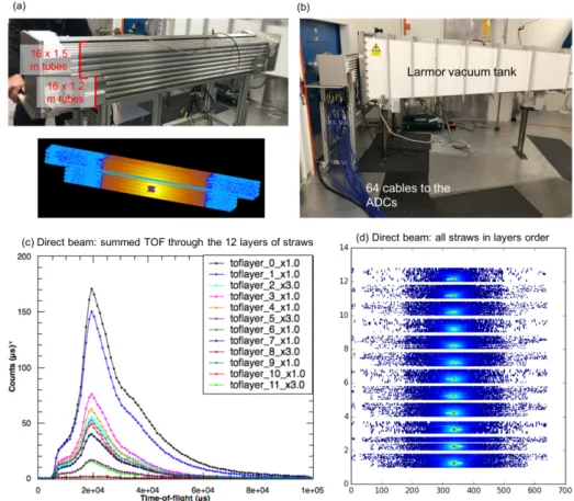
In December 2019, a second LoKI detector prototype was tested on the Larmor beamline at ISIS. In contrast to the previous tests in June 2019, the set-up, shown in Figures 1a and b, included an adapted Larmor vacuum tank to eliminate the effect of parasitic air scatter. The detector prototype consisted of 32 x 1” dia. tubes (in 8 rows by 4 layers deep, each tube containing 7 straws), included 16 x 1.5 m long tubes and 16 x new 1.2 m (the maximum length to be used on LoKI). In these tests, the detectors were successfully operated at the higher voltage of 1100 V. This is the required voltage to achieve the necessary position resolution along the length of the detector straws.
Figure 1. (a,b) LoKi detector set-up on the Larmor beamline (ISIS, UK), and (c,d) direct beam data (no beam stop) displayed in Mantid as a function of layers of straws.
Although the major change in the June to December tests was the high-tension working point rather than the ADC firmware, data was once again collected using the ADC R5560 that will be used on LoKI. The preamps were changed from June, and a minimal change was made to the firmware in the ADC to compensate for the change in the amplitude of the signals from the preamps.
4.4 Data processing
Processing and analysis of the detector data from the most recent detector tests is currently underway. Position corrected data can be converted to Nexus files and displayed in Mantid (Figure 1). Previous tests in June were found to suffer from air scattering between the sample and the detector, which was completely eliminated using the Larmor vacuum tank. This data is being compared with similar measurements the LARMOR detectors, as well as to simulations performed using Geant4. Initial results show that as expected due to “self shielding” of the rear layers by the ones in front of them, the shape of the direct beam relative efficiency vs wavelength changes through the layers of the BCS straws. Work is currently underway to understand how best to be incorporate this into the data reduction procedure in Mantid. Details of efficiency corrections, which will likely have to be detailed down to individual straws, resolution functions, etc., remain to be understood, but the current status and challenges will be discussed with the STAP committee.
5.
Monitors
The prototype of the chopper NitroGEM monitor is complete. It was ready for testing on the ISIS neutron beam when the March cycle was cancelled. At this moment in time the next opportunity to perform this test will be in September. We are using this time to implement some modification on the preamps that we designed for the NitroGEM monitors. In next test with the neutron beam we will assess the possibility to readout the NitroGEM with the same ADC used for the LoKI detectors.
The parts for the halo monitor (monitor directly before the sample position, nothing in beam other than 2 thin Al windows and low pressure N2) are all on order and some of them have
been already delivered. It will be assembled as soon as we are allowed to safely go back to work at ISIS.
6.
Sample environment and sample cave
The detailed designs of the sample cave and sample cave components are almost complete. The snout section within the cave now consists of the fast shutter, vacuum valve, laser alignment mirror, & halo monitor, followed by the extendable snout.
Owing to more relaxed rules at the ESS for the height of instrument cranes, we have raised the height of the roof of the sample cave, and markedly simplified the roof hatch (Figure 2a). The design of the sample table is also underway. Following discussions with the SKADI team and the ESS sample environment group, we have agreed an identical “SANS level” interface above both instruments’ sample stacks (spherical kinematic mounts in Figure 2b, max. 1200 mm below the beam). We are satisfied that previous concerns with sharing sample environments between the two SANS instruments appear to be overcome now.
Finally, the sample environment group at the ESS have agreed to prioritise the design of for LoKI, to be ready before day 1 (Q3 2022):
• Thermostated sample changer for quartz cuvettes;
• Tumbling/rotating cell holder;
Figure 2. (a) Detector cave and sample area. (b) Bird’s eye view of the translation stack with kinematic mounts (top image) and with the sample table mounted on top (bottom image).