Design of a Computer Networking Laboratory for
Efficient Manageability and Effective Teaching
Carlos E. Caicedo, Walter Cerroni
[email protected], [email protected]
Abstract - Computer networking laboratories represent a key resource for ICT-oriented academic organizations. However, due to the particular nature of their users (i.e. students who must learn and experiment while working on real network equipment), it is difficult to design and implement fully functional laboratory facilities while still complying with budget, academic and management objectives. Therefore, physical laboratories are often replaced by virtual or simulated environments, which may limit the student’s learning experience.
This paper describes an innovative approach to the development of computer networking laboratories. The approach defines a specific management infrastructure that allows efficient performance of all the required computer and equipment maintenance tasks, while still supporting a true hands-on experience. Another important feature is the distributed nature of the laboratory infrastructure, where multiple teams of students are allowed to work simultaneously; thus fostering student interaction and teamwork experiences. Index Terms – Curriculum development, experiment-based learning, laboratory design and management.
INTRODUCTION
Computer networks represent one of the major drivers behind recent advancements in the Information and Communication Technology (ICT) field. Therefore, computer networking laboratories are a key resource for those academic organizations that aim to provide their students with the necessary facilities for experimenting as well as learning basic and advanced concepts in networking [1].
In traditional computing laboratories, regular users are not allowed to modify the production network infrastructure or change the workstation network settings, as this might cause severe problems in terms of service availability and distributed resource management.
Typically, users of a computer networking laboratory are students learning and experimenting with the network itself. Therefore, they should be allowed to experiment on real equipment, modify the network topology, and intentionally cause and solve failures and other connectivity problems in order to understand how things work in real-life environments. As a consequence, fully-functional networking laboratory facilities are difficult to design, implement and manage while complying with budget,
academic and management objectives. For these reasons, computer networking experiments are often implemented within virtual or simulated environments, even though this approach may limit the student learning experience.
This is the rationale behind the development of computer networking laboratories incorporating innovative management infrastructures. These infrastructures allow performance of all the required computer and equipment maintenance tasks in an efficient way while still supporting true hands-on (i.e., not simulated) experiences for students as well as providing test bed setups for research activities.
The main contribution of this paper is the description of the innovative design approach adopted by the authors, who have redesigned the computer networking laboratory facilities for the Telecommunications and Networking Program at the School of Information Sciences of the University of Pittsburgh. One of the key aspects of the adopted design is the implementation of an efficient laboratory management framework and a flexible topology building procedure that allows users to fully exploit the physical laboratory infrastructure for a wide range of network configurations. Another important feature is the distributed nature of the laboratory infrastructure, which allows multiple teams of students to work simultaneously in order to foster interaction and provide experience in working as a team.
A laboratory-based course on computer networks fundamentals has also been designed to make use of the facility, exploit its strengths and test the level of compliance to its design objectives. Students in the laboratory course possess the typical computer networking expertise of senior undergraduates or graduate students of the ICT fields, such as CS, IS, Telecom and EE. The course has been developed to promote self-directed learning and problem solving within a team-oriented environment.
After a brief discussion about the possible approaches to the design of a computer network laboratory, the remainder of this paper is dedicated to the objectives and the implementation details of the laboratory infrastructure at the University of Pittsburgh. It concludes with a description of the laboratory-based course that was developed.
APPROACHES TO NETWORK LABORATORY DESIGN
A computer network laboratory infrastructure consists of several components:
• active network devices, such as switches, hubs, routers, wireless access points, firewalls;
• passive network devices, such as cabling, patch panels, equipment racks;
• terminal nodes, i.e. personal computers, laptops, PDAs. In addition, all of these devices require an appropriate management infrastructure (a management plane) in order to configure them appropriately and to allow interactions that comply with the objectives of a specific laboratory experiment.
Network laboratories can be implemented via several approaches, such as simulated environments, virtualized and physical infrastructures.
Simulation environments are typically used when the experiments to be performed are too expensive or too difficult to be undertaken with real equipment. In this case, dedicated software is used to simulate the most relevant behaviors of the network elements and their interactions. Among the most popular network simulation tools are ns2 [2] and OPNET [3].
Virtualized infrastructures are based on the concept of virtual machines (VMs), which are used to create multiple instances of servers, clients and routing systems within the same physical machine. Virtualization software, such as VMware [4] or Xen [5], is employed to make a limited set of systems represent a larger set of network equipment and hosts [6]. It also enables the administrator to easily restore each system configuration to a default state by reloading a VM when required [7].
Physical infrastructures make use of real devices for the setup of a network laboratory deployed in either a centralized or distributed topology. In a centralized setup, only one set of active network devices is present in the laboratory. This approach allows for the centralized allocation and management of networking devices at a relative low cost. However, it restricts laboratory experiences to one group of students at a time. In contrast, with a distributed setup, several network device workbenches (each possibly contained within one cabinet rack) are deployed within the laboratory. Each workbench houses enough devices for a team of students to accomplish most of their basic learning needs. This setup allows for several teams of students to be working in the laboratory at the same time and for devices from different workbenches to be interconnected to realize more complex topologies. However, this approach is more expensive to implement and can become difficult to manage, if not planned correctly.
OBJECTIVES OF THE NETWORKING LABORATORY
In 2007, the Industry Advisory Council of the School of Information Sciences’ Telecommunications Program recommended that the laboratory infrastructure used to teach computer networking concepts needed to be completely redesigned. This became an opportunity to implement a new laboratory infrastructure based on the following objectives (listed in no particular order):
[O_1] Support for hands-on laboratory experiences for students
[O_2] Capability of supporting multiple teams of students working at the same time
[O_3] Enabling of inter-team interactions [O_4] Teaching of modern networking concepts [O_5] Support for research activities
[O_6] Facilitation of management and configuration The analysis of these objectives led to the definition of the desired implementation characteristics for the new laboratory infrastructure, which are listed below:
[C_1] Distributed design [C_2] State of the art equipment
[C_3] Flexible management infrastructure [C_4] Support for objective-based experiments
Adequate mapping of objectives to implementation characteristics made it easy to justify many of the design and equipment purchasing decisions. It is worth mentioning that budget and time constraints also played a part in the decision making process. The mapping is shown in Table I.
TABLE I
MAPPING OF DESIGN OBJECTIVES TO IMPLEMENTATION CHARACTERISTICS
C_1 C_2 C_3 C_4 O_1 X X X O_2 X X O_3 X X O_4 X X O_5 X X O_6 X
Through careful planning and with well selected implementation guidelines, it was possible to fully comply with the objectives set for the laboratory, while satisfying the budget constraints. Setup of the infrastructure was completed within a three-month time span.
DESCRIPTION OF THE LABORATORY
The devices in the networking laboratory are distributed among several workbenches and a core equipment rack. This is in contrast to the centralized equipment rack approach that was in place at the facility before mid-2008.
I. Equipment and Layout
As depicted in Figure 1, the laboratory consists of four group workbenches, one core equipment rack and a research workbench. Each workbench will conveniently allow groups, with two to four students each, to be working independently of experiments being conducted at other workbenches. This permits up to four separate student groups to be in the laboratory at any given time. The devices installed in each group workbench are listed in Table II.
FIGURE 1
GENERAL LABORATORY STRUCTURE TABLE II
GROUP WORKBENCH
Device Quantity Comments / Description Desktop PC 3 All PCs have two Gigabit capable
Ethernet interfaces. They are configured as dual-boot systems: Windows Vista Ultimate and Linux Laptop computer 1 For use in experiments involving
mobile environments. Supports IEEE 802.11a/g/n and Bluetooth
Multi-protocol router
2 Configured with an advanced IP services image (support for security, MPLS and IPv6). Each router has 3 Ethernet interfaces
Gigabit Switch 1 Gigabit capable switch with 24 ports Fast Ethernet Hub 1 Hub with 24 Fast Ethernet ports Wireless Access
Point
1 Wireless access point with support for IEEE 802.11a/g/n and DD-WRT (Linux based firmware)
Patch panel and equipment rack enclosure
1 Feed-through patch panel with 48 ports
The devices in the core equipment rack provide more advanced capabilities and greater connectivity than those present in the group workbenches. These devices allow for the management and, if required, for the interconnection of all the routers in the laboratory. The connectivity structure of the laboratory (described later) designates the core rack as the point from which actions that can affect the whole laboratory can be launched.. It can also be used as an intermediary point to interconnect one group workbench to another when required. The devices installed in the core equipment rack are listed in Table III.
The research workbench and its associated equipment rack house the PCs and networking devices for research activities. As such, the devices in this workbench will change depending upon the requirements of the research being conducted.
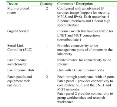
TABLE III CORE EQUIPMENT RACK
Device Quantity Comments / Description Multi-protocol
router
2 Configured with an advanced IP services image (support for security, MPLS and IPv6). Each router has 4 Ethernet interfaces and 1 Serial high speed interface
Gigabit Switch 1 Ethernet switch that handles traffic for LNET and MGT connections (described later)
Serial Link Controller (SLC)
1 Provides connectivity to the management ports of all routers in the laboratory
Fast Ethernet switch/router
1 Switch/router for connectivity to the Internet
Fast Ethernet Hub 1 Hub with 24 Fast Ethernet ports Patch panels and
equipment rack enclosure
2 Feed-through patch panel with 48 ports. Patch panel 1 provides connectivity to core routers, SLC and the LNET and MGT networks.
Patch panel 2 provides connectivity to group workbenches and research workbench
II. Cabling and Connectivity Management
The cabling infrastructure for the laboratory was deployed using CAT6 cables to support Gigabit speeds. Optical links have not been deployed, but the routers and switches in the laboratory are capable of supporting optical interfaces in the future.
To facilitate connectivity management and cable installation, all patch panels are feed-through patch panels. These panels do not require punching down the cable to enable a data port. The ports of all networking devices are available to laboratory users via dedicated ports in the patch panels. In this way, nobody has problems reaching a particular device port. Additionally, each team of students that uses a specific workbench is assigned a color for their cables. The team will only use cables of their color throughout the laboratory; this makes it easier to track each of the team’s connections and facilitates hosting many teams in the laboratory simultaneously. A fifth color denotes cables used for management connections, set by the laboratory administrators/instructors, which must not be tampered with by students.
In order to support manageability to all devices in the laboratory and to allow for a wide range of connectivity topologies, several special data ports and connections were installed in the group workbench patch panels:
The Laboratory Network (LNET) connections – All of the ports labeled LNET in each of the workbenches are connected to a common switch on the core rack. This provides the means to have a connectivity setup that interconnects all workbenches. If the LNET port on each workbench is connected to a workbench hub/switch, then all the PCs connected to the hub/switch will be connected to all other PCs also connected to the LNET network.
The Management Network (MGT) connections – All of the workbench ports labeled MGT are connected to a common switch on the core rack which is also connected to a Serial Link Concentrator (SLC) device and a management workstation. This network provides connections for laboratory device management functions.
The Workbench to Core (WK) connections – There are six WK ports on each workbench. They can be used to connect any device on the workbench to the core rack. This provides access to devices in the core rack and a means to interconnect devices in different workbenches when necessary.
III.Network device management
The various networking devices in the laboratory (routers, switches and hubs) are used in experiments which may require the configuration of operational parameters in each device via their serial management interfaces. To provide flexible access to these interfaces, we use a Serial Link Concentrator (SLC). The SLC is a commercial device that houses many serial interfaces to which all the serial (RS-232) management ports of the network devices are connected. In this way, any user of the laboratory can connect to the SLC (via a MGT port) and from there manage any device in the laboratory (if he/she has the right access permissions). Thus, the SLC provides a centralized point for configuring the devices in the laboratory without requiring the movement of cables to connect to a device’s management port or fixing a data port (and allocating an IP address) on each device in order to provide configuration management capabilities.
The SLC can also be reached via a secure data port connected to the Internet. This capability will be used in the future to provide distance learning experiences in the laboratory.
IV.PC Management
In order to provide the laboratory with multiple operating system platform capabilities, all desktop PCs and laptops have been configured for now as dual-boot systems. However, the Linux operating system is used the most to perform experiments specific to computer networking topics, since it provides a complete suite of advanced and flexible open-source software tools appropriate to this purpose.
Each PC is equipped with two Gigabit Ethernet interfaces, whereas each laptop has a Gigabit Ethernet and an IEEE 802.11 a/g/n wireless card. This multi-homed host configuration allows the laboratory user to configure PCs for multiple purposes. For example, a PC may act as a host connected to a given LAN through one interface while through the second interface it can capture traffic on a different network segment or connect to the management network (MGT). Furthermore, a Linux PC with multiple network interface cards can also be configured to execute forwarding functions and routing protocols as well as to implement network address translation (NAT) and packet filtering operations.
Such a multi-purpose use of a Linux PC makes it a very powerful tool for learning and experimenting in networking laboratories. However, it also requires that the laboratory user (i.e. the student) be allowed to modify the interface IP parameters and the configuration of the system’s networking functions, which are actions that require administrative privileges. On the other hand, it is clearly not advisable to give students full administrative access to the PCs. To solve this issue, the “sudo” command prefix was adopted, which allows the system administrator to delegate specific privileged commands to a given user or group of users. The user is then allowed to execute these commands with administrative privileges [8].
With this approach, students may reconfigure specific parameters of a Linux PC at runtime only. They are not authorized to establish permanent settings or to modify non-network related configurations. Therefore, when a PC is restarted, its default network settings are restored facilitating PC administration.
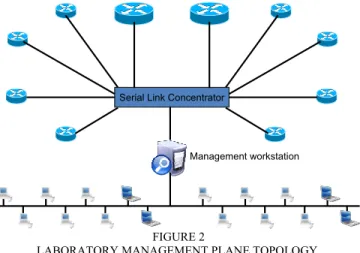
V. Management plane topology
Figure 2 provides a view of the network topology used in the laboratory to provide the management functions described in the previous sections.
Serial Link Concentrator
Management workstation
FIGURE 2
LABORATORY MANAGEMENT PLANE TOPOLOGY.
In addition to the SLC, another key component in the management topology is the management workstation. From this station, the laboratory administrator or instructor can manage any active device and any PC in the laboratory. A series of custom-built scripts and programs allow the administrator, to send software updates and patches to all PCs when required and to reboot any system. In general, this topology and its components provide for a management plane that simplifies the management tasks of the laboratory.
LABORATORY-BASED COURSE
A laboratory-based course has been developed in order to evaluate whether or not the facility meets its design and learning objectives. This course provides students with experience on computer networking topics through hands-on experiments using modern equipment and services while
also promoting team-work. During the course, students progress via a bottom-up methodology through increasingly-complex networking concepts, from basic connections between PCs, to routing, to advanced network applications. Each laboratory experience is not a stand-alone experience; rather, it is structured to build on concepts and knowledge gained by the students in previous exercises. The course covers topics such as connectivity at the physical layer; Ethernet LAN performance and virtual LAN (VLAN) configuration; wireless LAN planning and deployment; IP address planning and management; IP routing protocols configuration including RIP, OSPF and BGP; virtual private networks (VPN) and traffic engineering implementation through Multi-Protocol Label Switching (MPLS); TCP performance evaluation; NAT and packet filtering techniques; network monitoring and management; signaling protocols for voice over IP (VoIP) services and web-based services configuration.
In order to promote critical thinking and foster problem solving skills, the exercises do not force the students to follow a recipe-like, step-by-step approach. There are no lectures in the course and the students apply the knowledge gained from previous theoretical courses on computer networks, integrated with some specific suggested readings. Furthermore, the requirements for each exercise are presented as a statement of goals to be accomplished. This mimics the real world environment that students will deal with in their profession where they have to devise their own work plan, search for relevant documentation, use their expertise to solve problems, verify the correctness of the proposed solution to meet the goals and prepare appropriate technical reports while respecting deadlines. Additionally, the course requires students to identify and complete a final project which emphasizes self-driven research and problem solving.
In the course, the instructor acts only as a supervisor and a consultant. As a supervisor, he/she demands and expects the completion of the objectives of each assignment within a mandated time schedule. As a consultant, the instructor provides guidance towards finding the solution to practical problems that a student might encounter during a laboratory experiment.
The inter-team interactions promoted by many of the experiments have been particularly successful. Our student population is very diverse and the lab experiences promote the interaction of student teams comprised of people from different countries, backgrounds and knowledge levels. In this environment, students have to adopt communication styles appropriate for the interactions of future information professionals in a globalized world.
EXAMPLES OF LABORATORY EXPERIMENTS
A few examples of the experiments performed by students in the laboratory-based course are described in this section. The examples selected are the MPLS basics and VLAN management experiments, respectively.
The purpose of the MPLS experiments is to understand the advantages that this state-of-the-art technology offers to today’s network operators [9]. The goal of the experiments is to set up an MPLS scenario using multiple IP routers, according to the topology shown in Figure 3. The group workbench routers act as two Customer Edge (CE) nodes and the core routers as two Provider Edge (PE) nodes. The starting topology includes the links represented by solid lines only, whereas the direct link connecting the two CEs (dashed line) it is added at a later stage.
CORE ROUTERS WORKBENCH ROUTERS MPLS CE CE PE PE LAN 1 LAN 2 LAN 3 (VPLS) FIGURE 3
TOPOLOGY FOR MPLS EXPERIMENTS
The first experiment consists of configuring the MPLS Label Distribution Protocol (LDP) on each router so that packets exchanged between LAN 1 and LAN 2 are actually label-switched through the two PEs according to the underlying OSPF routing process.
The second step is to configure a layer-2 VPN between hosts connected to LAN 3 using Ethernet over MPLS. A new Label Switched Path (LSP) between the two CEs is established and Ethernet frames exchanged within LAN 3 are transported as single MPLS packets along the LSP. The result is that the two segments of LAN 3, although distributed over two remote sites, appear as if they were connected through a direct link, i.e. a pseudo-wire implemented using MPLS to build a networking solution commonly known to operators as Virtual Private LAN Service (VPLS).
The third experiment on MPLS requires a modification of the topology, with the direct link between the CEs now being active and representing the new shortest path for packets exchanged between LANs 1 and 2. The goal here is to learn about traffic engineering by forcing packets which originate from LAN 1 and are directed to LAN 2 to follow the alternative path across the PEs (represented by the blue arrow in Figure 3), even though it is not the shortest path and would never have been chosen by classic OSPF routing. Packets in the opposite direction keep following the shortest path (represented by the red arrow). The experiment is successful when a suitable one-way LSP is established between the CEs using the MPLS traffic engineering tunnel capabilities offered by the routers.
Another experiment, shown in Figure 4, requires the students to configure the group workbench Ethernet switch and to define different VLANs. In particular, one of the goals is to learn how to set up a VLAN trunk that allows two VLANs to span across multiple switches. To perform this experiment, each group of students needs to extend their network topology beyond their own workbench and work in cooperation with another group, as illustrated in Figure 4. Each switch is configured with VLANs 2 and 3 and the switches are interconnected through a trunk port. The VLAN trunk is effectively implemented applying the IEEE 802.1Q tagging protocol [10].
VLAN3 VLAN2
WORKBENCH A SWITCH
IEEE 802.1Q trunk WORKBENCH B
SWITCH
FIGURE 4
EXAMPLE TOPOLOGY FOR VLAN EXPERIMENTS
In each of the previous experiments, as well as in others not mentioned here, the students must use their skills to complete the assignment and verify the correctness of the implemented solution by reporting all the configuration commands executed as well as commenting on the results obtained from relevant traffic captures using a protocol analyzer.
The examples illustrated above have been chosen to demonstrate how the particular nature of the laboratory infrastructure design presented here allows for the implementation of flexible experiments that improve the effectiveness of teaching computer networking topics. In particular, the MPLS laboratory is a very nice example of how the design easily enables real hands-on experience in one of the most up-to-date topics of interest for telecommunications industry and operators. In addition, the VLAN trunk example is very useful to understand how cooperation and teamwork can be fostered thanks to the distributed setup of the laboratory infrastructure.
CONCLUSIONS
The design, management methods and approaches that the authors used to develop a laboratory infrastructure as well as one of its associated courses have provided an effective environment for the teaching and learning of computer
networking concepts through hands-on experiments. Students have reported, through surveys, a great deal of satisfaction with the usefulness of the laboratory exercises and its environment (> 90% approval). Lab exercises that emphasize routing concepts were particularly popular. The students have suggested incorporating more advanced experiments in a separate course and more flexibility in having access to the lab outside class hours. This reflects their desire to continue learning and willingness to use the laboratory and its capabilities.
More than just being a mere collection of devices in a laboratory space, this laboratory provides an environment that facilitates multi-team interactions, cooperative approaches to problem solving and engages the students in self-directed learning. The coherent integration of academic and management objectives have made this laboratory a successful facility for teaching and research activities. A modest budget was spent to build it. The authors hope that the methodology and experience documented here can help other instructors and institutions to develop effective and manageable laboratory facilities.
REFERENCES
[1] Comer, D. E., “Hands-on Networking with Internet Technologies”, 2nd edition, Prentice Hall, 2005.
[2] “The Network Simulator – ns-2”, http://www.isi.edu/nsnam/ns/ [3] “OPNET Technologies, Inc.”, http://www.opnet.com/ [4] “VMware”, http://www.vmware.com/
[5] “Xen”, http://www.xen.org/
[6] Galan, F., Fernandez, D., Ruiz, J., Walid, O., de Miguel, T., “Use of virtualization tools in computer network laboratories”, Proceedings of ITHET 2004, June 2004.
[7] Ramalingam, D., “Practicing computer hardware configuration and network installation in a virtual laboratory environment: A case study”, Proceedings of FIE 2007, October 2007.
[8] “Sudo main page”, http://www.gratisoft.us/sudo/sudo.html [9] Rosen, E., Viswanathan, A., Callon, R., “Multiprotocol Label
Switching Architecture”, IETF RFC 3031, January 2001.
[10] IEEE 802.1 Working Group, “Virtual Bridged Local Area Networks”, IEEE Standard 802.1Q-2005, May 2006.
AUTHOR INFORMATION
Carlos E. Caicedo, Ph.D. Candidate. Telecommunications Program of the School of Information Science, University of Pittsburgh, Pittsburgh, PA, [email protected]
Walter Cerroni, Assistant Professor. Department of Electronics, Computer Science and Systems (DEIS). University of Bologna, Bologna, Italy.