(DOI: dx.doi.org/14.9831/1444-8939.2014/2-4/MAGNT.28)
A Case Study on Variability Management in Software Product Line
Sabir Hussain(1), Muhammad Asif(2), Muhammad Shahid(3)1) Department Of Computer Science, National Textile University Faisalabad Pakistan 2) Assistant Professor, Department of Computer Science, National Textile University Faisalabad
Pakistan
3) Lecturer, Department of Computer Science, National Textile University Faisalabad Pakistan Abstract
A product line is a collection of products that together address a specific business sector section or satisfy a specific mission. While software product line satisfies a market or segment by using its common set of features that are developed as a core assets for different products of a family. SPLE (Software product line engineering) is composed of two major parts one is Domain Engineering and other one is Application engineering. One common and major issue that is to be faced in SPL is to manage variability at different phases of SPL. Despite of this there are many other models like FODA, PuLse, Cobra etc. that are purposed to manage VM in SPL but have many back draws and implications during different phases of implementation. In this paper we will explore first some well-defined processes and methods to manage VM in better way as compared to existing models as described in Cobra, PuLse, FOAD etc. and then apply a case study of LMS(Logistic Management System) to identify variability in SPL. We have also discovered that how the defined processes and models manage variability at different phases of SPL and also highlight advantages and disadvantages of this model.
Keywords: Variability Management, Software Product Line, Logistic Management System Introduction
In recent years SPLE(Software product line engineering) has dramatically gained substantial attention because it has been argued that SPLE delivers a promising technique to improve the development of a huge variety of improved, better, cheaper and faster [1] software concentrated systems. By using SPLE it has been stated that in some case’s the quantity increased with low cost, enhanced time to market and also quality improved much better as compared to existing old traditional reusing techniques to develop a product[2]. The development of the software products by using SPL (Software Product Line) can be developed easily and rapidly by taking the advantage of reusing core assets like frameworks, patterns, designs, components and documentation. There are a variety of products that are supported by SPLE diverges
individually to support entirely dissimilar market segments or specific customers. As a result here comes the concept of variability, which is an important theory in SPLE. Variability has the capability for an artifact to be personalized, organized, changed or extended for the use of particular or in an unambiguous context[3]. Various artifacts that are used in variability to develop different products in SPL must be exploited, signified, defined, executed and developed during the whole lifecycle of that SPL[4]. This is the nutshell when practitioners and researchers refer to variability management (VM) in SPLE and it is also when we use the term variability in this research.
Domain Engineering and application engineering are two main parts of the SPLE.
(DOI: dx.doi.org/14.9831/1444-8939.2014/2-4/MAGNT.28) The core asset of the product line that is called
product-line architecture belongs to domain engineering. The main objective of product line engineering is to build products by understanding and monitoring the commonality between a set of similar software system or controlling common functionality that exists between a product family that is shared between products, system can be customized or changed to specific needs by using the concept of variability. Therefore a key point between the product families is to understand and manage the concept of variability that is significant for the success of software product line. Software growth can be determined by managing variability in SPL. There are some issues that are discussed in different research papers such as:
Development of Variability[5]
Managing unvarying variability over the all phases of SPLs[6]
Documentation and modeling of variability[7, 8]
Mapping of family assets with variability[9]
The SPLs contains multiple-View Meta-Modeling[10]
The identification of variability and commonality [11]
To manage VM tasks is an extremely complex and challenging, therefore it is essential that different techniques, approaches and tools should support VM[7, 11]. There are some outstanding methods and techniques that have been presented or described in different research papers to manage variability in SPL like FODA, PuLse, Cobra, and many more with some back draws. While FODA (feature oriented domain analysis) method is the first input to manage variability in 1990[9]. However many problems still need to be resolved [12]. There is no generally well known technique or notation that is used to accomplish variability of all stages of SPL because variability ascends in each stage of SPL and needs to establish traceability of identifying product variability from the initial stage to product design, implementation and testing. Therefore in this paper [13] it has been claimed that variability is managed uniformly throughout life cycle of SPL, at each phase specifically artifacts, process are purposed. Furthermore a detailed case study is implemented on purposed methodology to verify and check how these methods help to manage variability uniformly at every stage of SPL.
Background
There are several techniques and methods that are introduced to manage variability in SPL. Each model has purposed some different methodology to cater the problem of VM like PuLSE (Product Line Software Engineering), KobrA, FAST (Family-Oriented Abstraction, Specification, and Translation), FORM (Feature-oriented reuse method), and PoLITe. One model named with PuLSE[14] is purposed to overcome the problems that occurred in most of the other research in SPL which lacks of customizability, and lost their
focus, which only covers domains as opposed to products. PuLSE methodology enables the notation and deployment of SPL for a large number of products with enterprise background. This methodology was achieved by having focus on products in all the phases of PuLSE and also giving customizability of its different phases and components also includes incremental introduction capability, a well-structured deployment and a few main product development situations. In a particularly domain applications can be designed more significantly by reusing their
(DOI: dx.doi.org/14.9831/1444-8939.2014/2-4/MAGNT.28) similarities. By developing core assets for
reusability for a domain allows multi applications to build efficiently from existing core assets. According to PuLSE methodology domain engineering methods are not as efficient as expected this is due to following three reasons:
Wrong and misguided application scope
Laps of operation guidance
More focus on organizational issues KobrA[15] is component based product line approach and emphasizes on significantly increase of reusability in industrial maintenance and software development. Rather than going into old techniques organizations follow a product line approach after gathering the parts of “Old” systems in a temporary manner, which gives good results by increasing efficiency, high quality consolidation of software assets, software core is reused and also focuses on the resources which can accommodate changes from customer by using this core.
There is a wrong perception about the usage of product-line development that is unsuited with “usual” development of single system a lot of developers has thought that product line development approach not comfortable for them to develop “single system” according to some developers its forcefully adaption technique. The component based software engineering differs from object oriented paradigm because it gives interoperation of binary code modules. Organization creates component based systems and expected that many similarities will be shared and particularly uses the same components. There
are some critical components which handles the variability’s in a family of systems.
FAST[16] process applies product-line principles to software engineering process. However a family of products can be defined from a common platform. This platform is composed from similarities between several products close to each other. In this paper it is also described that how same family has common basis and variability for products[17]. It also describes about core assets development and acquisition for product-line[18]. The variability’s within the product family members can be managed and implemented by using various variation techniques like conditional compilation. A detailed elaboration about variability in product-line architectures can be found in [18] as an example. The core objective of FAST is to decrease production costs by reducing duplicate, multiple works and with quick delivery in market. FAST process can be implemented by a consistent, smooth and disciplined way. It is called PASTA model where PASTA is (Process and artifact state transition abstraction). FAST process can be followed by using PASTA model. PASTA process provides a way during the execution of FAST process and also determines a set of steps that how get success during the current step. The role of PASTA in software engineering process is to provide an iteration and reusability of future processes.
Below is a centralized model that summarizes the information mined from the core assets particularly the dependency information. On basis of this model product line organization can anticipate what is needed or involved to build a specific product.
(DOI: dx.doi.org/14.9831/1444-8939.2014/2-4/MAGNT.28) Figure 1 Contributors to the Core Asset Base[19]
Literature Review
This section describes methodology of [13] with its defined processes and methods. Common characteristic and variation (C&V) must be achieved and managed at each stage of SPL or phases of abstraction[20]. As described in the below diagram each stage of product development is labeled with the way
to figure architecture with respect to product line in SPLE and also at each level of C&V artifacts are defined with each process. First the overall description of how to SPL can be used to build software development is displayed in below pictorial diagram Figure 2.
(DOI: dx.doi.org/14.9831/1444-8939.2014/2-4/MAGNT.28) Figure 2 Suggested process and artifacts for VM [13] As it is depicted in Figure 2 the purposed methodology is made out of two primary parts domain engineering (DE) and second is application engineering (AE). We will
concentrate of domain engineering (DE) rather than going into the detail of application engineering (AE). So let’s start from step 1.
Step 1: Scoping
In this step particular prerequisites of every product are recognized which should be part of product line (PL). Scoping is introduced to conclude the boundaries of SPL. The boundaries of conceptual groups are also recognized. Artifacts that are involved in this stage are feature list, refined feature diagram and enhanced product map. The term features [21] in SPL define a projecting and unique concept or a characteristic that varies
according to various specific requirements needed by various stockholders [22]. Furthermore there are different types of feature like External features [23], mandatory features, optional feature and variant features [23]. The stakeholders such as product experts, maintainers, users, and developers identify characteristics of the product by analyzing it and also help to collect product related materials and this all procedure helps to make
(DOI: dx.doi.org/14.9831/1444-8939.2014/2-4/MAGNT.28) feature list. The enhanced product map helps
to identify individual products feature and which features are required to compose each
product. Features are grouped by property and listed with the help of (EPM) enhanced
product map.
Figure 3 Features and Product are displayed using enhanced product map (EPM) [13] A feature can be variable or common among
the different products. In “Product A” all features are involved of the product line while a feature can be implemented in set of the product-lines or in a single member [24]. Gray shaded lines are representing variability among the product families. There exists a value relationship between product families in (EPM) enhanced product map as shown in figure 3.
Depended or Involved in N—a feature is depended if some other feature N is involved and so on.
Excluded from N or Omitted from N— a feature will be omitted or excluded if a feature is N is nominated.
Step2: C & V Modeling
In this step, a way is provided how to identify the variation in product family and by analyzing commonality and variability it is identified that what is common across the domain of SPL. Here are the artifacts that are purposed: i-A refined use-case model (RUM) ii-A business service scenario (BSS) iii-A BSCV (business service commonality and variability) decision model
Functional requirements of system can be determined by utilizing use case model. A UCM (Use case model) delivers a technique for describing and understanding the FR (functional requirement). It is also used to determine C &V (variation and commonality) by using stereotype<<optional>> and <<mandatory>>. The terminology of stereotype is naturally used to model
(DOI: dx.doi.org/14.9831/1444-8939.2014/2-4/MAGNT.28)
variability because it is the usual way to be presented by UML
Figure 4 Refined use-case model [13]
In fig 4 stereotype <<uses>> means that feature 5 is also included the behavior of feature 4. A (BSS) business service scenario and (UCS) use case scenario could be utilized
to determine the comprehensive functional and non-functional attributes. Below figure 5 is representing business service scenario and fig 6 is representing proposed in [9] paper.
Figure 5 Business service scenario [13] In the product line BSCV decision model defines the variable and optional necessities of products. To determine variability and
commonality of the business service BSCV decision model is used as described in below figure 6.
(DOI: dx.doi.org/14.9831/1444-8939.2014/2-4/MAGNT.28) Figure 6 A decision model BSCV for business service (BSS)
Figure 7 Use-case model represented by BSCV decision model Step 3: Architecture modelling
Building design or architecture is an important component toward the achievement of any product venture, not simply SPLE. A SPLA portrays the shared characteristics among the dissimilar products and likewise unmistakably depicts the variability which is permitted among the products. As being what is indicated a SPLA is foremost to typically attain the characteristics of the different items in a SPL [25]. SPLA purpose three core artifacts that are:
i-Architecture View ii-Quality Goal Specification (QGS) iii- Decision Model for the Architecture of Commonality and Variability (ACV).
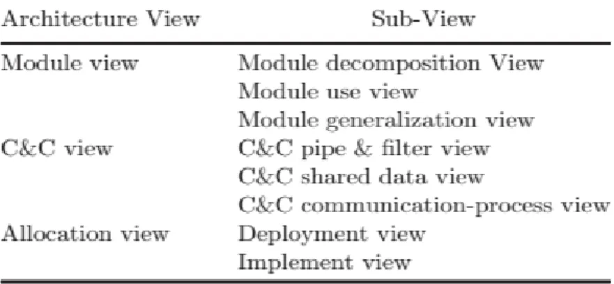
Keeping in mind the end goal to delineate the shared characteristic and variability of the product offering construction modeling, a few view types as architectural features are utilized, including view type, allocation view and others as shown in figure 9. Each one view type comprises of a few sub views, as is shown in Fig1.
Several views are used to present the variability and commonality of SPLA including module view type, allocation view type and component and connector(C &C) view type. Now each architecture view is sub divided into more sub views, as described in below figure.
(DOI: dx.doi.org/14.9831/1444-8939.2014/2-4/MAGNT.28) Figure 8 Architecture view type [13] A Case Study
In the following segment, a real time case study is implemented that shows the provision of the suggested model, artifacts and processes into particular areas keeping in mind the end goal to delineate the inspirations for our research. The model of [13] is implemented to the (LMS), a web-based solution for logistic management. For the case study, it is supposed that LMS is supporting a family of products that are composed of East Course Trucking Company, Total A&G Trucking Company and
Al-Nahif Trucking Company. In phase 1, features are mined, examined, and grouped, as indicated in table-1.
In this table features with gray background are representing variability among the family of products with respect to features. For examples “Total A&G Trucking Company” is composed of twelve features. Relationship column is used to identify the dependency of features on each other.
Table 1 Enhanced product map for LMS
East Course Trucking Company Total A&G Trucking Company Al-Nahif Trucking Company Relationship LMS Order Management
1 Add order record Involved in 2
2 Order record inquiry 3 Driver payroll 4 Chassis split 5 Auto charges 6 Auto payments 7 Add document record Involved in 8 8 Document record inquiry LMS Financial Management 9 Manifest Billing 10 Invoicing Build
11 Payments record Involved in 13
Feature
(DOI: dx.doi.org/14.9831/1444-8939.2014/2-4/MAGNT.28) 12 Payment record
Inquiry
13 Invoice Posting Involved in 14
14 Invoice Posting Inquiry 15 Weekly Payment LMS Fleet Management 16 Vehicle Management 17 Insurance 18 Maintenance 19 Tracking
20 Fleet Security &
Controller Involved in 21 21 Remote Disabling Vehicle System 22 Fleet Scheduling 23 Fleet Allocation
Refined features diagram is used to present the dependency between the features and also feature group variation. In order to identify the FR
(functional requirement) of LMS, a refined use-case model is used on the basis of refined feature diagram of LMS. In figure 10 a business service has been described which has 3 actors and 6 use cases for “Fleet management System”. Included Product LMS Order Management LMS Fleet Management LMS Financial Management Add Order Record Driver Payroll Auto Charges Auto Payments Vehicle Management Insurance Maintenance Tracking Manifest Building Invoice Build Payments Record Payment Record Inquiry
(DOI: dx.doi.org/14.9831/1444-8939.2014/2-4/MAGNT.28) Can be Excluded Optional Add Document Order Record Inquiry Chassis Split Document Inquiry Invoice Posting Invoice Posting Inquiry Weekly Payment Fleet Security & Controller RDVS Fleet Scheduling Fleet Allocation
(DOI: dx.doi.org/14.9831/1444-8939.2014/2-4/MAGNT.28) Figure 10 A more refined use-case models
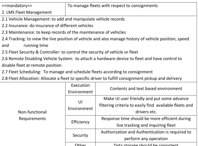
In order to clearly represent the non-functional and functional requirements a business service is used as in below Table 2. It depicts the functional and non-functional requirements with a brief detail. The business service scenario is designed by using refined feature diagram and refined use-case model diagram.
To determine the effects of business service and features BSCV decision model for the BS (Business Service) and UCM (use-case model) constructed on this refined UCM and BSS (Business service scenario) are used. As depicted in Table 3 and Table 4.
(DOI: dx.doi.org/14.9831/1444-8939.2014/2-4/MAGNT.28) Table 2 Business Service Scenario
<<mandatory>>
2. LMS Fleet Management
To manage fleets with respect to consignments 2.1 Vehicle Management: to add and manipulate vehicle records
2.2 Insurance: do insurance of different vehicles
2.3 Maintenance: to keep records of the maintenance of vehicles
2.4 Tracking: to view the live position of vehicle and also manage history of vehicle position, speed and running time
2.5 Fleet Security & Controller: to control the security of vehicle or fleet
2.6 Remote Disabling Vehicle System: to attach a hardware device to fleet and have control to disable fleet at remote position
2.7 Fleet Scheduling: To manage and schedule fleets according to consignment
2.8 Fleet Allocation: Allocate a fleet to specific driver to fulfill consignment pickup and delivery
Non-functional Requirements
Execution
Environment Contents and text based environment UI
Environment
Make UI user friendly and put some advance filtering criteria to easily find available fleets and
drivers etc.
Efficiency Response time should be more efficient during live tracking and inquiring fleet
Security Authorization and Authentication is required to perform any operation
Other Data storage should be consistent
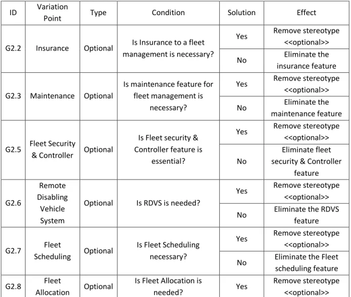
By using Table 2 and business scenario G2 in Table 3 is extracted. And showed in Fig.10 variations points can be selected or not selected by using BSCV model for UCM. The important element in software development is
SPLA which is also used as core asset as we have described in previous section that SPLA has three main view types e.g. (C&C, module) can be used in this case study.
Table 3 BSCV decision model for business service of LMS
ID Variation
Point Type Condition Solution Effect
G2
LMS Fleet Management
Optional
Does a Fleet Manager or QA Inspector need LMS
Fleet management?
Yes Eliminate stereotype <<optional>> No
Eliminate ‘LMS Fleet management’ business service
The runtime presence of elements and interaction between the elements is defined by
C&C view. While in C&C view components are units of the system’s which interact with
(DOI: dx.doi.org/14.9831/1444-8939.2014/2-4/MAGNT.28) each other using various different ways like
complex communication protocols and RPC
etc.
Table 4 Decision model BSCV for use case model of LMS
Conclusion
The purposed[13] study on managing variability in SPL gives good artifacts and processes to manage variability at different phases of software product development. Software products can be developed so easily and rapidly if we have an architecture that can
accommodate future changes easily. The problem that we face during SPL development is variability that is the core issue in the development of SPL. There are many models that are purposed to cater this issue but failed to give some standard solution. For somehow ID Variation
Point Type Condition Solution Effect
G2.2 Insurance Optional Is Insurance to a fleet management is necessary?
Yes Remove stereotype <<optional>>
No Eliminate the
insurance feature
G2.3 Maintenance Optional
Is maintenance feature for fleet management is
necessary?
Yes Remove stereotype <<optional>>
No Eliminate the
maintenance feature
G2.5 Fleet Security
& Controller Optional
Is Fleet security & Controller feature is
essential?
Yes Remove stereotype <<optional>> No
Eliminate fleet security & Controller
feature G2.6 Remote Disabling Vehicle System Optional Is RDVS is needed?
Yes Remove stereotype <<optional>> No Eliminate the RDVS feature G2.7 Fleet Scheduling Optional Is Fleet Scheduling necessary?
Yes Remove stereotype <<optional>> No Eliminate the Fleet
scheduling feature G2.8 Fleet Allocation Optional Is Fleet Allocation is needed? Yes Remove stereotype <<optional>>
(DOI: dx.doi.org/14.9831/1444-8939.2014/2-4/MAGNT.28) comparatively the purposed processes and
artifacts gives better solution including entertaining some problems of existing models like Cobra, PuLse etc. Now in this paper we have focused on implementing a real case study on purposed models, process and artifacts to see how to manage and identify variability throughout the life cycle of SPL. Many issues are resolved that are purposed in upper section of this paper in step 1 introduction. However we face some implications during the implementation of our case study. By using this purposed processes and artifacts domain model becomes too mess that causes some serious issues at application level.
We have divided issues into two categories that occurs during the implementation of our case study LMS first category is general issues and second is specific to domain engineering
issues. In general issues purposed model gives us first class representation of variant points and also describes the dependences between the architectural elements however this models does not define a standard solution to some specific issues of domain engineering like over generalization and over trivialization in which during the analysis of a new domain there are two main issues that are raised very frequently. First, the analyst does know about the exact requirement of variability during product line so this leads towards over generalizing. Second is the complexity of understanding domain detail and the particularly to domain variability is not sufficiently understood this is called over-trivialized. Similarly other issues like over simplification, mechanism impact and resource impact etc. are some issue relevant to domain engineering that needs to be addressed by standard way.
References
1. Bosch, J. Architecture-centric software engineering. in Proceedings of the 24th International Conference on Software Engineering. 2002. ACM. 2. Clements, P. and L. Northrop, Software product lines: practices and patterns. 2002.
3. Pohl, K. and G. Böckle, van~ der Linden, FJ, Software Product Line Engineering: Foundations, Principles and Techniques. 2005, Springer-Verlag New York, Inc., Secaucus, NJ, USA.
4. Linden, F., van der, SCHMIDT, K. and ROMMES, E.,(2007): Software Product Lines in Action: The Best Industrial Practice in Product Line Engineering, Springer-Verlag New York, Inc. Secaucus.
5. Loesch, F. and E. Ploedereder. Optimization of variability in software product lines. in Software Product Line Conference, 2007. SPLC 2007. 11th International. 2007. IEEE.
6. Kim, Y.-G., et al. Managing variability for software product-line. in Software Engineering Research, Management and Applications, 2006. Fourth International Conference on. 2006. IEEE.
7. Razavian, M. and R. Khosravi. Modeling variability in the component and connector view of architecture using UML. in Computer Systems and Applications, 2008. AICCSA 2008. IEEE/ACS International Conference on. 2008. IEEE.
8. Bachmann, F., et al., A meta-model for representing variability in product family development, in Software Product-Family Engineering2004, Springer. p. 66-80.
9. Becker, M. Mapping variabilities onto product family assets. in Proceedings of the International Colloquium of the Sonderforschungsbereich. 2003. 10. Sinnema, M., et al., Covamof: A
framework for modeling variability in software product families, in Software
(DOI: dx.doi.org/14.9831/1444-8939.2014/2-4/MAGNT.28) Product Lines2004, Springer. p.
197-213.
11. Gawley, R. Automating the identification of variability realisation techniques from feature models. in Proceedings of the twenty-second IEEE/ACM international conference on Automated software engineering. 2007. ACM.
12. Sinnema, M. and S. Deelstra, Classifying variability modeling techniques. Information and Software Technology, 2007. 49(7): p. 717-739. 13. Kim, Y.-G., S.K. Lee, and S.-B. Jang,
VARIABILITY MANAGEMENT FOR SOFTWARE PRODUCT-LINE ARCHITECTURE DEVELOPMENT. International Journal of Software Engineering and Knowledge Engineering, 2011. 21(07): p. 931-956.
14. Bayer, J., et al. PuLSE: a methodology to develop software product lines. in Proceedings of the 1999 symposium on Software reusability. 1999. ACM. 15. Atkinson, C., J. Bayer, and D. Muthig,
Component-based product line development: the KobrA approach, in Software Product Lines2000, Springer. p. 289-309.
16. Harsu, M., FAST product-line architecture process2002: Tampere University of Technology.
17. Ardis, M., et al., Software product lines: a case study. Software-Practice and Experience, 2000. 30(7): p. 825-47.
18. Bergey, J., et al., Basic concepts of product line practice for the DoD, 2000, DTIC Document.
19. Bachmann, F. and P.C. Clements, Variability in software product lines, 2005, DTIC Document.
20. Berg, K., J. Bishop, and D. Muthig. Tracing software product line variability: from problem to solution space. in Proceedings of the 2005 annual research conference of the South African institute of computer scientists and information technologists on IT research in developing countries. 2005. South African Institute for Computer Scientists and Information Technologists.
21. Bosch, J. Software variability management. in Proceedings of the 26th international Conference on Software Engineering. 2004. IEEE Computer Society.
22. Lee, K., K.C. Kang, and J. Lee, Concepts and guidelines of feature modeling for product line software engineering, in Software Reuse: Methods, Techniques, and Tools2002, Springer. p. 62-77.
23. Roubtsov, S. and E. Roubtsova. Modeling evolution and variability of software product lines using interface suites. in Workshop on Software Variability Management. Editors Jilles van Gurp and Jan Bosch. Groningen, The Netherlands. http://www. cs. rug. nl/Research/SE/svm/proceedingsSVM 2003Groningen. pdf. 2003.
24. Thiel, S. and A. Hein, Systematic integration of variability into product line architecture design, in Software Product Lines2002, Springer. p. 130-153.
25. Belategi, L., G. Sagardui, and L. Etxeberria. Variability management in embedded product line analysis. in Advances in System Testing and Validation Lifecycle (VALID), 2010 Second International Conference on.
![Figure 3 Features and Product are displayed using enhanced product map (EPM) [13]](https://thumb-us.123doks.com/thumbv2/123dok_us/1419210.2689959/6.893.111.808.217.599/figure-features-product-displayed-using-enhanced-product-epm.webp)
![Figure 4 Refined use-case model [13]](https://thumb-us.123doks.com/thumbv2/123dok_us/1419210.2689959/7.893.114.812.152.961/figure-refined-use-case-model.webp)